The Case of the Dead Mini5SX
Tags: computer nec cpm mini5 bungo dumping pickups repair power-supply word-processor capacitors retrochallenge retrochallenge-october-2022
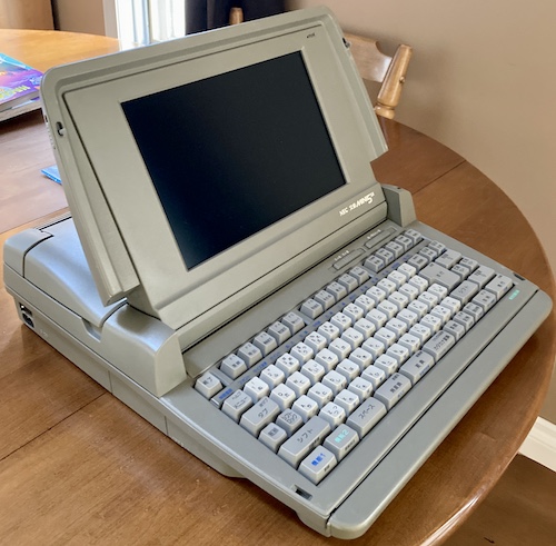
In order to get a copy of Tetris for the NEC mini5 series of word processors, I had to buy it along with a whole word processor set from the previous owner. This LCD-based mini5SX is sleek, attractive, surprisingly heavy, and broken. Very, very broken. Let’s see if we can fix up this grey beast, and dump its ROMs.
This machine offers many fewer ports than the mini5HA, which is to be expected with its more compact nature.
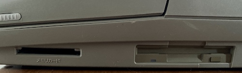
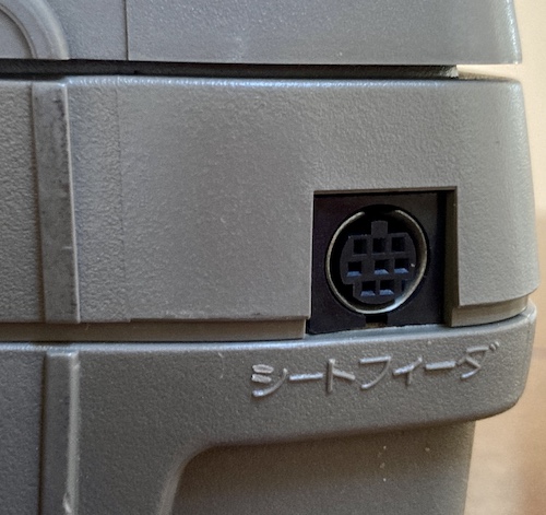
Only a memory card slot and a sheet feeder1 port are offered. I would really have liked a serial port here instead, NEC!
There is also a cover on the underside, held on by one of those screws that can be undone with a 100-yen coin. It contains a 40-pin connector and is marked “expansion slot.” My bet is that this is meant for a modem.
Although I didn’t take any pictures, there is also a slide-out carrying handle in front of the keyboard so you can easily take your Bungo on the go-go. That handle seems pretty sturdy, although it’s only tied into the top half of the case.
Unlike some other computers in the hoard, the mini5SX was bought on Mercari, where it was being sold by the owner and not some nth-generation reseller or junkyard. This person was nice enough to explain the fault in the ad. Their word processor used to work, and they’d test it once in awhile, but the last time they took their beloved companion out (to play Tetris of course,) it wouldn’t start up. There would be a dim flicker of the power light, it would extinguish, and then no response. Thus, the sale.
In total, it came with the following, about twelve kilos of stuff:
- The mini5SX itself, broken;
- Six original manuals, all about half an inch thick;
- A figure-eight power cord;
- A VHS tape about how to use the mini5 (to be dumped;)
- A box of original floppy disks;
- Tetris, in its slip case with manual
Not knowing much about the mini5’s internal structure, I decided to start by opening it up and finding the power supply. I hoped that I would find something incredibly obvious to replace, like a vented capacitor.
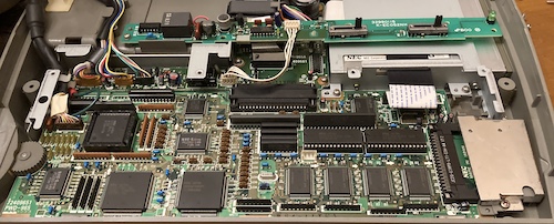
Crack It Open
A bunch of Phillips screws hold the machine together from the bottom, and then – like on the PC-9801 laptops – you have to pry up some plastic clips. Once the “top part” is separated, you set it on the side so you don’t tear the video cable. This exposes the keyboard, which has a bunch of obvious screws to remove it, and the printer, which also has many obvious screws.
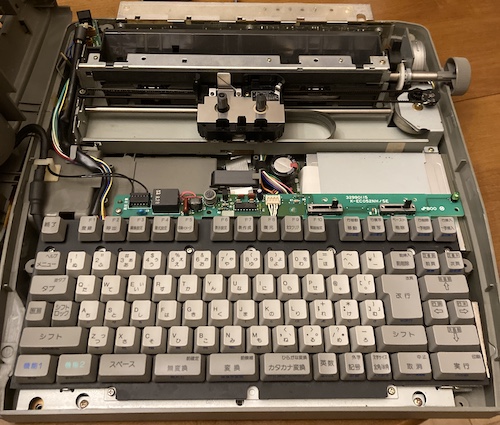
Once the keyboard is removed, you can get right at the motherboard. Look, here’s the 23c4001 mask ROMs that likely contain the BIOS, CP/M, and maybe a few other surprises. They have a date code starting with 91. We’ll be dumping these in a bit. Thanks for socketing these, NEC!
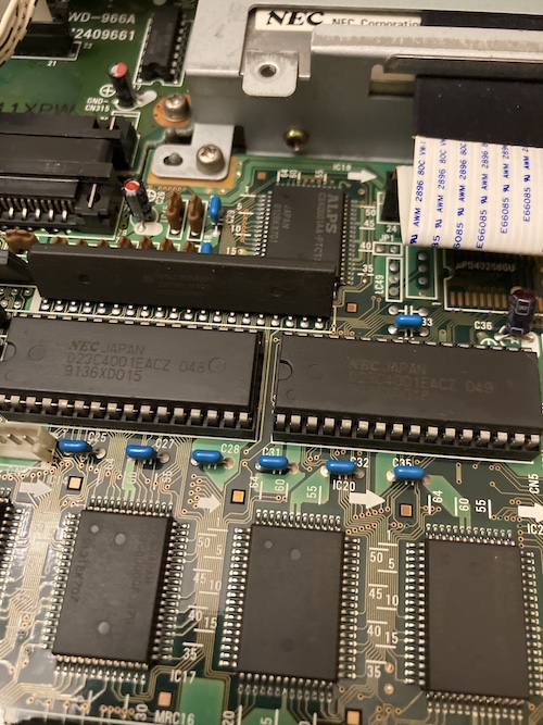
Note that the floppy drive is an NEC-branded unit and connected with a flex cable. This is very similar to the PC-9801NS/T.
Lots of custom chips; big gate arrays and specialized mask-ROM microprocessors to keep the board small and the BOM cost down. I hoped that none of these had gone bad.
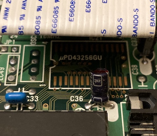
Under the floppy cable is this interesting surface-mount footprint to install a missing µPD43256 SRAM, along with an unpopulated footprint for a four-pin connector.
The backup battery is hidden under the printer, waiting to strike. It is a truly massive 4.8V 250mAh nicad.
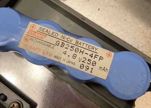
Most likely, it needs this voltage and capacity because it’s keeping some RAM chip alive for awhile – remember that the mini5HA was complaining about power loss and system reset on startup.
As you would expect, I noticed that the backup battery had indeed began to leak, creeping up the negative terminal of the connector into the power supply. Why does the power supply handle the clock battery? Beats me, but at least it didn’t leak on the motherboard.
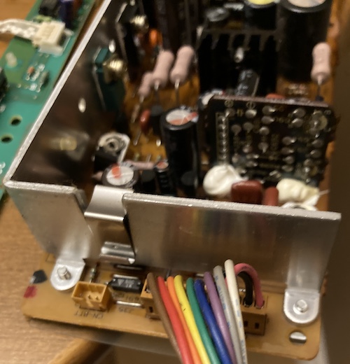
That battery goes into the three-pin connector on the left (the middle pin is unused.) The power supply connects to the rest of the system with this 11-conductor rainbow cable. Each is a different colour, which tells me that we’re dealing with at least 10 different voltage rails plus ground. Probably not an easy swap with a PicoPSU, huh?
Here’s where I found out what the problem was.
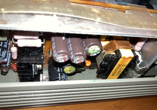
A lot of bright green goop is all over the power supply PCB. The solder-side of the board, which faces the battery, looks fine. I suspect that this was either capacitor leakage or somehow the battery electrolyte leaking onto this through gravity, as the machine is meant to be stored on its end, with these caps facing toward the floor.
Some deft screwdriver work later, and the power supply board was out. It took a trip to the sink, where I tried my best to get all of the goop off. Let’s take a look and see if this power supply board is even salvageable.
Power Surprise
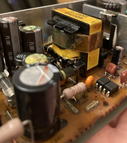
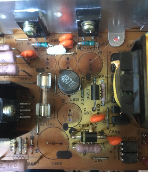
The leakage, whatever it is, has done a number on the power supply board. There are diodes, resistors, and jumpers with corroded legs. Incredibly, the PCB itself is bleached where the goop has crept:
Desoldering these caps was a non-stop episode of fish stink. I started out testing each one with an ESR meter, and didn’t find a single one that actually passed. One 1000µF cap with a particularly leaky butt had 100Ω of ESR – it’s supposed to be 0.1Ω!
The worst offenders for leakage appeared to be the brown Nichicon PL(M) series. I am not sure why these failed so dramatically in this machine, but with this level of damage, I will definitely be looking out for them from now on in everything else from the early 90s.
Some passives also had greened-up legs. I desoldered them, cleaned the legs with my grinding pen (easier said than done – holding them still is the hardest part,) tested them, and then tinned the legs to protect against further corrosion. Everything seemed fine, which is a nice outcome.
Here is the (long) cap list for this power supply. I don’t think anyone else in human history is going to ever recap another one of these, but if you do, leave a comment. We can start a little club, and make t-shirts:
| Position | Capacitance (µF) | Voltage (V) | Remarks |
|---|---|---|---|
| C609 | 10µF | 50V | |
| C613 | 1µF | 50V | |
| C614 | 47µF | 50V | |
| C651 | 1000µF | 25V | Tall/narrow |
| C652 | 1000µF | 25V | Tall/narrow |
| C654 | 2200µF | 10V | |
| C655 | 1000µF | 10V | |
| C657 | 4.7µF | 50V | |
| C658 | 1000µF | 25V | |
| C659 | 100µF | 25V | |
| C660 | 220µF | 100V | Unusually high voltage |
| C661 | 220µF | 50V | |
| C662 | 47µF | 50V | |
| C663 | 1000µF | 16V | |
| C664 | 22µF | 50V | |
| C691 | 33µF | 16V | On “sub-board” |
Surprisingly, I had most of these caps on hand already (some are extras, ordered during the process of repairing other NEC products.) A bunch of them are fairly high voltage (50V) with C660 being super weird. 100V feels like a lot for a 220µF cap!
Before I reintroduced the PSU to the machine, I checked the motherboard for obvious shorts. I read 68Ω between 5V and GND, which is nowhere near a short.
Recapping the supply cost me a few evenings, and a wait for Mouser to deliver the three values of caps that I didn’t have on hand. Some pads were ugly and didn’t want to accept new solder until they had been partially tinned, braided, and then re-tinned again. As usual for power supplies, I had much more trouble trying to keep the leftover thermal paste on the switching transistors from sticking to everything.
Dump and Bump
Before putting the machine back together, I decided to extract the system’s ROMs and dump them. At least if the re-capped power supply went haywire and burned up the motherboard, the ROMs would be safe.
There’s one big problem with the ROMs: my TL866 EPROM programmer doesn’t list the 23c4001 mask ROM as being usable with the software. This might be because the chip-selects on the 23c4001 are user-configurable. Let me explain by showing you a picture from the datasheet. Please pay special attention to pins 1, 22, and 24.
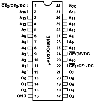
That’s right: the chip enables and output enables can be active-low, active-high, or “don’t care.” It’s up to whoever designs the masked ROM to decide which. Having two different chip enables (which seem to be OR’d together) probably simplifies decoding in some way that I’m not seeing at the moment.
This isn’t unique to the 23c4001: I’ve run into this problem before with the 23c256 as well. That’s my guess as to why the TL866 software doesn’t support these chips; they don’t know how a random 23c4001 has been configured. And neither did I.
When I tried the naïve approach of telling it I was loading an NEC 27C4001, the chip responded with an ID of $FFFF – which told me I wasn’t reading from the chip properly, and it was just giving me back an empty bus. The same was true, unfortunately, for 27c040 pinouts.
I went back and checked the motherboard to figure out how the enables worked. Pin 1, the second /CE input, was connected directly to +5V (2Ω resistance,) so it is likely set to “active low,” or at least “don’t care,” and unused by the system. On the TL866, during reading the chip ID, the pin appeared to rise to something close to +5V. Logically, I didn’t see any reason to believe OE and CE were not active-low on an x86-adjacent system. My guess is that this functionality exists to save a NOT-gate, or to confound reverse engineers for a couple more seconds until they put a scope on it, but NEC didn’t use it on this machine. That means this 23c4001 should read like any other one-CS, one-OE EPROM, and we just needed to figure out if those two inputs were active-low or active-high.
After debating whether I should build an adapter, I finally just decided to go for it, ignore the ID check, and read out the ROM as a 27C4001. It’s not like I could hurt this thing by pulling an active-low signal high, or the opposite. They’re designed for those levels during normal use! So I ran this:
% minipro -p M27C4001@DIP32 -r upd23c4001eacz-048.ic16 -y
[..]
WARNING: Chip ID mismatch: expected 0x2041, got 0xFFFF (unknown)
Reading Code...  4.50Sec  OK
Success! Actual data was read out of the chip - not just a stream of $ff . Do mask ROMs not have chip ID bits? A closer reading of the datasheet didn’t answer that question either way.
Using the same technique, I dumped the other ROM as well, and ended up with two lumps of binary data that occasionally had “string-like” chunks inside them when viewed in a hex editor. Of course, they were nonsense… why is that?
Scroll back up to the pinout again. I’ll wait. Yep, the 23c4001 only has 8-bit output on its data pins (“O” in the pinout.) So how can it fill 16-bits of instructions for the 16-bit NEC V20?
That’s why they (and many other systems) have two ROMs: one fills up the lower 8 bits, and the other fills up the higher 8 bits of a 16-bit word. So I had to write a quick little script to stitch them together in order to take a better, more human-readable, look at the data.
Once I had done so, I checked the output for strings again and found this little gem:
Hirosima Toyo Carp Naka World in Hirosima city.Programed by Yoshikatsu Gouda 1991.1.12 and First coding 1989. 9.15 Friday for VX952 Last coding 1990.12.25 Tuesday for VX958 Special thanks to Hitomi
Good taste. I also cheer for the Hiroshima Carp.
There’s lots of other references in here for things like paths to dictionaries, fonts, default filenames, etc. There’s also the CP/M 2.2 sign-on header, as expected.
I’m going to see what is involved in getting these ROMs into MAME, so that we can begin developing emulation support (and preservation) of the system. In the meantime, I have uploaded the mini5SX ROMs to the Internet Archive, and I heartily encourage you to download your own copy and hoard it for all eternity.
Wapuro, Test Thyself
Oh yeah, with all this excitement around ROMs and caps, I forgot that I had to actually test the machine.
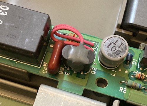
The PCB that contains the contrast slider above the keyboard has two transistors glued together, with two wires coming out of the potting compound. Very strange.
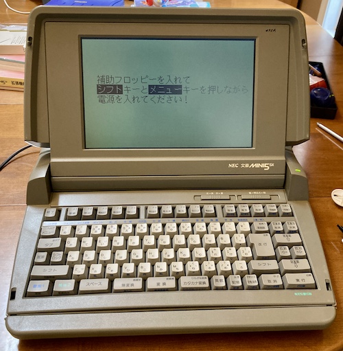
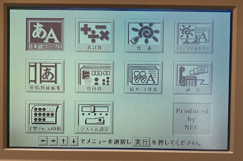
I put it all back together, plugged it in, switched it on, and after fiddling with the contrast dial, something showed up on the screen.
It took a few seconds more for the backlight to appear – most likely bad caps in the monitor section, like on my PC-9801NS/T, which I’m not in any mood to fix right now – but it works. I had a working mini5SX!
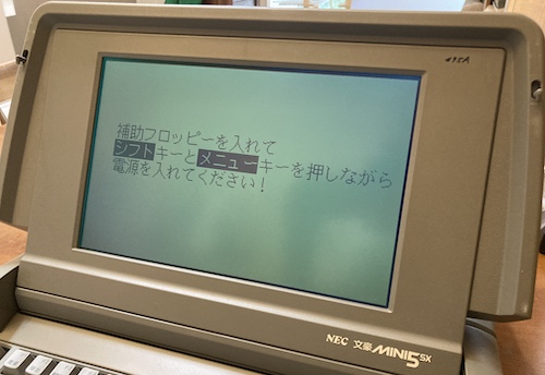
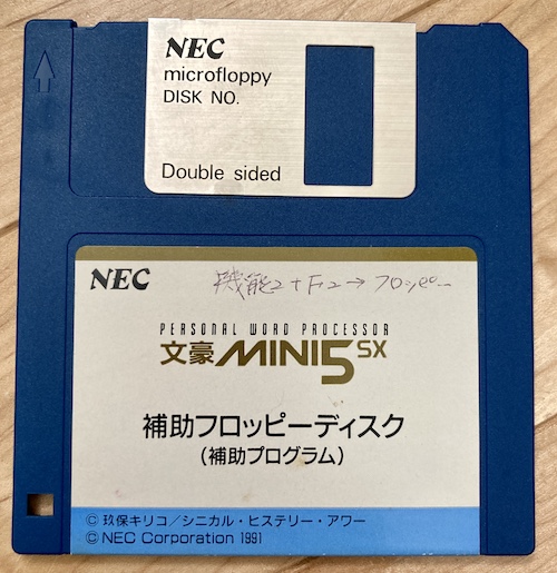
Of course, the error screen was something new. It was complaining about wanting me to insert the “auxiliary disk” and hold SHIFT + MENU while restarting the machine. I fished through the disk box until I found one marked “auxiliary,” and did as the computer demanded.
I’m not sure what the handwritten label in the corner is all about. It says “Function 2 + F2 = Floppy.” Maybe it’s a shortcut to get to floppy formatting/file management tools. I’ll test that later.
After switching the keyboard into English input mode, I was now able to write out a couple of quick test sentences:
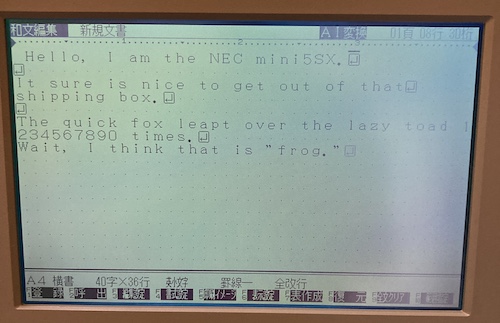
The left-aligned mini space bar still annoys me quite a bit, just like it did on the mini5HA, so I’m not going to be writing any manifestos on this thing anytime soon. The return key also seems to have a little bit of wear, and has to be struck fairly hard to work. This will probably clean itself up in time.
I will dump all of these floppies soon, so that I’m not worried about eating up one of them. If the “auxiliary” disk is needed to recover a system after it has lost its batteries, then lots of other people will need it too. Most sellers don’t include the disks.
The previous owner left the write-protect tab set to “off” on every single disk, so obviously they liked to live dangerously.
Conclusion
Although I bought this machine only to get Tetris, I couldn’t bear to see it in such poor condition. Now I have two Bungos, which I think we can all agree is what makes a house a home.

Repair Summary
| Fault | Remedy | Caveats |
|---|---|---|
| Does not power on. | Replace badly leaked capacitors and clean up corrosion to power supply PCB. | |
| Battery corrosion. | Remove backup battery. | The missing battery may make the machine less usable, having to insert the “auxiliary disk” on cold startup. Maybe a FRAM mod? |
-
This is probably the same thing as the hagaki feeder, though maybe the sheet feeder works differently. ↩