MZasters of the Universe
Tags: computer sharp mz700 capacitors power-supply repair
This poor Japanese Z80 computer is literally screaming out for someone to come and fix it. With the some troubleshooting and a little luck, I got it back on the open seas and pumping out its fantastic chunky colour graphics once again.
Sharp made a ton of computers, not just the X1turbo and X68000. Before those popular PCs, they had their most notable successes with the MZ line. One of the most beloved machines from that series was the MZ-700.
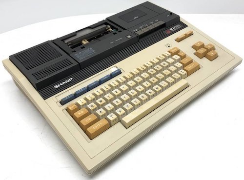
This computer, the one that I bought from auctions, is an MZ-731, which is one of the most fully-equipped versions of the MZ-700 that you could buy. It has a built-in tape deck and pen plotter. Like the X1, there is no BASIC in ROM, so you need a tape cassette or other software to easily do things with the computer.
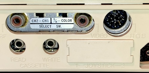
There are a lot of options for video output, making this machine very flexible: composite video, RF, a DIN8 digital-RGB output. There’s also two jacks for reading and writing tape cassettes, and a blocked-off section for a joystick port that I don’t have.
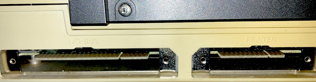
The expansion I/O port and the printer I/O port are both blocked off by plates on my unit, seemingly never used, but a quick removal of the screws exposes them. We’ll come back to this expansion I/O connector in a future entry.
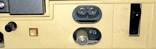
Finally, the more boring end of the case has a reset button, a volume knob, and the power plug. You also get the requisite Japanese “FG” frame-ground connector, and a giant rocker switch for power.
Help Me, Dr. MZ!
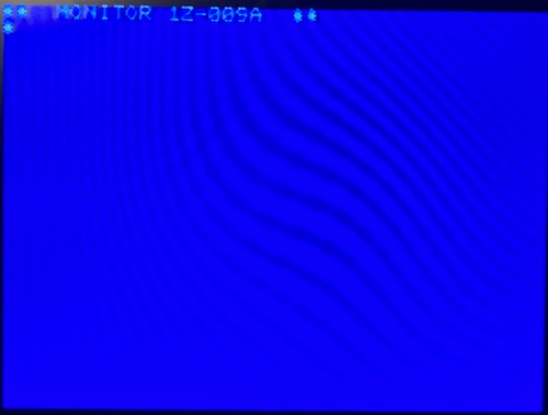
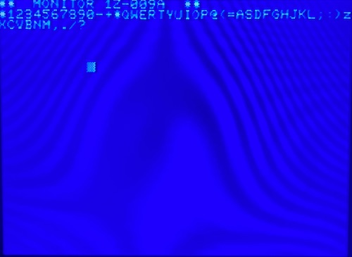
What’s wrong with this unit? Besides a missing plotter cover, it has something crazy going on at startup:
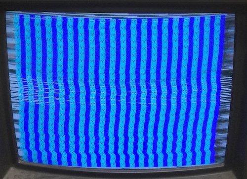
This looks like bad, wobbly sync – and something going on with the video RAM. My first guess was a bad power supply.
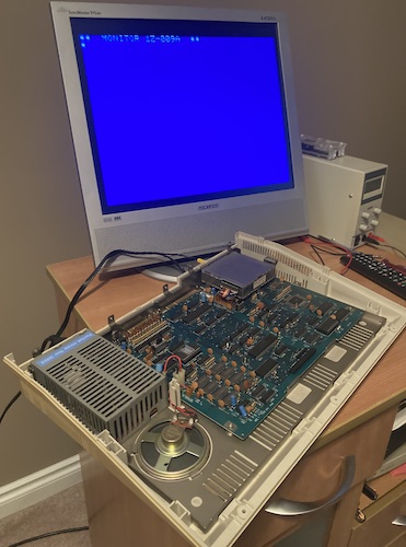
When it arrived, I plugged it in and turned it on. This time, I had a screen full of random characters, but relatively solid sync (it’s worth mentioning that I was using an LCD to view it at the time – my long-suffering Samsung 910MP.)
What I also had was an ear-piercing oscillating shriek coming from the general vicinity of the power supply. I shut it off immediately and started dismantling the computer.
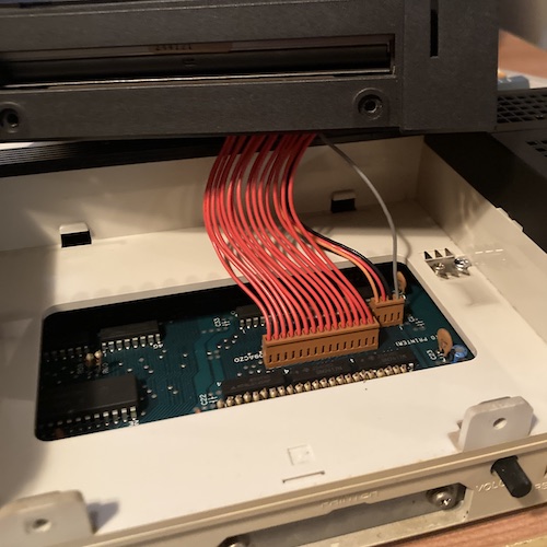
Removing the cassette and plotter modules are fairly easy: there’s some fine-thread screws on the back and then you pull the whole thing up and out. Unplugging the cables is easy after that. There are some mysterious switches underneath for “PRINTER” and “RECODER” (sic) which I assumed tell the computer whether or not the peripheral is attached1.
I unplugged these modules and tried to power up the computer again, thinking that maybe one of them is shorted or otherwise seized and drawing too much power. No obvious difference was noticed.
After removing some more screws under the keyboard, and working my fingertips around the periphery of the back case, the top popped right off, exposing the motherboard.
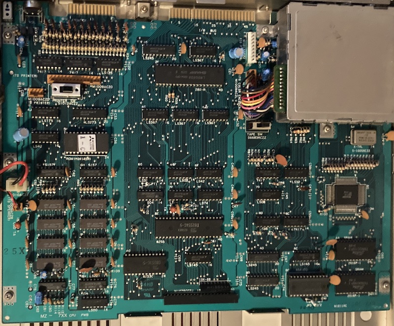
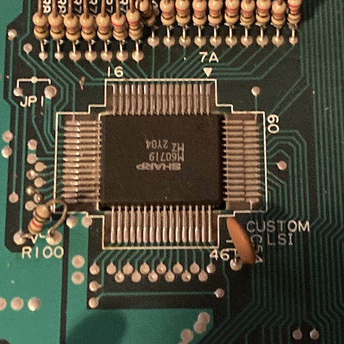
Sharp is very proud of the one custom chip in this system: they call it out on the silkscreen as “CUSTOM LSI2.”
Nothing seemed to be especially bad. It was here that I noticed that the extremely compact power supply box – slightly larger than an original iPod – only produced ground and “VCC,” which I assumed to be five volts based on the lack of other voltage regulation on the motherboard.
The Tension Is Getting Good
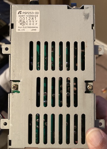
The power supply, a Fuji Electrochemical PSP253-00 with a Sharp part number DUNT-1309ACZZ, came out with five more screws. Note that this is threaded directly into case plastic, so be gentle.
With the power supply removed, I decided to check quickly for motherboard shorts. Between the “VCC” and “GND” power inputs, I noticed 46Ω of resistance on my cheap meter. No shorts, which also made some sense as the computer did come up and display something.
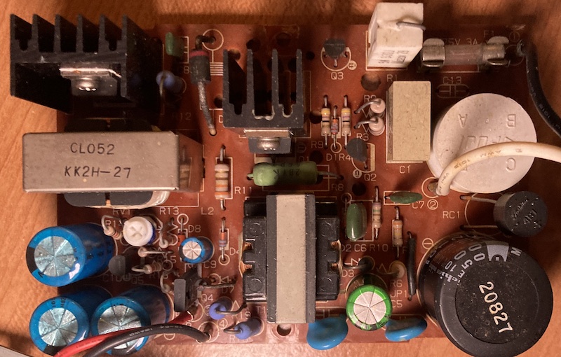
I took the power supply apart. As I suspected from its small size, it is a switch-mode power supply, with a very compact size. Despite the challenges involved, Sharp appears to have done a good job keeping the aluminum electrolytic capacitors spaced far away from heat-generating elements like the switching transistors. Everything is 105°C rated as well.
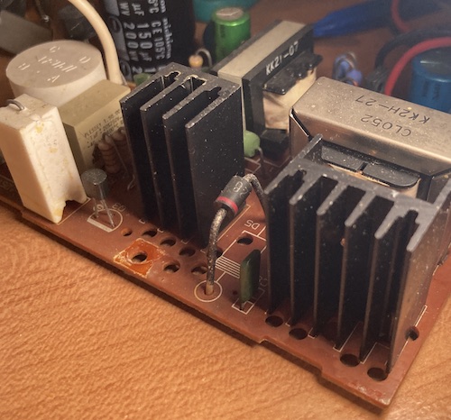
The heatsinks also have these mysterious holes drilled in the board near them. My guess is that this is for alternative footprints of heatsinks, in case the primary supply-er (get it?) couldn’t make it happen. They may also provide some minor additional cooling?
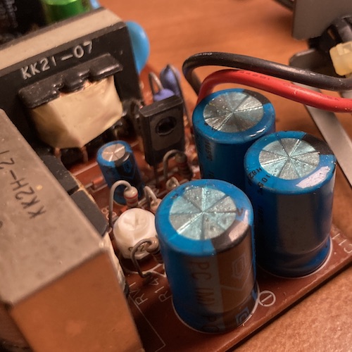
It was here that I noticed this strange blue covering on top of several 1000µF caps near the edge of the board. My best guess at this time is that it was some kind of conformal coating, although the other caps didn’t have it. I thought that was very strange, considering the gas vents on an aluminum electrolytic capacitor really shouldn’t be clogged like that, ever. What’s more, it seemed to have bubbles and flecks of other material inside.
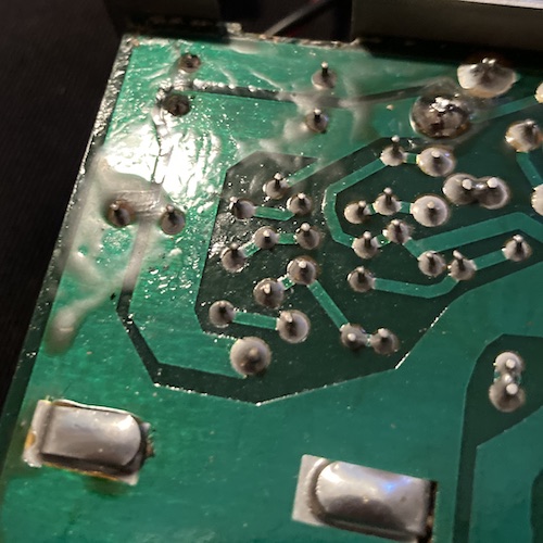
I also noticed some intermittent chalky white goop on the bottom of the board. I’m still not sure what this is: it’s clearly not old flux. Maybe it is conformal coating that was applied very poorly?
I cleaned it off, and it didn’t smell like anything distinctive, but it made the q-tip jet black almost immediately. After that, I took an in-circuit ESR test of the suspicious 1000µF capacitors, which all came back with complaints or crazy values.
I pulled the caps out and measured them out of circuit, where they measured with semi-high ESR but relatively sane capacitance values. Replacement-worthy, sure, but not likely to be the cause of all the shrieking.
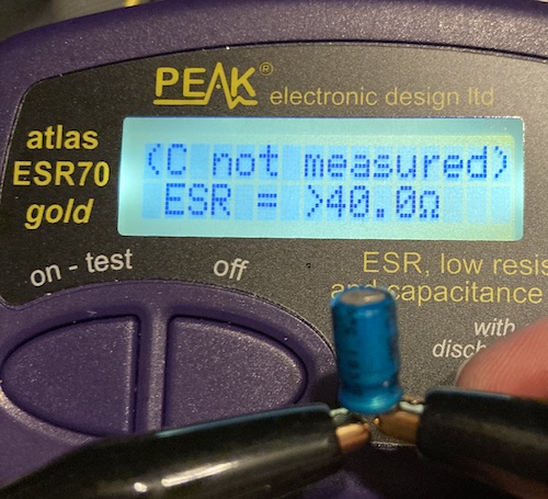
I then repeated the ESR test on the other two caps, and found that the teeny-tiny 33µF/35V cap acted very strangely out-of-circuit, confusing the meter so much that it was not able to measure the capacitance or ESR on it. Strangely, it did not look that bad, with no crusty cap poop left behind under it. I re-did the test a few times, and even cleaned the legs on the cap, but the ESR70 continued to condemn it.
Of course, it was late at night on a Friday, so I didn’t have a replacement for this cap on hand.
Monitoring The Situation
In the meantime, to check if the computer’s motherboard was the problem, I strapped my bench power supply up to the VCC and ground pins. I set the voltage a little low, at 4.8V, just to give me a little more breathing room in case something started to go wrong, and set the current limit at a relatively small 2A - I didn’t expect a simple Z80 system with no peripherals installed to pull more than 10W.
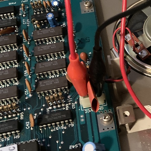
The heat shrink here is to help keep the alligator clips upright, so that they can’t slip and short to one another. Although the alligator clips have their own insulation, it’s better safe than sorry.
Once the bench power supply started flowing, the computer jumped to life and sat on a blinking-cursor screen on the built-in ROM monitor. The thing works!
Like the later X1, the MZ is a “clean computer” – no BASIC in ROM – so this is, as far as I know, all I get from autoboot. There are actually two ROMs on this system, but the second ROM is marked as being for “CG,” the character generator, which implies to me it’s the font ROM.
I didn’t have the keyboard connected, and didn’t want to fiddle with a potentially fragile keyboard cable at the moment, so I left it at that for a few days. The computer was partially reassembled and pushed to the side to make room for another patient, while I waited for my Digi-Key cart to fill up and disgorge the cap required to repair the Sharp’s original power supply.
Power, Supplied
As soon as the 33µF cap appeared, I put it into the board and reassembled the power supply. Luckily, I had not forgotten how to put the machine back together, so it quickly popped up and happily gave me a beep and the Monitor.
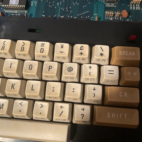
I attached the (dirty) keyboard and did a quick test: all the keys seemed to be working. One interesting feature is that you have to hit separate keys to toggle between kana input mode and English/Roman input mode. Usually that’s just one key, like Caps Lock is for capital letters.
Oddly for a Japanese machine, this computer seems to be pre-configured to tell us all about the £. Maybe that’s why the MZ series was so popular in the UK?
Load It! Internally
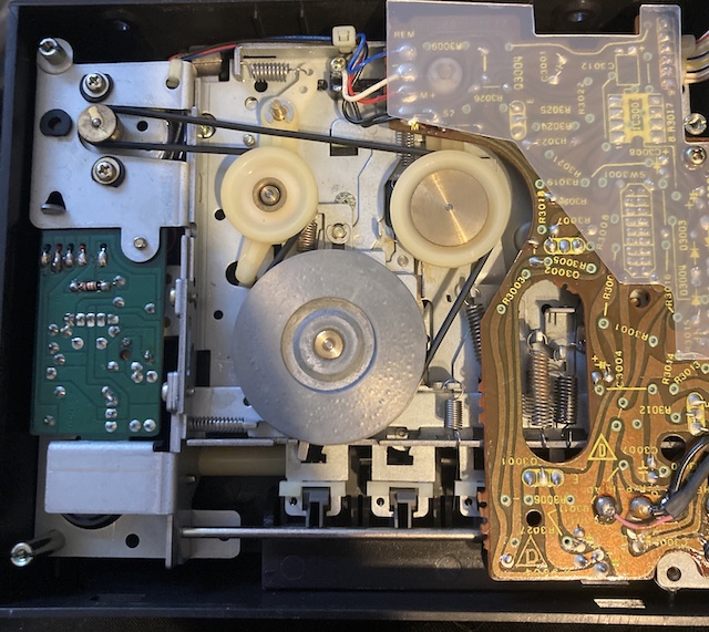
I dismantled the tape player, but found that all the belts within were in supple condition. This was a bit of a surprise, especially since the screws on the bottom holding it together were not only very tight, but still glued in from the factory.
Unfortunately, I had no MZ tapes to test with, and I couldn’t find my pile of blank tapes that I had bought a few years ago, so I went to plan B: buying one.
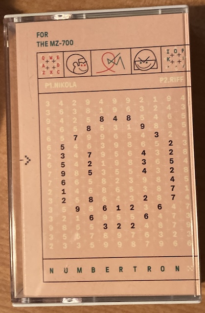
Numbertron is an independent MZ-700 puzzle game made by Joachim Froholt, and it’s published by Sharpworks. Their shipping cost was totally reasonable, and the game arrived in just under two weeks. Now I had a game to try!
When I popped the tape in, I noticed two things.
- The door didn’t really want to close with the tape in it, unless I forced the tape upwards in the lid as I was closing the lid.
- Pushing the “play” button didn’t do anything. Or the “rewind” button, or the “fast forward” button. The tape player seemed dead.
I went looking for simple culprits. The spindles seemed to turn, and I knew from the last time I took it apart that there were intact belts front and rear.
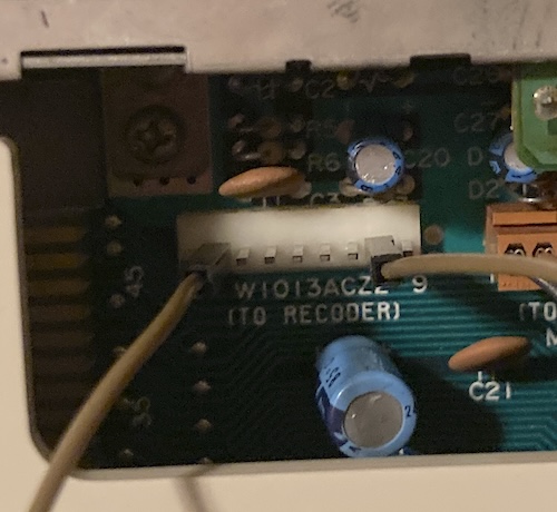
My next step was to make sure it was getting power. The MZ-700 tape drive, the DUNT-1002ACZZ, apparently has a schematic available. From that, I was able to figure out that pin 6 on the MZ-700’s connector is +5V power, with the following pins on the cassette interface’s motherboard connector looking like this:
| Pin | Signal |
|---|---|
| 4 | Remote |
| 5 | Sense |
| 6 | +5V DC |
| 7 | Write |
| 8 | Read |
| 9 | Ground (E) |
What happened to pins 1-3? We’ll get to that in a second.
You may also think it’s a little weird to have something with a big motor only receiving +5V power, but that’s the only output rail on the MZ-700’s power supply. Besides, by this point in the 80s there should have been compact, efficient, and inexpensive +5V motors available in Japan.
I checked the MZ-700 with the multimeter, and +5V was present and solid at pin 6. So I decided to start tearing apart the tape drive. After desoldering all the wires, snipping a pair of zipties, and removing the amplifier/power-supply board, I ended up being stumped about how to get the motor board out. To the internet!
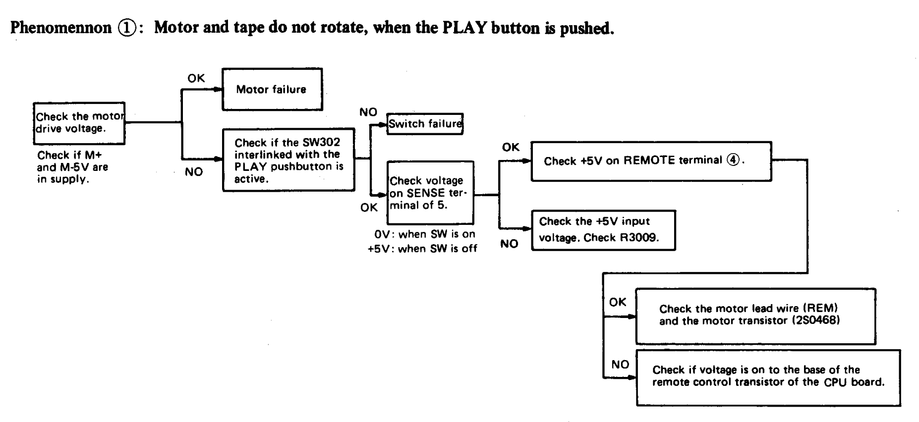
The diagnostic tree from the English MZ-700 service manual was checked. That mysterious switch from earlier should help us.
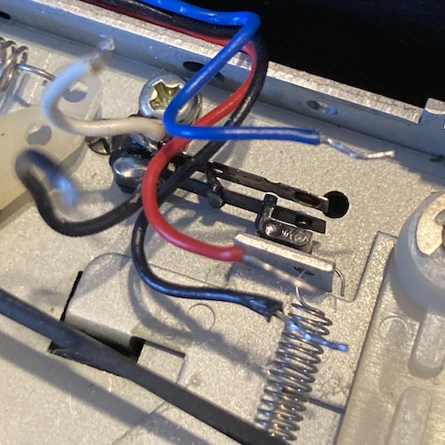
Although I couldn’t find any callouts and couldn’t get the board it is soldered into to come out, this switch is actuated by the play button. A quick check with the continuity tester showed that the black and white wires are shorted together by the pushing of the play button, so this switch is working.
SW3001, the sliding switch that toggles between record and playback when the Record piano key is pushed, also seems to change which pins are shorted as it slides. I assumed that this was fine and moved on.
I decided to head back to the motherboard, not least because Koen Martens suggested I do so. With the tape drive removed from the system, I tested pin 4 (“Remote”) before and after typing the “L” command in the bootstrap monitor. The voltage never rose off of 0.10V, which made me now suspect some part of the circuit driving the Remote pin on the motherboard.
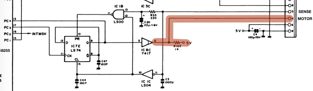
Pin 4 is fed directly from a 7417 at 8C. What is a 7417? It’s an open-collector hex buffer, the exact kind of thing you’d use to protect innocent silicon from the ravages of a motor-filled tape drive. The output is even being pulled up to +5V!
To be honest, I expected a transistor on the motherboard, because the above diagnostic tree says to look for one, but that’s clearly not how Sharp rolls. My best guess is that this diagnostic tree is outdated, not re-translated, or simply copied from the MZ-80 manual, and nobody noticed. The 7417 is something I didn’t have on hand. In fact, it seemed to be kind of annoying to find a replacement for, so hopefully it was not actually at fault.
I threw the scope onto the “REMOTE/MOTOR” output of the 7417, and I noticed that its output was stuck low. So was its input. I went back to the 74LS74 flip-flop that feeds it. That 74LS74 was getting clocked-in by the 8255, so I assumed that the 8255 (or at least most of its outputs) was in good condition.
I looked at the “SENSE” line feeding into the 74LS74, which was constantly low. At this point, I began to suspect that I might need to actually have the tape drive plugged in, and providing a “SENSE” signal, in order to accurately diagnose this circuit. So I went and plugged it in.
This time, I noticed that the “REMOTE/MOTOR” line jiggled, just a little bit, when the play button on the tape drive was pushed. I pushed stop, and then pushed that play button again. Another jiggle, but longer. I pushed stop, and then pushed that play button for a third time, and the tape drive leapt to life with a high (and holding) “REMOTE/MOTOR” line. I let it chew for a little while, to see if the drive was going to explode into a conflagration, and then decided that I should probably give it something to load.
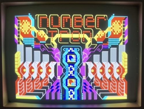
In went my brand-new retail tape of Numbertron, and I let the tape drive start its ordeal again. Within a few seconds, the Numbertron loading screen appeared, and the tape kept spinning.
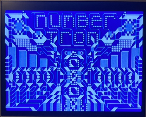
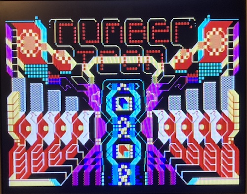
The loading screen filled itself in with colour a minute after that. Such pretty colours! It’s hard to believe this is only eight colours. Low-palette artists are hugely talented people.
A couple minutes later, at around marker 67 on the tape player’s counter, I was at the title screen.
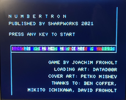
The tape drive stopped itself, as presumably the computer had dropped the “REMOTE/MOTOR” line. I was happily playing Numbertron now.
So, what was wrong with the drive? I don’t know. My best guess is that some component was rusted up, and it just needed a few cycles before it could start rolling again. When I took it apart to check the belt, everything seemed to turn freely, so I figured that the motor was in fine condition. I guess the moral of the story is “screw diagnostics, just keep pushing the button until it either works or breaks worse.”
It’s entirely possible that there’s a bad cap on the motor control board as well. I wasn’t able to figure out how to get that board out, but the schematic seems to indicate there’s a 470µF cap on there for bulk filtering the motor power supply. I would not be surprised if that’s a failed low-ESR cap. When I go back to measure the belts, I will renew my efforts to try and get that motor board out of the cassette drive.
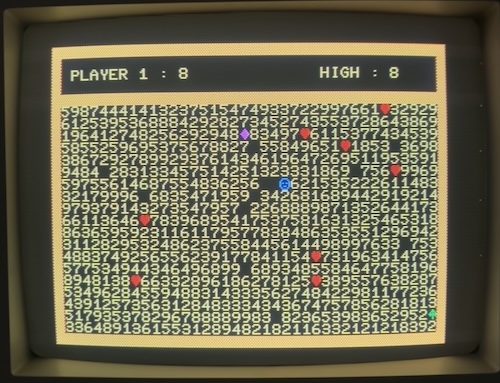
As for Numbertron? This ordeal was worth it. The game is a lot of fun, so much fun that the PC-6001 fanboy in me is a little bit jealous that it hasn’t gotten a port.
RGB
The MZ-700 has 8-colour digital RGB out. That composite output up above is kind of gross; RGB should provide a much sharper and more “computer-like” picture.
I noticed that the RGB connector on the back is an 8-pin DIN, not a 6-pin DIN like on the later Sharp X1. This made me wonder if it was a similar pinout to all the other 8-pin DIN digital RGB Japanese computers in my hoard. If so, I could use my PC-8801mkII VGA adapter or even connect it to my NEC PC-TV151 CRT monitor.
To answer my question, I found the pinouts in the MZ-700 service manual. There’s been a slight correction by someone in the past:
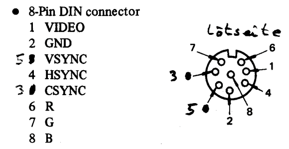
With the exception of some additional pins (CSync and composite video) the important RGBHV pins are exactly the same pinout (after modification) as the PC-8801mkII. Nice! I’m guessing that handwritten label reads “lotseite,” which would be “solder side” in German.
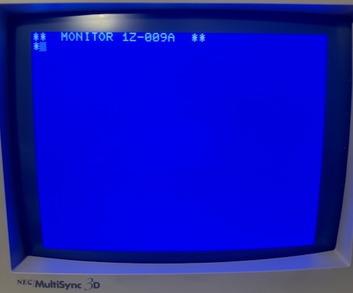
Throwing caution to the wind, I plugged it into my PC-6601mkII digital-RGB adapter and then into my freshly-recapped NEC MultiSync 3D CRT. After flipping the switch with the monitor set to “8-colour” mode, I was able to look at the Monitor. That Monitor, it looks pretty good.
I started the Numbertron tape again. Once again, I had to do the stop-play dance three times on the tape player before the motor would start to spin.
RGB is definitely the best way to experience this machine, but I’m glad that Sharp offered such a wide range of other options. Composite and RF is probably the way that most people would have experienced it when it’s new, and the outputs on those look quite good too.
Load It! Externally
The MZ-700 is nice enough to provide an external tape audio input. I used the mzf2wav tool to convert several MZT files from the somewhat incomplete MZ-700 Pack on the Internet Archive to WAV-format files that I could play from my newer computer directly into the MZ. To get it to compile on my Mac, I had to modify the Makefile to make the compiler not statically link everything.
To convert images, I had to rename the *.mzt files to *.mzf before the converter would recognize them as valid, but it did not work for some games with fancy loaders (Tiny Xevious is, sadly, one such game.) I haven’t figured out what the difference is between these two formats, other than that the MKT format seems to be able to hold more than one MZF file within a “tape.” This may require more investigation later, although I found out immediately afterward that the castool utility which ships with MAME can convert mzf, mzt, and some tape format called m12 into WAV.
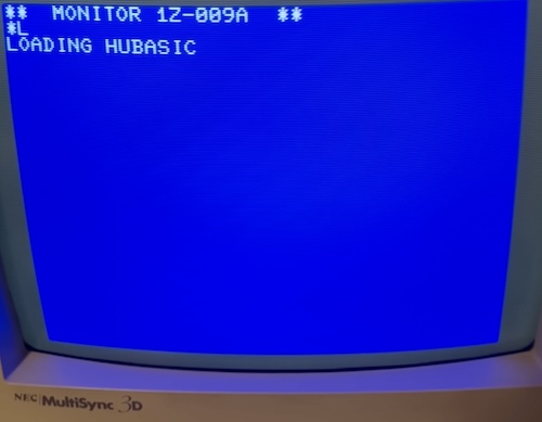
For a quick first draft, I plugged a mono male-male 3.5mm audio cable into the “Read” port of the MZ-700 and the other end into my MacBook Pro’s headphone jack, and typed L, which made the MZ-700’s monitor display PLAY. Following its lead, I then played one of the WAV files, but after over a minute the MZ didn’t seem to be picking up any header information. No “Loading…” text appeared.
Coincidentally, I ran across an Instagram post by Dutch pinball enthusiast and sci-fi author Koen Martens about getting the external tape input to work at around the same time. It turns out that you have to jump pins 1/2 (external read/write) to pins 7/8 (internal read/write.) This is a bit hacky, but it is documented in the service manual. Like Koen says in a later post, building some kind of interposer board with a switch would be a really nice way to do this.
In a later post, he also shorted the “sense” line for a reason that I wasn’t yet sure about. I decided to proceed for now without doing that, to replicate his experiment at the very least.
Thank you to Koen for writing up your findings and helping me diagnose the tape drive’s oddness!
This time, I decided to use a Hu-BASIC image, and convert it using MAME’s castool utility:
./castool convert mz ../Hu-BASIC\ v2.0a.mzt hubasic.wav
Unfortunately, this did not work to load with a mono 3.5mm cable run from my then-new MacBook Pro. I wasn’t too surprised; I had heard grumblings about the modern audio filtering “smoothing out” the hard, digital transitions that the computer expected to see.
I also tried shorting the “sense” line to “ground” as Koen did, but it also did not work. I decided to grab a slightly older computer.
Using my ThinkPad X230 running Windows 10, I was still not able to load the castool-converted WAVs on the MZ. I ended up grabbing a Windows utility, MZF2WAVGUI, which wraps the mzf2wav code in a nice if slightly eccentric interface.
After nearly an hour of experimentation, I emerged triumphant at last. On my ThinkPad, the magic recipe was:
- MZF2WAVGUI-converted image (with or without turbo load);
- Sense line shorted to ground
- About 75% volume
This was confusing to me, because you’ll recall in the previous section that I scoped the “sense” line as being low when there was no tape drive connected to the system. There is no tape drive connected now. How can it make a difference?
Doing so does make an observable difference to the computer: I noticed that with the sense line shorted to ground, the “press PLAY” indicator no longer showed up in the Monitor when I typed “L.” This is almost certainly because it is sensing that the tape player is already rolling. Otherwise, the MZ won’t start listening to the port until it thinks that it is going to receive input from the tape player.
It’s possible that there was some other signal here on the initial setup of the flip-flop that I wasn’t clever enough to catch with my scope when I was looking for basic voltages and signals earlier. Even so, it works, and a later sanity check proved that I do need to set the line low for the WAV to load, but it remains confusing. I want to go back and understand this better.
My first load was HuBASIC, which drops me into a nice but fairly bare-bones BASIC interpreter. I do have a lot of RAM to play with, one of the benefits of the “clean computer” architecture.
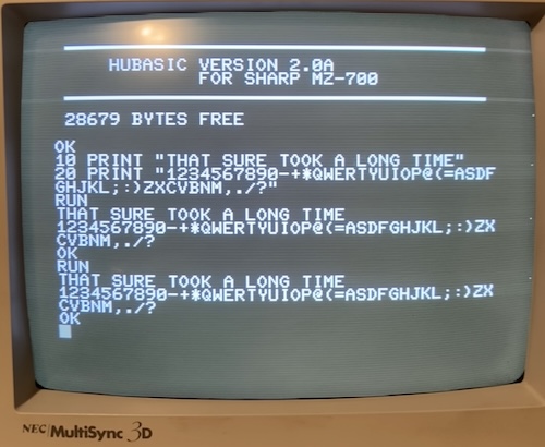
Every key on the keyboard works! I am very happy to not have to do a keyboard repair for once in my life.
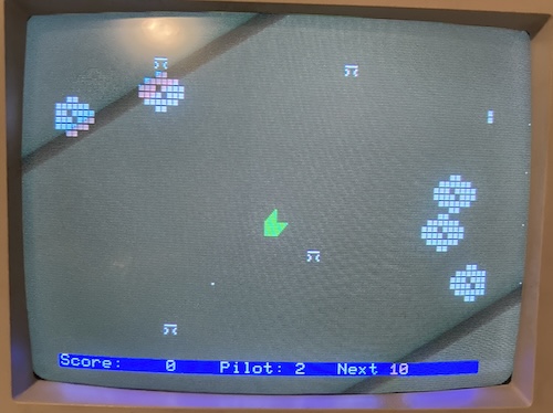
My next thing to load was Time Pilot. This is a very flashy, very quickly-animating version of the Konami classic (one of my favourite games) done entirely in tiled character graphics. I didn’t find it to be very much fun, mostly because the controls are not very responsive, but I was able to shoot down a couple of enemy biplanes.
Now I can steal games legally obtain images of software from the internet and run them on the MZ. This computer has become useful again!
I would still like to find a solution for converting these images to WAV on my Mac, and I plan on also investigating the differences between castool and the mzf2wav project in order to figure out what might have happened here. Maybe I’ll even build a tape emulator like Arduitape or TZXduino. It just won’t be today.
The Plotter Thickens
On later power cycles, I noticed that the formerly silent plotter was now making noises. It seemed like it was trying to move, which is interesting. Unfortunately, it couldn’t move very far; it seemed to be seized on its cable.
The plotter has a lot of problems in addition to this. I don’t have any pens3. The cover, and maybe other parts, are missing too. I wouldn’t be surprised if the sudden revival means that it will also need a recap. And I don’t know where to get paper for it. I also don’t actually know anything about how a plotter works, or have any software to drive it.
Because of all these challenges, I decided to leave the plotter repair for a future entry. Don’t worry, though: I’m gonna fix it. Plotters are simply too cool to leave broken, especially tiny plotters built into an adorable Japanese 8-bit.
Conclusion
Although I would hesitate to call this MZ-700 “perfectly fixed,” it’s certainly a lot better than it was when it first darkened my doorstep. I’m looking forward to exploring the entire software library of the system, and finding something to do with that expansion port.
Repair Summary
| Fault | Remedy | Caveats |
|---|---|---|
| Unstable power output and shrieking noise. | Replace 33µF aluminum electrolytic capacitor in power supply (C9) | The blue-tinged 1000µF caps were also replaced at this time, which may have also been part of the problem despite not dramatically failing. |
| Cassette drive doesn’t play. | Repeatedly try to play until it does. | There may be a faulty cap or other component on the motor board (seemingly inaccessible) which is actually causing this problem. |
| Plotter is seized. | Not fixed at this time. |
-
The “recorder” switch actually inverts the polarity of data coming off the tape. ↩
-
It looks like there is a Czech project to replicate the functionality of the MZ-1500 LSI IC (which is the same M60719 part as the MZ-700 LSI) using a CPLD and some very rigorous reverse engineering. It would be very cool to build a new-parts MZ-700 clone using this tremendous part in the future. ↩
-
Blog friend drygol seems to have adapted the cartridge from gel ballpoint pens to his plotter carriage, which looks to be the same one as used in the MZ-700. ↩