Flat Panels Aren't MultiSync 3D
Tags: computer nec video crt jc-1404hma corrosion repair capacitors homemade-hardware
While I adore my NEC PC-TV151, there is one monitor that NEC shipped to our shores that may be the ultimate CRT. This one was cheap, and this one is also very, very sick. Can I cure it so that I can enjoy CGA the way it was meant to be?
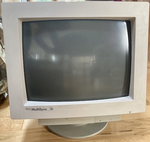
The early MultiSync series differentiated itself from the competition by being able to sync to multi-ple weirdo signals, ranging from Mac II colour to 15kHz to even EGA and CGA digital RGB. It also has a generally agreeable picture quality, and a nice industrial design, possibly because it cost a lot of money.
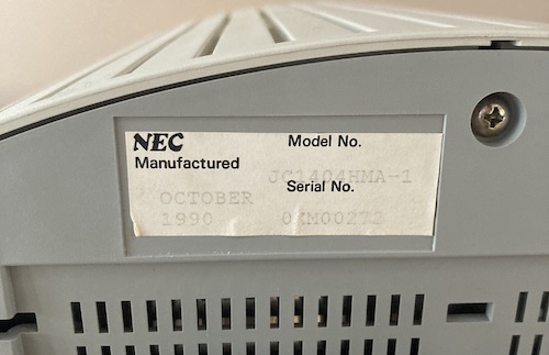
Hailing from 1990, it uses the old-school NEC logo, and some funky design elements, ranging from a sideways-rocking power switch, to all the case screws being hidden underneath.
Despite the plastics seeming fine, I heard something small and flaky rattling around inside when I moved the monitor, so something had broken at one point.
Squintin’
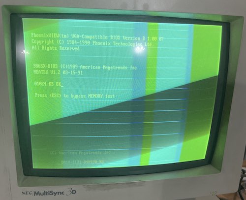
When we first got this monitor hooked up to a random PC clone in keegs’ basement, it showed a green raster with what appeared to be very bright retrace lines.
This is not a good sign, and I worried that we were dealing with a heater-to-cathode short. Allow me to explain a little bit about how a CRT works in order to show how this might have happened, using this terribly drawn cartoon and very inaccurate description.
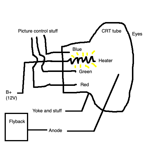
All CRTs – as far as I know – have some heater filament inside the tube. You need to heat up the guns or they don’t work. This heater sticks out quite a bit, because it heats the cathode part of the CRT, and more surface area means an easier job heating. Usually, the heater runs off the B+ voltage, which in the JB-1260M(A) I fixed earlier, is +12V DC or thereabouts.
On the neck of the CRT, the control pin for the heater is really close to the pins for red, green, and blue inputs, which in turn control the beam coming out of the respective gun (cathode) inside the tube. The guns are always firing electrons, because it takes a ton of energy to make these things work, but much less energy than it would take to start and stop them all the time. The brightness of that colour, and therefore the colour mix, is done by varying the positive voltage of the control grid sitting in front of the gun for that colour – the classic RGB colour model. More positive voltage means that the negative electron is more attracted to the control grid, and it will then be travelling at a faster speed when it hits the phosphor.
Operating a CRT involves a lot of high voltage, magnetics, and static electricity, so it’s common that things will coke up as they function. For instance, one of the big reasons CRTs go dim and wear out is because the cathodes get covered with enough gunk that you can’t fire as much juice through it anymore1.
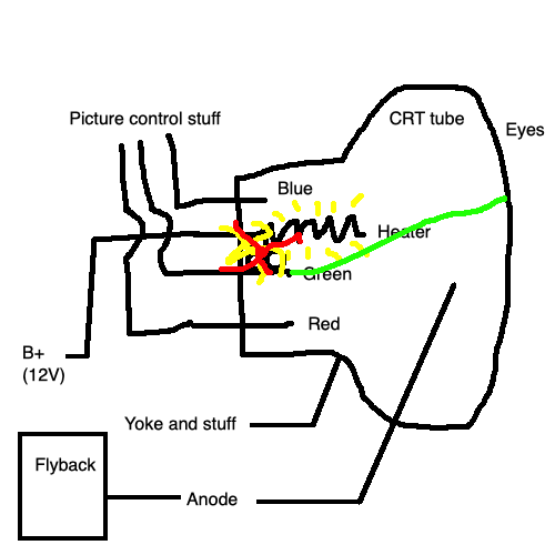
If some of that gunk were to short between the green gun and the heater, you could see something like this: a hyper-bright green. The diagonal retrace lines are always present in a raster image, but usually you only see them when brightness control is turned up too far, causing way too much voltage to be present on the gun. Say, a voltage like the +12V DC from the heater pin.
Having a short here would really suck. It would basically mean the tube is junk.
However, now that I’ve wasted your time by telling you all about this phenomenon, something other than an H-K short seems to be going on.
If you look closely at this other picture I took using my Pioneer MPC-LX100 Mac clone, you’ll notice that the retrace lines aren’t covering the full image. There appears to be a folded-over blue-green region that has them, and then the rest of the image is yellow-tinged, but clear. What’s going on?
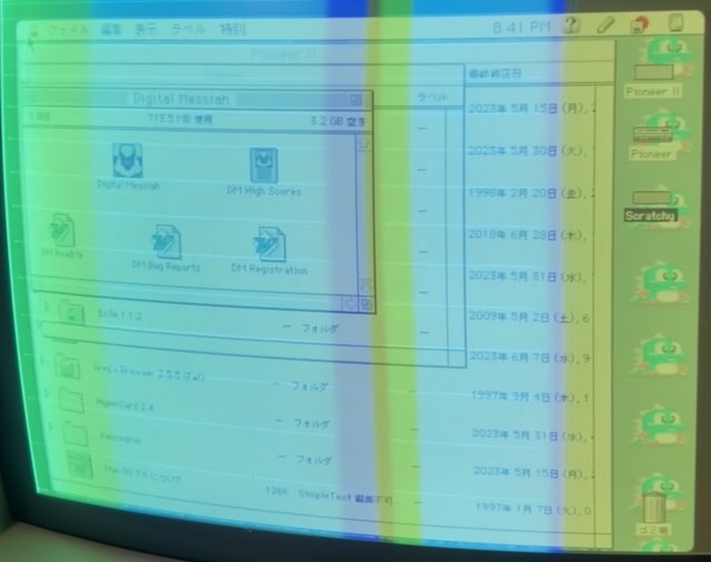
My first guess was that the monitor’s video cable might be bad. It felt loose when I put it onto the computer, and it has one of those screw-together clamps that always fall apart. I took it apart, and found that in fact the little U-shaped cable gland inside had come undone and fallen loose into the connector hood. I buttoned it back up tight, but the problem didn’t change.
You’ve Got Huge Guts
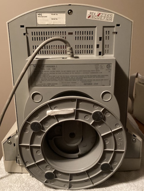
I opened the monitor up. This process isn’t too bad, except that only the outer screws seem to actually loosen the case. One of the ones in the middle, under the stand, doesn’t seem to be required in order to open the monitor. Out of caution, I put that one back in.
I found that wiggling from the back/port area upward sharply helped move the clips in the top front enough that the whole thing would just shrug off. For some reason, there’s a plastic panel on the back of the case that you can pop off using tension clips. However, the resulting tiny opening doesn’t seem to give you very good access to the pots on the neckboard, even if you remove the RF shield in the way. I’m not sure why they did this.
After the plastics were off, I was presented with a menagerie of 1990s RF-shielding techniques. There is an absolute ton of metal inside this monitor, and wiring harnesses running everywhere. And one oddly wet-looking spot on the bottom board in amongst all the dust.
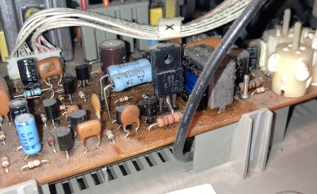
I also found a small fabricy piece of hard white plastic sitting on the bottom of the board, which is probably what was making that faint rattling noise when I moved the monitor around. It smelled kind of fishy, which made me suspect it might be the guts of a capacitor (they throw their wrappings very far when they explode, ask me how I know,) but I saw no evidence of any exploded caps inside the monitor, and it didn’t feel sticky like the inside of an exploded cap would. It will remain a mystery.
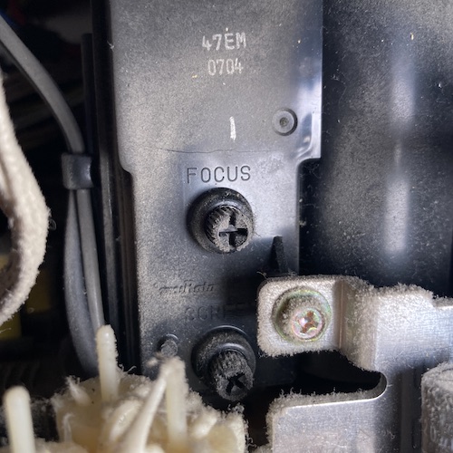
Uh oh, there’s a crack forming in the flyback transformer’s case plastic. I made a note to fix this later with the world’s best-named product, Super Corona Dope, but eventually this plastic will shrink further and make the crack worse. For now, I hoped that was the extent of flyback damage.
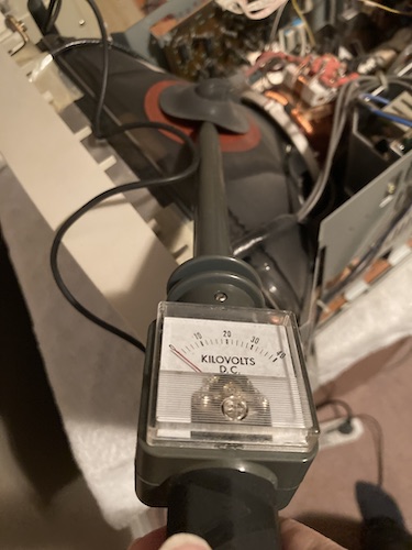
Since I’ve been doing a handful of CRTs lately, I bought a Heathkit 40kV high-voltage probe meter from eBay to help me discharge the tube. Supposedly, the internal resistor will help discharge the tube more gently, which is probably better for all parts of the system involved, including me. Hopefully this probe meter works, because it told me that there was no voltage on the tube. It had been sitting for a few days, so it seems likely it just bled off on its own.
Getting the anode cap off was really hard! The hooks on the clip are very short, so you can’t get any leverage on them. I ended up using my new high-voltage tester (which I sure hope works) to pry up the anode cap’s rubber and let me slowly work the clip to one side so it would eventually pop free. It still felt like I needed way too much force.
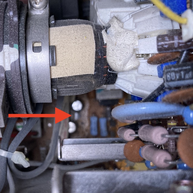
I could not immediately determine the source of the wetness on the bottom board without dismantling things further. Shining a flashlight directly down onto the bottom board, I saw an odd-looking pile of buildup that seemed to be parallel with the neck board.
One 1000µF cap in the power supply, near the fuse, looked like it had its skirt pulled way down, so I decided to start with the power supply. After studying the shields, I clipped all the zipties holding the input and output cables, removed three screws (one of which has a washer,) and slowly banged the power supply cage loose and up out of the case.
It’s nice when these things are labelled. Seems like NEC didn’t want to make their own power supply, so they leaned on a popular power-supply vendor: Delta. The benefit of them using something that’s sort of off-the-shelf is that it comes with a Delta part number (SMP-93AB,) and a listing of the input and output voltages!
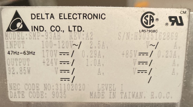
This power supply says:
- Input: 100-120V AC, 2.5A at 47-63Hz
- Output 92.85W with the following rails:
- +170V DC, 0.29A
- +85V DC, 0.23A
- +24V DC, 1.0A
In my limited experience, Delta supplies are generally a high-quality part, but they do fail like anything else. Especially in a constrained environment like a cathode ray tube monitor. It appears that NEC went in-house for the power supply in later models of the MultiSync 3D, at least in Europe.
The tube itself is an NEC, of course, with part number M34KBG23XX. This matches what the CRT Database has for the monitor.
Neck Board Inspection
The neck board is full of caps and it seemed like a likely suspect for dripping toxic goo into the board below. Unfortunately, it’s pasted onto the end of the CRT using silastic. This is a pretty common technique with CRT monitors, as it keeps the neck board from coming loose and causing damage during transportation. What isn’t common, at least in my experience, is the silastic getting inside the CRT connector. They sure put a lot of this stuff on here! It took me over an hour to gently cut it away from the tube so I could wiggle the tube connector off, and even more time to clean it out of the female tube connector on the neckboard.

Using the callouts on the back of the neck board as a reference, I checked for a short between the “H” (heater) pins and the RK, GK, and BK (Red, Green, Blue cathode) pins using my multimeter set to resistance mode. At no point did my multimeter pick up any resistance or circuit path at all, but I’m not sure if this is a legitimate way to test for this fault – I don’t have a big fancy tube tester.
So, no heater-to-cathode short after all: I drew those fancy diagrams for nothing. Phew! What is the problem, then?
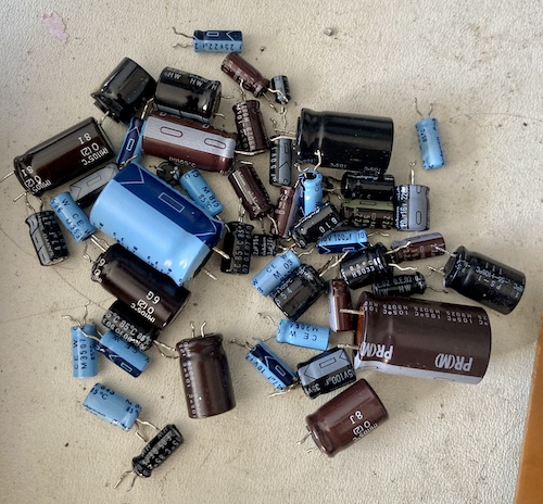
After spotting some funky-looking solder mask on the neck board, I depopped the caps in the vicinity of the tube socket and was met with a lot of fish stink. It was getting worse as I went along, so I ended up depopping the entire neckboard in order to test the caps out of circuit. Here, see for yourself:
Cap list:
| Callout | Capacitance (µF) | Voltage (V) | Series | ESR observed (Ω) | Good ESR2? | Comment |
|---|---|---|---|---|---|---|
| C912 | 220µF | 16V | KMC 7R? | 0.63Ω | No (0.40Ω max) | |
| C906 | 100µF | 16V | Rubycon SSP 590 | Open | No (dead) | Stinky |
| C903 | 47µF | 16V | KME | 2.4Ω | No (1.6Ω max) | Stinky |
| C902 | 47µF | 16V | KME | 3.0Ω | No (1.6Ω max) | |
| C901 | 47µF | 16V | KME | 2.7Ω | No (1.6Ω max) | |
| C915 | 2.2µF | 50V | Rubycon SSP 523 | Open | No (dead) | |
| C914 | 2.2µF | 50V | Rubycon SSP 537 | Open | No (dead) | Stinky |
| C913 | 2.2µF | 50V | Rubycon SSP 537 | >40Ω | No (dead) | |
| C924 | 47µF | 16V | KME | 2.4Ω | No (1.6Ω max) | Stinky |
| C928 | 1µF | 160V | Rubycon SH 146 | 5.9Ω | Yes (9.5Ω max) | |
| C905 | 4.7µF | 35V | KMC M | 3.6Ω | No (3.0Ω max) | Non-polarized! |
| C932 | 1µF | 160V | Rubycon SH 146 | 5.6Ω | Yes (9.5Ω max) | |
| C930 | 1µF | 160V | Rubycon SH 146 | 5.6Ω | Yes (9.5Ω max) | Near heat element |
All caps were 105°C rated.
The huge quantity of open (or nearly-open) 2.2µF caps is probably a pretty good smoking gun for poor video quality! Let’s take a look at where those caps are involved.
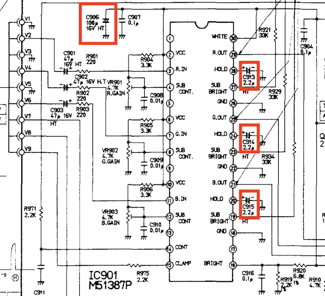
Three of these caps are attached to the “Hold” pins on the Mitsubishi RGB amplifier IC on the neckboard. The last one is a bulk filtering cap for the power supply on that IC. Yeah, leaving those pins effectively floating might cause some brightness issues. C906 also leaked so badly that it damaged the solder mask on the backside of the PCB, although thankfully no traces seemed to be severed. Scraping off the solder mask and then applying some clear nail polish will help preserve some reliability here, I hope.
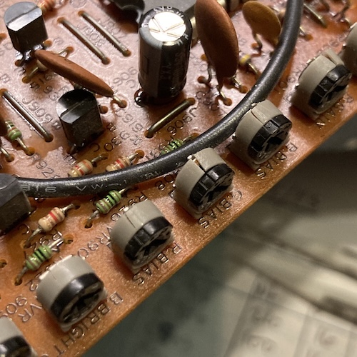
My job got a lot harder when I noticed that the adjustment pots on the neck board were either cracked, or starting to crack, or really cracked. Here’s Green Bias, which is almost as badly damaged as Red Gain down the board. If there’s one thing I know, it’s how bad pot can ruin a green CRT party. However, it wasn’t as bad as I had feared. All of the pots seemed to measure sanely (when cold, of course) on a multimeter, with the exception of “blue sub-brightness,” which ohmed out to 11.37kΩ when its red and green companions were just under 2kΩ (out of 22k.) That’s odd, but as you can see from the picture above, blue is clearly visible. I decided to leave it alone for now, and worry about the pots later, if I saw temperature-related problems or the loss of specific colours on the first post-recap test.
Power Board Recap
Before you can love another, you must first love yourself. It’s kind of like that for power supplies too. Before you can power an x-ray-flinging, rapidly-oscillating overgrown vacuum tube, you must first power yourself. If the power’s dirty, the operation of the monitor won’t be as good. Ignore the fact that I never went back and recapped the PC-TV151 after getting it to run… it’s too busy being used all the time.
Thermally, the power supply is in a good location. It’s at the top of the monitor, and it’s not too encumbered by shields. Delta did a good job positioning the heat-generating elements away from the huge electrolytic caps, which you’d expect because that’s their job. Chalk one up for outsourcing.
Because a bunch of caps looked suspicious on the power board – mostly pulled-down skirts and gently domed-looking vents – I started there. I pulled every cap out of circuit and ESR-tested them. This is difficult, primarily because the silastic goop that Delta/NEC used on this board was absolutely rock hard. It took me more time to cut through it than to desolder the caps.
Cap list:
| Callout | Capacitance (µF) | Voltage (V) | ESR observed (Ω) | Good ESR2? |
|---|---|---|---|---|
| C603 | 220µF | 35V | 0.17Ω | Good |
| C651 | 1000µF | 35V | 0.17Ω | Bad (0.07Ω max) |
| C652 | 47µF | 35V | 0.62Ω | Bad (0.35Ω max) |
| C682 | 100µF | 100V | 0.31Ω | Good |
| C693 | 47µF | 250V | 0.47Ω | Good |
| C606 | 4.7µF | 50V | 3.2Ω | Marginal (3.0Ω max) |
| C604 | 4.7µF | 50V | 3.0Ω | Marginal (3.0Ω max) |
| C681 | 220µF | 100V | 0.09Ω | Marginal (0.10Ω max) |
| C??? | 100µF | 250V | 0.22Ω | Marginal (0.20Ω max) |
All these are 105°C caps, of course. The last cap in the list is unknown callout because they globbed silastic all over the callout and I couldn’t get it off without destroying the silkscreen. A lot of the “marginal” caps are so because, although my ESR70 is calibrated, there’s always residue and general incompetence on the probes to worry about that could sway it by a few hundredths of an ohm.
To replace the silastic I ended up using regular old cheap hot glue from a hot glue gun. Is it neutral-cure? Absolutely not. Will it keep the PCB going for many years to come? Sure hope so.
Microcontroller board
The MultiSync 3D’s marketing material brags about its exotic microcontroller, which enables the set to display a wide variety of signals and tolerate the complex world of analogue malfeasance. In reality, this microcontroller is another mask-rom NEC “PCZ80-xx,” just like the ones used inside the PC-6001mkII and Mr.PC!
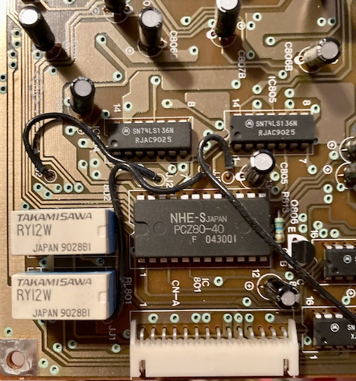
I would love to see a decap of one of these. From the name, I would assume that this is a Z80-based microcontroller with mask ROM, but it’s gotta be pretty fast if it’s processing video inputs, even with extra delay logic added on the sync to make up for it.
This board seems to mostly be covered in a variety of low-value but high-voltage 105°C capacitors, which I had lots of in my pile. There’s also two cute Takamisawa micro-relays for protecting the micrcontroller from whatever dumb crap you plug in. Otherwise, the board is nothing but a handful of connectors and some 74s for marshalling and buffering (potentially digital TTL) signals coming directly off the VGA connector to the microcontroller.
The microcontroller has some interesting unused pins, TEXT and INV, in the schematic. The former might be some kind of colour killer for high-resolution monochrome text? Not sure, but the MultiSync II service manual mentions that it has a “TEXT” switch which displays a single colour (white, amber, or green) against a black background. It may well be a holdover from that earlier design that was deemed to be an obsolete concern for the 3D. Front-panel buttons aren’t free, you know.
| Callout | Capacitance (µF) | Voltage (V) | Temperature | Series | ESR observed (Ω) | Good ESR2? | Comment |
|---|---|---|---|---|---|---|---|
| C802 | 2.2µF | 50V | 105°C | GE | 3.00 | Good (max 4.50) | |
| C803 | 10µF | 25V | 105°C | GE | 1.66 | Good (max 5.30) | |
| C835 | 10µF | 25V | 105°C | GE | 1.52 | Good (max 5.30) | |
| C808 | 47µF | 16V | 105°C | GE | 1.20 | Bad (max 1.00) | |
| C804 | 47µF | 16V | 105°C | GE | 1.39 | Bad (max 1.00) | Leaked |
| C805 | 47µF | 16V | 105°C | GE | 1.33 | Bad (max 1.00) | Leaked |
| C806 “B” | 47µF | 16V | 105°C | GE | 1.16 | Bad (max 1.00) | Leaked |
| C807 “B” | 47µF | 10V | 105°C | GE | 1.36 | Good (max 2.20) | |
| C806 “G” | 47µF | 16V | 105°C | GE | 1.12 | Bad (max 1.00) | Leaked |
| C807 “G” | 47µF | 10V | 105°C | GE | 1.36 | Good (max 2.20) | |
| C806 “R” | 47µF | 16V | 105°C | GE | 1.02 | Bad (max 1.00) | Leaked |
| C807 “R” | 47µF | 10V | 105°C | GE | 1.22 | Good (max 2.20) | |
| C809 | 10µF | 25V | 105°C | GE | 1.53 | Good (max 5.30) | |
| C810 | 10µF | 25V | 105°C | GE | 1.37 | Good (max 5.30) | |
| C811 | 2.2µF | 50V | 105°C | GE | 2.80 | Good (max 4.50) | |
| C813 | 2.2µF | 50V | 105°C | GE | 2.90 | Good (max 4.50) | |
| C820 | 47µF | 16V | 105°C | GE | 0.95 | Marginal (max 1.00) | Stinky, but no leak |
| C819 | 47µF | 16V | 105°C | GE | 0.97 | Marginal (max 1.00) | |
| C821 | 47µF | 16V | 105°C | GE | 1.05 | Bad (max 1.00) | Leaked |
| C812 | 2.2µF | 50V | 105°C | GE | 2.80 | Good (max 4.50) | |
| C814 | 10µF | 25V | 105°C | GE | 1.30 | Good (max 5.30) |
I would not have recapped this board normally. I’m glad I did, because a lot of the 16-volt 47µF caps were leaking. Notice that there are interesting suffixes on some of the caps: some sort of sub-circuit for the red/green/blue inputs, I guess.
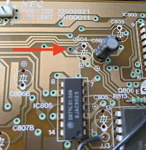
As I was pulling the caps, I noticed that one of the traces on the top of the board looked wrecked. Oh no! Did I somehow pull a pad? Luckily for me, this was just a chunk of super-hardened soldercrete dust from all the leaky caps that fell out of the gun. It wiped right off with a q-tip.
Annoyingly, I did not have any 105°C-rated 10µF 25V caps on hand, even after doing an order for this very same monitor! I ended up leafing through my supplies and going through the other boards’ cap lists to make sure that I hadn’t forgotten anyone else. Through the vagaries of parts catalogues and clearout prices, I ended up getting a bunch of obsolete-model very tiny 10µF 25V caps. Despite their tiny size, they were rated for 10,000 hours at 105°C, so I think I got a deal.
Main Board Party
Here’s where things get spicy. I had to unplug at least a dozen cables to get the mainboard free, and it fought me the whole way out. In the end, I prevailed, and now had the mainboard and neckboard on my desk. With better lighting and access to parts, I was now able to poke under some of the suspicious caps.
Some of the suspicious wetness looked to be around the caps near the Sanyo LA7835 vertical deflection oscillator, which must get very hot because it was screwed into a heat sink. As expected, both caps in the crevice of the heatsink had some evidence of leakage. C415 (100µF/35V decoupling cap on +24V rail) was leaking green goop, and C412 (100µF/35V involved in the “pump up” circuit) had a filthy dark wetness on its negative leg that definitely did not look good.
As far as I could tell, I wasn’t seeing vertical deflection problems, but it doesn’t take much to fix these suckers either. For another hobbyist, the leakage from these caps caused at least one vertical deflection problem, according to a post on Vogons in the recent past.
After the neck board, I decided to target-desolder the Rubycon SSPs for spot testing. Finding the ones on this board open, too, I decided to go to a shotgun recap strategy for the mainboard. This took a long time and produced a ridiculous amount of e-waste:
I held onto the good-ESR caps and put them into my scrap bin, for later prototyping or if I get really stuck and need a specific value right away. Everything else went to The Jar.
Owing to the massive expanse of real estate, a lot of the caps on this big ol’ main board are only 85°C rated, except for those exposed to heat-generating elements. NEC did a very good job managing thermals considering how much shielding they put on this thing3. Heat rises, after all. I ended up replacing everything with 105°C caps if I had to buy new ones.
As you can see from the cap list that follows, the mainboard has a lot of things going on! I spent a lot of time ripping caps off their shipping tape and slamming them home.
Cap list:
| Callout | Capacitance (µF) | Voltage (V) | Temperature | Series | ESR observed (Ω) | Good ESR2? | Comment |
|---|---|---|---|---|---|---|---|
| C526 | 22µF | 25V | 85°C | Rubycon CE | 1.48 | Marginal (max 1.50) | Stinky |
| C595 | 220µF | 35V | 85°C | Sanyo HW | 0.12 | Good (max 0.20) | Some dried leakage on bottom |
| C527 | 1µF | 50V | 85°C | Rubycon CE | 2.90 | Good (max 4.50) | |
| C2002 | 220µF | 35V | 105°C | KM | 0.18 | Marginal (max 0.20) | |
| C512 | 220µF | 10V | 85°C | Rubycon CE | 0.46 | Good (max 0.60) | |
| C536 | 10µF | 250V | 105°C | KME | 1.85 | Bad (max 1.40) | |
| C561 | 47µF | 35V | 85°C | Sanyo HW | 0.87 | Bad (max 0.70) | |
| C594 | 10µF | 160V | 105°C | KME | 2.30 | Bad (max 1.20) | |
| C542 | 2.2µF | 50V | 85°C | Sanyo HW | 3.10 | Good (max 4.50) | |
| C545 | 220µF | 16V | 105°C | Rubycon PS | 0.47 | Bad (max 0.30) | |
| C558 | 47µF | 50V | 85°C | Sanyo HW | 0.53 | Bad (max 0.50) | |
| C598 | 1µF | 50V | 85°C | Rubycon CE | 3.00 | Good (max 4.50) | |
| C525 | 470µF | 16V | 105°C | Nichicon PF | 0.18 | Marginal (max 0.18) | Discoloured PCB underneath |
| C522 | 220µF | 25V | 105°C | Rubycon PS | 0.56 | Bad (max 0.25) | Discoloured PCB underneath |
| C537 | 100µF | 160V | 105°C | Nichicon PR | 0.17 | Good (max 0.30) | |
| C2001 | 47µF | 35V | 105°C | Rubycon SSP | OPEN | No (dead) | Looks melted? |
| C410 | 470µF | 16V | 105°C | KMC | 0.30 | Bad (max 0.18) | |
| C412 | 100µF | 35V | 105°C | Rubycon SSP | 2.60 | Bad (max 3.00) | Stinky |
| C415 | 100µF | 35V | 105°C | Rubycon SSP | 1.72 | Good (max 3.00) | Leaking |
| C565 | 22µF | 160V | 105°C | Rubycon SH | 0.74 | Good (max 1.10) | |
| C540 | 22µF | 50V | 85°C | Rubycon CE | 1.73 | Bad (max 0.80) | |
| C593 | 1µF | 50V | 105°C | Rubycon SSP | OPEN | No (dead) | |
| C588 | 1µF | 50V | 85°C | Rubycon CE | 4.10 | Good (max 4.50) | |
| C426 | 1µF | 50V | 85°C | Rubycon CE | 3.70 | Good (max 4.50) | |
| C519 | 220µF | 10V | 105°C | Nichicon PR | 0.84 | Bad (max 0.60) | |
| C418 | 1000µF | 50V | 85°C | Rubycon CE | 0.06 | Good (max 0.10) | Suspiciously low ESR? |
| C563 | 47µF | 16V | 105°C | KME | 2.70 | Bad (max 1.00) | |
| C421 | 22µF | 16V | 105°C | KME | 3.00 | Good (max 3.60) | |
| C564 | 47µF | 35V | 105°C | Rubycon SSP | OPEN | No (dead) | |
| C422 | 47µF | 16V | 105°C | KME | 2.30 | Bad (max 1.00) | |
| C531 | 100µF | 16V | 105°C | Rubycon SSP | OPEN | No (dead) | Visible leakage |
| C159 | 220µF | 10V | 105°C | Nichicon PR | 0.75 | Bad (max 0.60) | |
| C161 | 22µF | 25V | 85°C | Rubycon CE | 1.49 | Marginal (max 1.50) | |
| C424 | 22µF | 16V | 105°C | KME | 2.50 | Good (max 3.60) | |
| C419 | 22µF | 50V | 105°C | KMC | 1.90 | Bad (max 0.80) | |
| C165 | 1µF | 50V | 85°C | Rubycon 259? | 8.50 | Bad (max 4.50) | Tiny |
| C166 | 22µF | 16V | 85°C | Nichicon N? | 2.50 | Good (max 3.60) | Tiny |
| C167 | 22µF | 16V | 85°C | Nichicon N? | 2.50 | Good (max 3.60) | Tiny |
| C183 | 10µF | 16V | 85°C | Rubycon 250? | 4.60 | Good (max 8.00) | Tiny |
| C408 | 220µF | 16V | 85°C | Nichicon RS | 0.34 | Bad (max 0.30) | Low height |
| C505 | 100µF | 10V | 85°C | Rubycon CE | 1.19 | Marginal (max 1.20) | |
| C407 | 220µF | 16V | 85°C | Nichicon RS | 0.36 | Bad (max 0.30) | Low height |
| C2003 | 47µF | 10V | 85°C | Rubycon CE | 1.77 | Good (max 2.20) | |
| C2004 | 47µF | 10V | 85°C | Rubycon CE | 1.55 | Good (max 2.20) | |
| C517 | 47µF | 25V | 85°C | Rubycon CE | 1.02 | Bad (max 0.90) | |
| C556 | 47µF | 50V | 85°C | Sanyo HW | 0.58 | Bad (max 0.50) | |
| C546 | 2.2µF | 50V | 85°C | Sanyo HW | 3.80 | Good (max 4.50) | |
| C518 | 10µF | 50V | 85°C | Rubycon CE | 1.99 | Bad (max 1.60) |
Almost all of these open caps didn’t seem to do anything particularly interesting to the signal:
- C2001 is a bypass cap located near the TP2001 test point, which is itself mentioned in calibrating the “high-voltage protector 1” circuit later in the service manual;
- C593 seems to be involved in filtering the power but not the signal to an op-amp for width control;
- C564 is the bypass cap on 24V power entry from the power supply;
- C531 is a bypass cap in the power supply section for the 2SA952 transistor involved in horizontal width control.
In other words, none of these should have dramatically affected the video signal when they failed, but NEC didn’t spend money on them for no reason, so replacing them was still the right thing to do.
Remember a couple paragraphs ago, when I placed a second order of caps for this set? Well… I forgot to order any 1µF/50Vs! Luckily for me, I had a bunch left over from the Tandy 1000SX power supply repair, and that small quantity just happened to be exactly enough to complete the job. Thanks, universe.
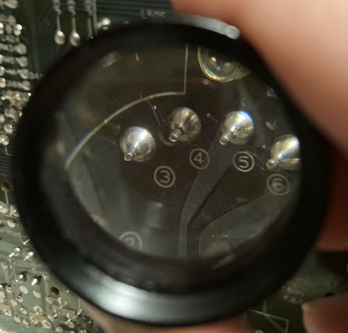
Pin number four on the flyback transformer didn’t look great, so I decided to reflow it. It’s a good thing I did, because the old, corroded solder was a bit ashy and clogged the desoldering gun when I pulled it out. I ended up reflowing the entire flyback transformer: as you can see, the adjacent pins didn’t look that much better. Come to think of it, I have actually reflowed the flyback on all the CRT monitors I’ve worked on thus far: the job feels like cheap preventative maintenance, and it’s a pain in the ass to get the mainboard out of this particular set, so I didn’t want to have to pull the mainboard again just to fix some solder joints somewhere down the line.
Reassembly
Now that I’ve replaced – count ‘em – ninety-one aluminum electrolytic caps, it was time to embark upon the project of plugging in all these cables again. This is one of those time-consuming and frustrating jobs, but I went slow and made sure not to leave any pieces of the puzzle undone. For this set, I also made sure to keep my cut zipties around, so I could keep track of how many more new zipties I’d need to reinstall to make sure I didn’t leave any harnesses dangling. I cut a lot of zipties to make a slightly easier route when reassembling, because otherwise I found that I was tying them in knots or big airplane loops that shortened their effective length.
I wish I had marked down which coarseness each screw hole took during disassembly, because there’s not much apparent consistency. Usually, I write with a Sharpie marker on the heat shield if the screw that goes there is somehow special, but I had misplaced my marker and didn’t want to interrupt the disassembly to go grab it. I am pretty sure I cut coarse threads into at least one fine hole, even going gently and using the counterclockwise “find a thread” trick. Oh well.
After putting everything back together, I had one leftover coarse short screw, and one missing coarse long screw4. This is probably because my method of screw holding (putting everything on a towel that fell behind the desk later) was not the best, as evidenced by the fact that a few weeks later, I found the missing screw under a piece of furniture. I could blame myself, or we could blame screw-stealing gnomes. Damn those gnomes.
Still, now the monitor was at last back together after weeks of trial, and it was time to fire it up on the Pioneer MPC-LX100 Mac clone once more, running Mac OS 7.6.1-J. We’ll have more to share about this weird computer later on, but for now:
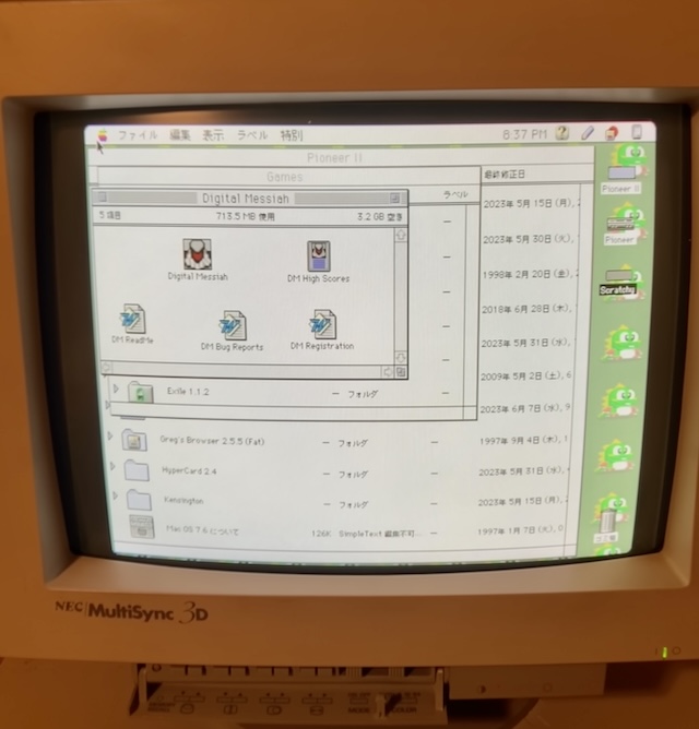
This picture was initially very far to the right, and very blurry. After toggling the “mode” switch, things seemed to improve in the fuzziness department, although my method of taking photos using the “long exposure” setting on my iPhone with the room lights on seems to be making them blurrier than they actually are in person.
For some reason, there also seems to be some bright “foldover” on the far right of the image, even when adjusted to all the way left. Even though the monitor is now working properly, I’m not super happy with the picture, as it feels like the black level is a little bit too high compared to the “background” part of the image, and the overall image still seems softer than I want it to be. Some more adjustments may need to be done, once I load a test pattern generator onto this Mac.
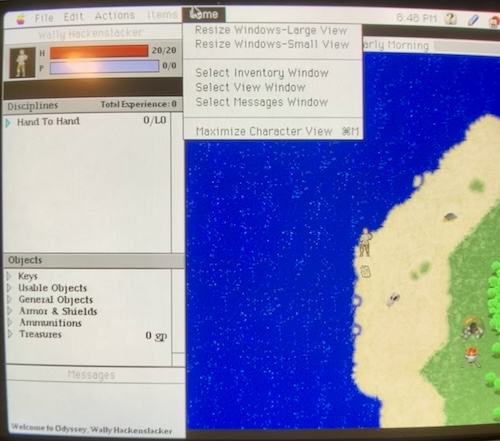
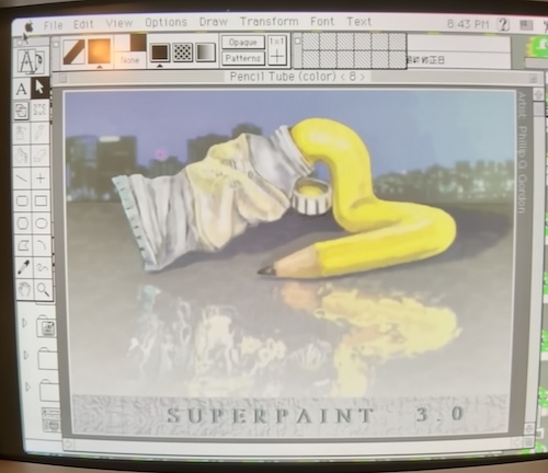
The curvature of the monitor took me some getting used to, mostly because the case of the MultiSync 3D looks like a mid-90s monitor rather than a 1989/1990 design. Text is very legible, even Odyssey’s tiny NPC dialogue boxes:

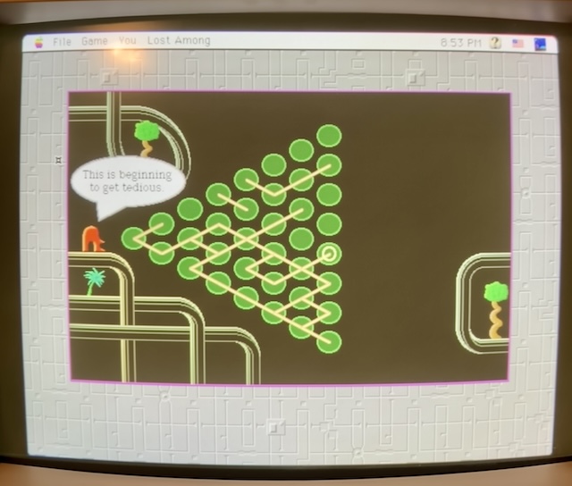
And one of my favourite puzzle games, System’s Twilight, looks great too:
More Input! More Input!
Of course, the MultiSync is not just a run-of-the-mill VGA monitor. The whole point of getting one of these weirdo things is to be able to play with 15kHz and 24kHz sources, as well as TTL-level digital RGB signals like CGA and EGA. So let’s figure those out now.
According to NEC, the shipping box of the MultiSync 3D was supposed to come with a 9-pin CGA/EGA adapter, as well as a Mac-to-VGA adapter. Those are long gone, of course. That’s not such a tragedy for the Mac side, as we’ve already got an adapter in use with the Pioneer, but I can’t even find a part number to try and do an eBay search on to get the CGA one. Good news, though, as the service manual should tell us how to make an adapter, and which pins to ground out in order to tell the microprocessor inside the monitor to switch into the appropriate modes.
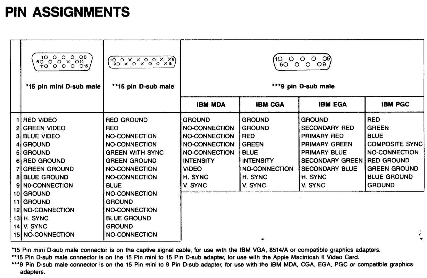
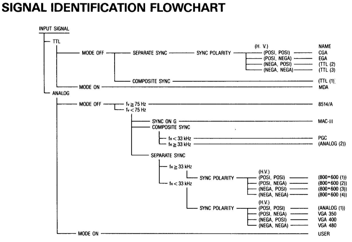
I expected to see some special diodes here, or even a grounded signal pin to help switch the monitor into the appropriate mode, but it seems like the monitor just uses different pins so it’s not confused about why someone is trying to drive the analogue input pins with a TTL-level signal. Very slick, and a good use of all the extra pins VGA has lying around. Figuring out if something is TTL or 0.7Vpp analogue is probably pretty simple, but guessing separate versus composite sync seems like some minor wizardry. The flowchart the monitor follows is here as well:
This table was a little confusing to me, because I couldn’t figure out why they were tying pin 1 of CGA (ground) to pin 1 of “VGA” (red.) Of course, it’s not really VGA, it’s just an HD15 connector. The signal going across it and into the monitor is whatever the microcontroller understands it as.
CGA and PC-6001mkII RGBI
To confirm, I did some searching and found another VCF thread about the MultiSync 3D and CGA. This one included a buzz-out of the official adapter. Thank you so much to chalackd for the post, and TamaMan for the confirmation.
For the purpose of preservation, this “adapter” is reproduced below:
| DE9 (CGA/EGA) | HD15 (MultiSync Input) |
|---|---|
| 1 | 1 |
| 2 | 2 |
| 3 | 3 |
| 4 | 13 |
| 5 | 14 |
| 6 | 5 |
| 7 | 15 |
| 8 | 12 |
| 9 | 10 |
This is a little bit unusual of a pinout, with oddities like VGA’s “red” pin connecting to ground, and CGA’s “red” pin connecting to VGA’s “blue” pin, but only if you think of the MultiSync’s HD15 connector as being a “VGA” connector, as opposed to a processor-driven “smart” multi-use connector that sometimes accepts the VGA pinout.
The DE9 was also used for EGA on later IBM PC systems, where pin 2 goes from being a ground to being a second bit of red colour, the former “intensity” pin becomes an extra bit of green, and an unused pin 7 turns into a second bit of blue, resulting in 6-bit digital RRGGBB colour.
The extra red, green, and blue bits expand CGA’s potential 16 colours (RGBI bits = 24 possible) to 64 (26) which is way more than anyone needs. I don’t have any EGA machines, so this is sort of academic for me, but it’s nice that the same adapter will handle both.
| Pin | CGA signal | EGA signal |
|---|---|---|
| 1 | Ground | Ground |
| 2 | N/C | Red 1 |
| 3 | Red | Red 0 |
| 4 | Green | Green 0 |
| 5 | Blue | Blue 0 |
| 6 | Intensity | Green 1 |
| 7 | Reserved | Blue 1 |
| 8 | H-Sync | H-Sync |
| 9 | V-Sync | V-Sync |
CGA is itself an extension from monochrome MDA, where the only luminance signals are on pin 6 (“Intensity”) and pin 7 (“Mono Video”) to produce an (optionally) 2-bit monochrome representation. One connector can carry three generations of digital video and not confuse reverse- and forward-compatible monitors too much. That’s good work there, IBM.
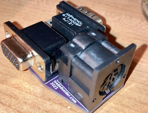
While I was at it, I figured I’d also make an adapter for the PC-8801mkII, Hitachi Basic Master, Fujitsu FM-7, PC-6001mkII, Sanyo MBC-555, and all the other 8-pin DIN Japanese TTL RGB systems I have lying around that I’ve forgotten about. I wired these pins into basically the same signal path as the RGBI pins of the CGA connector, as you do when you’re in the neighbourhood already.
Certainly a lot easier to set it up with this monitor than it is to source more 8DLPMS connectors in order to feed the PC-TV151.
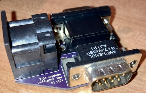
It looks pretty awkward. I guess any hydra would.
I went right ahead and tested it on the Tandy 1000SX, where I found out that it didn’t fit past the thick plastic rear of the computer:
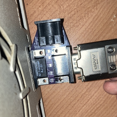
It is hanging up on the little piece of PCB I left behind so I could put some silkscreen on it. Once again, pride comes before the fall.
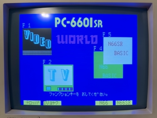
I also strapped a DIN8 to it to test it with my NEC “Mr.PC” PC-6601SR, which also didn’t work. If I plugged and unplugged the adapter while the set was turned on, I could hear relays galloping inside the monitor. I wished that I had traced out the signal board better when I had it outside of the monitor, and started to get a sinking feeling that I’d wired something up wrong and the monitor was going into protection.
In the meantime, I tested the monitor with my usual 150-ohm “dropper” VGA board that I designed for the PC-8801mkII, to see if the set could sync to 15- and 24kHz analogue sources:
The 15kHz PC-6601SR displayed great, as did the 24kHz PC-9801UV2:
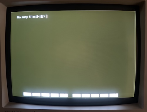
It did quite well, although stuck in only eight colours for the 66SR. Nice work, set. One item of concern is that the 9801UV2 raster’s background seems to be extremely bright and folded over on the edges, which makes me think I might need to adjust the screen voltage, the text is very sharp (trust me on this: ol’ shaky hands here needs to use a tripod.)
I noticed that something suspicious was happening on what I thought was the intensity pin. I ended up realizing I accidentally plugged in the Ys pin, which on the 6001mkII is +12V, but on the 6601SR, it’s barely 4V and it seems to have a sort of clock output on the scope. It seems like the 66SR RGB pinout is not exactly the same as the 6001mkII, which makes me wonder what else is different.
After realizing I once again put a DIN in backward, I cut and bodged the digital RGB adapter to flip the DIN connector over, and this produced a viable and sharp result in 16-colour mode:
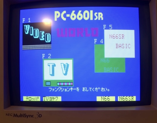
It is difficult to tell on the PC-6601SR startup screen at a glance whether there truly are more than eight colours, so I did what I should have done a long time ago and wrote a 16-colour demo for the PC-6601SR to test colour expression:
1 REM PC-6601SR colour test program
5 SCREEN 2,2,2:CLS
10 FOR C=1 TO 8
20 COLOR C
30 LINE(C * 30, 0)-((C+1)*30, 99),,BF
40 NEXT C

50 FOR C = 8 to 16
60 COLOR C
70 LINE((C-8)*30, 100)-((C-7) * 30, 199),,BF
80 NEXT C

100 IN$=INKEY$:IF IN$=""THEN 100
Unfortunately, I forgot that my eternally-incomplete PS/2-to-PC6601SR keyboard adapter currently did not support commas, so I had to quickly bodge up the firmware to work properly5. Such is the junk life.
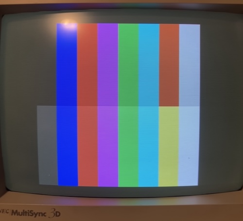
Anyway, you can see clearly that in “16” mode, the MultiSync 3D does indeed receive 16 colours. Intensity is working!
Unfortunately, if you compare it to my earlier picture from the PC-TV151, the PC-6601SR palette is a lot different from the IBM CGA palette which is in use by the MultiSync 3D here (there’s a dark brown, and all the colours are way too bland.)
The reason why only occurred to me at this point: PC-6601SR digital colour is not derived entirely from “full red plus full blue;” it’s an actual hand-picked, hardcoded palette inside the PC-TV151 to make these nice pastel colours such as the pleasant teal for “light green.” That’s the kind of thing you can get away with when you make the computer and the monitor at the same time.
For most of my purposes, this monitor will still work great with the PC-6601SR, and if I want authentic colour the way NEC intended, I can dig out the PC-TV151 instead!
The idea of the colour palette being controlled by microcontrollers, as they are in this monitor, is an intriguing one for sure. I don’t know if NEC sold this same monitor in Japan, but they could have easily made a mask-ROM spin to do “PC-98 colours” instead. This is one of those subtle traps you can fall into when trying to interface different regions of hardware together, even if it was all from the same manufacturer.
Apple IIgs
I also ginned up an Apple IIgs adapter, because at the time I was getting really into that uniquely rad old system. This video output is mostly the same pinout as a Mac adapter, but the Mac’s sense pins end up going to -5V and +12V rails on the IIgs, so I decided it would be safer to make something where those pins were not connected at all. The IIgs horizontal sync is also only 15kHz, so most uni-sync early Mac CRT monitors aren’t able to sync to it.
TULARC also provided the info that the MultiSync II would work great just connecting the Apple IIgs’s composite sync to the horizontal sync input on the monitor, so I did that, roughly following the VGA pinout as the MultiSync II has a DE9 connector instead.
Unfortunately, when the adapter arrived and I tried it, the monitor didn’t seem to display anything.
Second version of the adapter also didn’t work, where I tried to short fewer pins to ground.
Some rando on slashdot back in 2002 mentioned this:
The Second Sight worked on the IIe as well, though most of ‘em more than likely ended up in IIGS systems. My understanding was that it mostly worked, but had a few issues (IIRC, it didn’t do fill-mode SHR and might’ve had problems with 3200-color mode). I ended up eventually tracking down a VGA monitor that’d plug directly into my GS instead and work with its slow refresh rate (60 Hz vertical, 15.75 kHz horizontal)… an NEC MultiSync 3D, which works great through the “Mac adapter” that came with it. As an added bonus, it’s compatible with everything else around here with a VGA port.
Okay, I’ve got a Mac adapter, just not the one that came with the MultiSync…
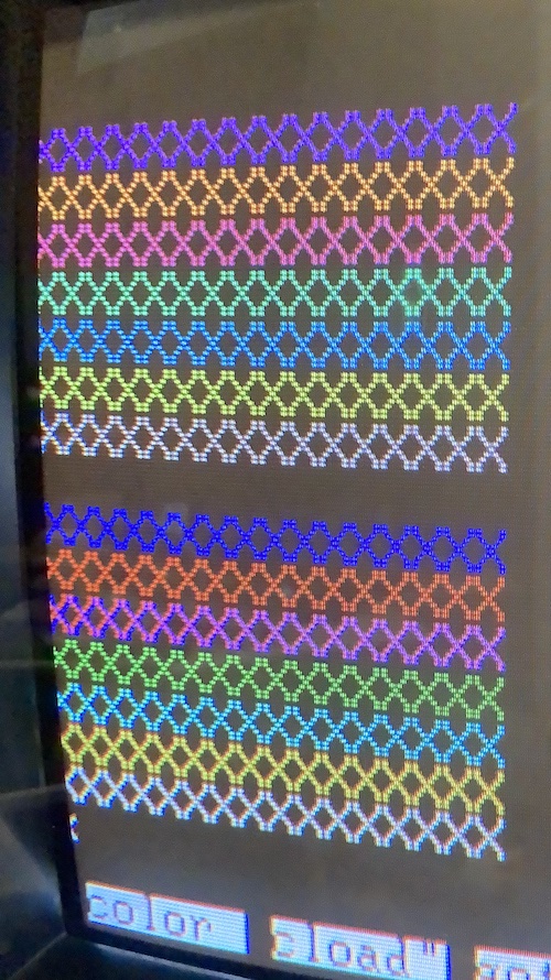
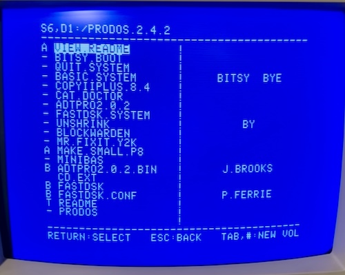
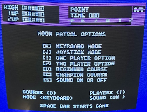
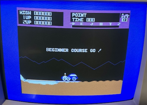
On a hunch, I ended up jumping the shields of the connectors together, as the IIgs monitor’s manual’s pinout section calls out the shield of the connector as both significant and separate from the colour grounds. This worked, and I was soon able to enjoy ProDOS and Moon Patrol:
Here’s what that adapter looked like after the bodge, if you care:
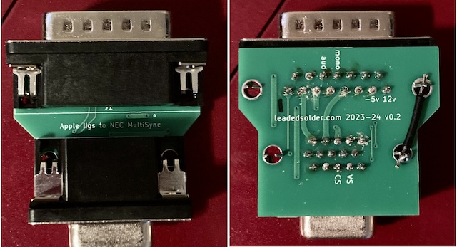
Nice.
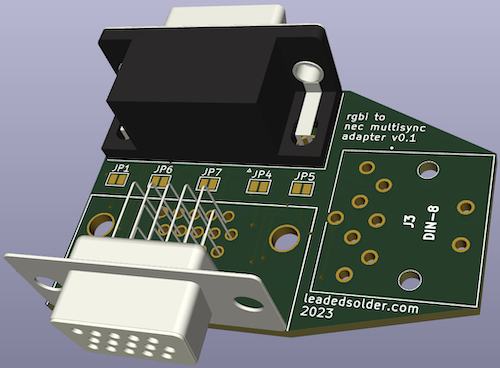
You can download and make the adapters for yourself:
| Adapter | Download link |
|---|---|
| Apple IIgs | leaded-solder/apple-iigs-nec-multisync-3d-adapter |
| RGBI to MultiSync (PC-6001mkII, Tandy, CGA) | leaded-solder/rgbi-to-multisync |
Conclusion
That’s all the fun I want to have with the NEC MultiSync 3D in this article; as you can imagine, I am tired of typing out the words “MultiSync 3D.” I’m glad that my long-shot of recapping the entire set paid off. This is yet another piece of evidence that everything Japanese from 90-91 (at least) with Nichicon low-ESR capacitors is in need of a re-cap to restore functionality.
Not everything is perfect with this monitor: there’s a bit of unpleasant fuzziness when the Pioneer is driving it. I’m not sure if this can be fixed with the Focus adjustment on the flyback, and I’m also not sure why it seems perfectly sharp when using lower-resolution machines.
I also need to do some adjustment and calibration with the levels, as all but the absolute lowest setting on the “contrast” dial is way too bright. This might (should) involve me building a SCART adapter and using 240p Test Suite.
For now, though, it’s a very powerful monitor that should be reliable for many years to come, and I’m grateful for the experience fixing CRTs that it’s given me. Now onto all the other broken CRTs I’ve bought since then…
Repair Summary
| Fault | Remedy | Caveats |
|---|---|---|
| Green “Northern Lights” display overlaying video | Replace neckboard caps as many failed open and most failed ESR test, causing amplifier IC to read from open pins. | Other caps on mainboard also failed, which makes it hard to isolate a specific failure. |
| Crack in flyback transformer. | Not fixed at this time. | |
| Crack in several neck board pots. | Not fixed at this time. | |
| Fine details blurry on Mac 640x480 source. | Not fixed at this time. |
Update History
- 2025 April 15: Zhinu correctly pointed out that I actually have 91 caps listed, not 87. I regret the error.
-
You might have heard of a CRT rejuvenator, which is a gadget that basically heats up the heater to a high level and then bangs on the guns to try and burn off the gunk. It also unavoidably burns off the plating on the cathodes in the process, which means that you’re still sacrificing some tube life for a temporary reprieve. You can also completely murder the heater in the process, which causes that colour to not work at all. However, rejuvenators can clear a heater-to-cathode short through this method. ↩
-
I used this worst-case ESR table and also this one. This table is a “standard,” which means it is certainly not true for all capacitors, or even for modern capacitors, but is good enough for my monkey work. ↩ ↩2 ↩3 ↩4
-
This is only a JC-1404HMA-1. Model 2, the MultiSync 3DS, has even more shielding! ↩
-
I did eventually find the coarse long screw, inside a different system that was supposed to have the coarse short screw in it. They briefly shared the bench while I was waiting for parts on the MultiSync. Corrections have been made to ensure that this kind of cross-breeding of screws does not happen in the future. ↩
-
In the midst of this bodging, I was unable to reprogram the Arduino and started freaking out, until I remembered it was an Arduino Mini and not a Nano like I previously assumed. I gotta get this adapter into a PCB already. ↩