Why, you three-bit machine...
Tags: computer nec pc-tv151 pc60 mr-pc pc6601sr video crt repair
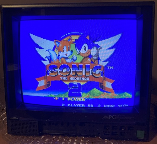
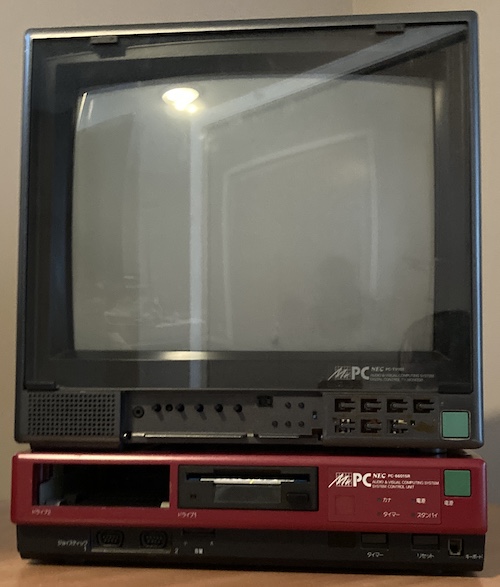
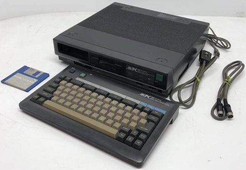
My NEC PC-6601SR “Mr.PC” has been a nearly permanent resident of my desk ever since it was repaired. This beautiful red computer works okay with a regular old VGA LCD monitor. So why did I pay a fortune to import a CRT monitor from Japan? There are two reasons. For one, it is the NEC PC-TV151 monitor that’s supposed to go with this computer. Also, it’s broken.
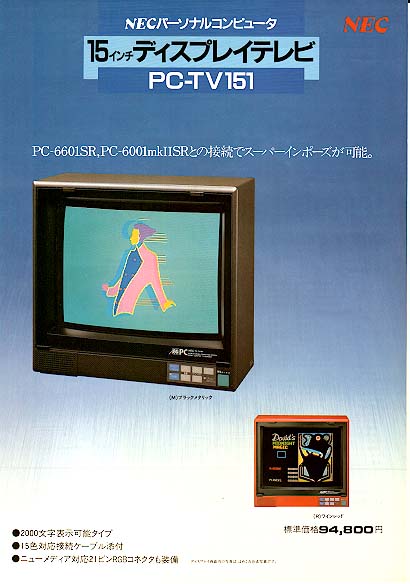
(Ad retrieved from the P6 Library List. Thank you for the excellent resource!)
Background
As I’ve gone into detail in previous posts, the NEC PC-6001mkII and onward use a special “15-colour” digital RGB mode.
On the PC-6001, and most other computers that use digital RGB, colours are represented by the presence or absence of a +5V TTL signal on the red, green, and blue pins. This produces 23, or 8 potential colours:

Starting with the PC-6001mkII, NEC added an “intensity” pin. If you’re familiar with IBM CGA or the Commodore 128 RGBI, this is the same idea. You can think of it is a “shift key” for the colour:
Notice that, while 24 = 16, it is referred to as “15 colour.” That’s because “bright black” is considered to be the same colour as “dim black1.” This is coincidentally the same colour depth as on the TI TMS9918 VDP, although that chip has a more muted colour palette.
While I made a perfectly good 3-bit RGB adapter using some 150Ω resistors, and I’ve used it on a surprising number of Japanese computers since, that’s only half the colours. I still needed something to mix in the intensity bit to get the full experience.
I’ve tried a lot of things, and I haven’t written them up before now since they all had flaws:
- RGB to HDMI (worked great, making a custom palette was awkward;)
- Handmade 74 conversion chains into a resistor ladder “DAC;”
- Using a ROM instead of 74 logic to decode colours (ROMs are slow;)
- An Raspberry Pi Pico-based RGBI-to-VGA adapter (more on this soon;)
I was never happy with any of the converter dongles, mostly because they always needed an external power source, felt like they were copies-without-understanding of someone else’s circuit, or they had other fidelity issues. If only there were some way to display the full 4-bit colour range on my PC-6601SR, and it would be nice if it also allowed me to use all the other cool video features of the computer as well.
It’s amazing you can still find an original PC-TV151 monitor, huh?
What is the PC-TV151?
Let’s do a little history lesson about 1980s Japanese megacorporate structure. If you’re good, we can get some ice cream on the way back.
NEC was getting excited about personal computers. Whereas previous “little” computers like the NEC TK-80, TK-85, COMPO-BS/80, and PC-8001 had been ignored by NEC’s more profitable “big” computer division, the plucky Microcomputer Sales Division, part of the Electronic Device Group, moved onward. Their strategy was to sell directly to individual engineers, and then later found out that all kinds of scientists, students, and weirdos also wanted their own computers, as limited as they were in comparison to the big guns.
Those computers the Electronic Device Group designed were constructed by New Nippon Electric, and they even formed their own specialist store, the NEC Bit-INN in Akihabara, to sell and educate about them. It was a big success.
In 1981, NEC split responsibility for developing personal computers into three divisions:
- Electronic Device Group (PC-8001, PC-8801, later PC-100;)
- Information Processing Group (PC-9801;)
- New Nippon Electric (PC-6001, PC-6601) – the hero of our story.
As you can imagine, making so many models of computers at the same time was very confusing, and caused rivalries and sales friction. The same retail outlets were being approached with three different salesmen and wildly different products, all “from NEC.”
In late December 1983, NEC chose to merge all the 8-bit machines into NEC Home Electronics2 (previously New Nippon Electric,) which would eventually kill off the PC-6001, PC-6601, PC-8001, and PC-100 in favour of the PC-8801 series. Information Processing would go on with the then-16-bit PC-98013.
Before all this happened, before home computers were even a twinkle in the eye of crazy people, there was something else that New Nippon Electric made: televisions4. It made natural sense for them to go on and make their own computer monitors as well – monitors have an (in theory) higher quality tube, and one that you can charge a greater margin for than a consumer TV. One of those monitors is the beautiful NEC Character Display, something so period-correct that I’d love to own one of them even if it didn’t work.
Although it is difficult to get a primary source on the reasoning behind any of NEC’s decisions, it seems impossible to discount the similarities between the Mr.PC and the Sharp X1, Sharp’s own Z80-based home computer line which beat the PC-6001 hollow in terms of sales. Let’s look at the overlap:
| Feature | Mr.PC | Sharp X1 |
|---|---|---|
| Case colour | Red, black | Red, black, white, grey |
| Vaguely VCR-shaped | Yes | Yes, most of the time |
| Monitor also a TV | Yes | Yes |
| Computer graphics superimpose over live TV | Yes | Yes |
One can imagine someone from the PC-6001 team getting a meeting with their counterpart from the monitor division, and then jointly becoming righteously angry at the Sharp X1’s television tuner and superimpose features. Even the MSRP of the PC-6601SR (¥155k) is identical to that of the original X1.
It’s not clear if NEC knew what they were getting into, though. The Sharp X1 turbo came out a month before the PC-6601SR was released, which surely must have made things more difficult if the previous model was in fact NEC’s benchmark. With the MSX chipping away at the low end, the 9801 dominating the high end, and the X1 in the exact same market segment, it was no doubt difficult for the 6601SR to establish a good installed base.
Here’s where my glowing tube friend comes in. With the release of the PC-6601SR, the PC-TV151 became available. According to NEC, it was available as a ¥94,800 option at the time of purchasing, but in the course of my searching, I found out that at least one person wasn’t allowed to buy the monitor separately from a PC-6601SR.
Don’t get too excited by that word “monitor,” however – the 0.49mm dot pitch is sharper than some budget options, but it’s not a high-resolution monitor, even for early 1985. Even NEC’s own specs claim it’s only a 200-line display, meant for 80x25 text at most.
All of this is to say that the PC-TV151 is the monitor that is supposed to come with the PC-6601SR computer, and combined with the infrared keyboard/TV remote, they form the “Mr.PC” home computer system. Like Voltron.
Getting It
Blog friend queuebert from the excellent Japanese Vintage Computer Collection blog had purchased this PC-TV151 before me. He plugged it in, tried to turn it on, and it didn’t work. Then he stuck it on Yahoo! Auctions to try and earn money for his crippling Casio FP-1100 addiction, and bought another PC-TV151 to replace it.
After he gave me a heads-up that it was listed, I was intrigued. I’d bought stuff from him before through the usual package proxy (a MyCard of Chack N’ Pop to test out the Soggy,) so I figured I would bid on this one too. Everything looked good in the pictures, and he assured me that there was nothing rattling around inside, loud noises, or scary burning smells when plugged in, so I went for it.
There was more bidding interest than I thought in a monitor that didn’t work. Having actual competition for this thing made me feel a little better about my own bidding. Maybe it was a commonly known problem! I won it for ¥3200.
Of course, when the shipping bill came due, that was a whole other matter. I sent it along with some little friends (Sega joysticks, Pioneer keyboards, the like) to help amortize the shipping costs, but this was one expensive gamble.
Investigating the PC-TV151
While I was waiting for the big Japan Post boat to come and deposit my PC-TV151 on my porch, I had lots of free time in which to do some research. Namely, I wanted to know what inputs this thing had, other than PC-6001mkII RGBI.
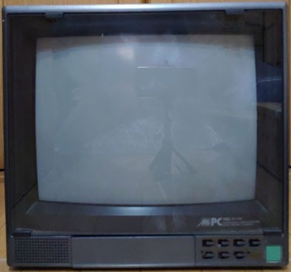
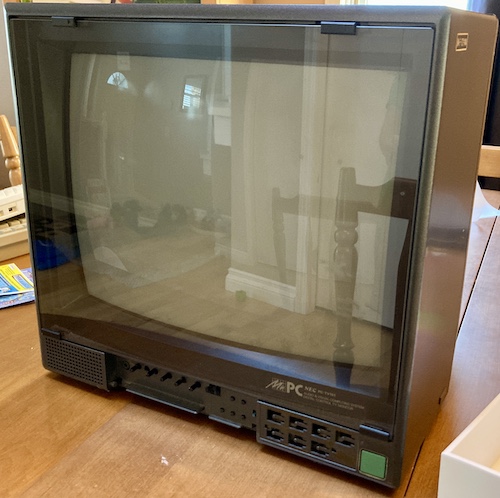
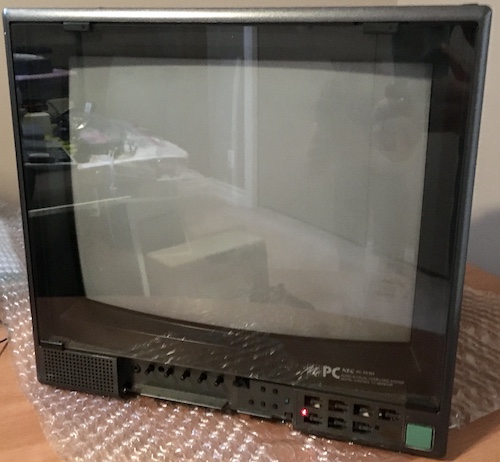
Around front, it looks like any other NEC TV of the period, albeit with a pretty green power button and the “Mr.PC” grid logo. There’s some buttons, but the sticker that tells me what those buttons do has fallen off. Behind a front panel is a bunch of controls, some obvious, some bizarre.
On the back is where things get really exciting. Most consumer TVs of 1985 would not have featured a JP21 analogue-RGB port, much less a JP21 input that can be output onto composite for video capture. During the course of my research, I found at least two bulletin-board posts claiming it was used by hobbyists to capture high-quality RGB video from arcade boards to VHS.
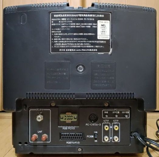
There’s a lot of ports here. Let’s review:
- Japanese terrestrial television (both coaxial VHF and fork-type UHF;)
- Digital RGB5 (with a switch to toggle between 8- and 15-colour mode;) through a D8A2-style connector, more on this in a bit;
- Analogue RGB through a JP21 connector;
- Remote control of the monitor by an attached computer – controls superimpose/titler, channel changing, VCR timer, etc;
- Composite video and audio in and out
That’s a lot of inputs! I figured that, in addition to being the mate for my Mr.PC, it would probably have the makings of a great test monitor.
Naturally, being a TV of the 80s, the PC-TV151 also has a built-in speaker. Its design language is sort of broadly similar to some NEC TVs I’ve seen of the era, which gave me hope that most of the parts inside were common, especially since I couldn’t find schematics (or even repair blogs) for the PC-TV151.
Arrival
When the TV-151 arrived, I was brimming with joy that it hadn’t been shattered into a million pieces inside the bag inside the box.
In fact, it looked pretty good. The only damage that I could tell was this broken-off tab from the front panel cover, which may well have been my own fault when unwrapping it:
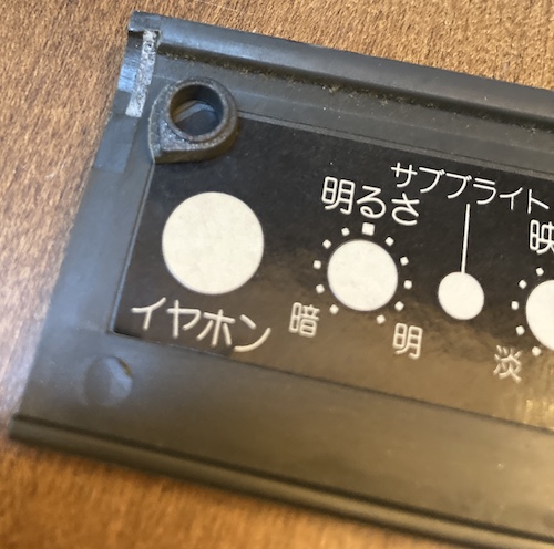
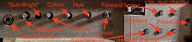
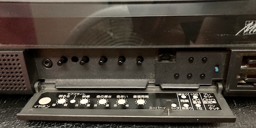
Looks repairable! I’ll definitely need this door, because in standard NEC fashion, it has a sticker on the inside of the flap that describes what all the controls do, rather than silkscreening or moulding them into the front of the TV. There are a ton of buttons and knobs in here, as well as a mysterious switch:
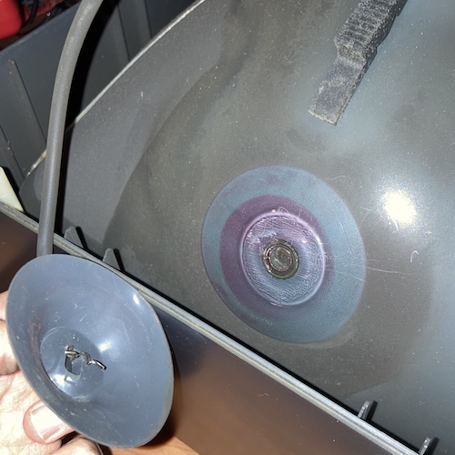
Once I was finally looking at the monitor in person, I noticed a couple other things. There’s a weird circular mark on top of the set that’s also in the auction photos. My best guess is that this was some kind of hot beverage, or maybe an antenna suction cup, placed on top of the TV. Something melted the plastic, either way, but it’s not that bad.
The power button felt weird, like it wasn’t able to click all the way. I began to vibrate with hope that this was the source of the problem.
As I said before, the control buttons on the front of the TV were unlabeled. They used to have a sticker explaining what they did over top, and without them it was going to be a matter of trial and error to figure out their functions. I ended up looking for photos and found this one blurry picture from the Beep blog that I was able to blow up just enough to be barely legible:
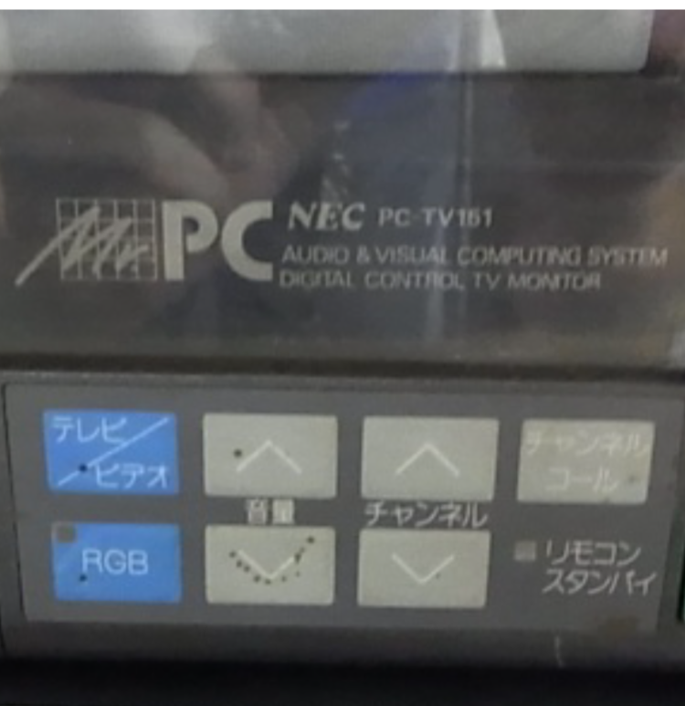
With some guessing and checking, I was able to figure out what these probably read in Japanese. After translating that to English, the functions of these buttons appear to be something like:
| TV/Video | Volume Up | Channel Up | Channel Call (Recall?) |
| RGB | Volume Down | Channel Down | Remote/Standby light |
I’ll make a new sticker to replace the missing one soon, once I figure out what material it’s supposed to be.
Naturally, the next thing to do is to open the set. I wanted to know right away if the CRT were necked, or if there was a nest of venomous cobras inside. Because of their coiled shape, a snake infestation can cause all kinds of power supply problems – a phenomenon known as squamate induction.
I didn’t find any snakes, but I did find a crack near this big-ass thing called an STR3115. Based on the Sanken brand, I assumed that it was:
- A power-supply related thing;
- Probably broken.
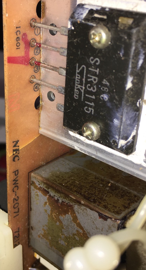
I looked around it, and the crack didn’t seem to sever any traces. It also stopped at a hole drilled into the board for another component. A little plastic standoff for the board was wobbling around inside the case, which had most likely broken its little clip and let the board jump around inside the case. Based on the appearance of the crack, it had happened a long time ago.
The CRT looked like, well, a CRT. Nothing necked, nothing scorched, and the yoke pins looked fine too.
In general, I’m used to seeing a lot of dust and hair and grit inside a television set. This one didn’t have that, only a fine layer of black carbon soot.
Maybe someone took the back cover’s invitation to open it up and clean it out to heart:
The back cover is held on with these clever screw tabs. Not only do they make the cost of the front cover cheaper, but they provide a lot of reinforcement that will help keep the thin case of the television from distorting. They probably couldn’t use metal inserts here, either for cost or for high-voltage isolation reasons.
There are seven screws in all holding the top case on: two long coarse ones on top, two short coarse ones on the bottom, and three short fine-thread ones holding the back cover to the port board.
Testing
I plugged the TV into the wall and tried to turn it on. It didn’t turn on – no lights, no high-voltage sound, no static feeling, no heater visible through the vents. I tried a few other little tricks, like “sneaking up” on the power button and surprising it, wiggling the power button, shaking the power button while plugging it in. Shockingly, these techniques failed to produce results.
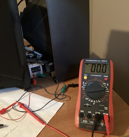
Not knowing what to do next, I checked the cord for continuity to see if it was dead shorted (why would it be shorted and not knock out the breaker it was on? I can only assume I was driven momentarily insane.)
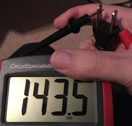
The resistance between the two prongs of the power cord is 143.5Ω, which is less than I would expect, as most other things I tried – even those things with standby circuits – just reported “open.” Flicking the power switch didn’t change this number. That’s weird, but doesn’t tell me anything.
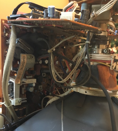
Disassembly
I laid the set aside for a little bit to work on other stuff, and also to work up the guts to start figuring out what was wrong with the set. Taking one of these suckers apart needs a lot of space, both for the TV itself and for all the various boards and guts and wiring harnesses that splay out from it as you dismantle it.
This TV has so many wiring harnesses. In fact, it was the primary annoyance when working on the board. Finally, after some fighting, I was able to release the lower board and start looking at it.
When it was time to discharge the CRT, I used a flathead screwdriver and an alligator clip to the dag (ground) spring. I didn’t get a click or a zap or anything, which makes sense if the TV didn’t work.
I went through the usual basic checks:
- Anything exploded?
- Any obviously broken solder joints?
- Anything burned up?
- Any cap leakage on the board or cap legs?
- Any broken or frayed wiring harnesses?
- Fuse okay?
Nothing doing. This was going to require some actual diagnosis! What a bummer.
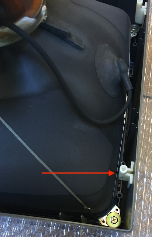
Finally, I determined that there was poor continuity between the poles of the power switch on the front panel. Gotcha!
Getting the panel out was a little more work. There was a lot of nasty crumbled-up foam that used to be used for sound deadening, and I broke the tab on one of the plastic lower-board mounts trying to remove it.
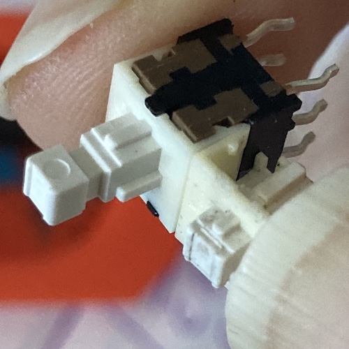
Sure enough, the power switch didn’t have any reliable continuity when clicked. Because it was a six-pin toggle switch, I assumed it was a DPDT-style switch, which should work something like this:
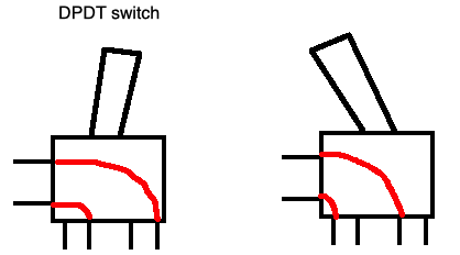
Instead, it just wasn’t. When toggled, the right-side inner pin was not continuous with either outer pin. So I desoldered it and took it apart, at which point the spring popped out, and the entire contents of the switch exploded into my carpet before I could get a good look at how it was put together. Crap.
That said, the parts I was able to recover looked worn. The metal bits had most of their plating gone, there was no grease inside, and the plastic “clicker” mechanism that toggles the switch was badly worn out. Time for a new switch, either way.
I wasn’t able to figure out what switch it used. There were no markings on the body or interior of the switch. The only thing I figured out is that the NEC PC-TV351, a successor PC/TV monitor (but one capable of 24kHz) had an identical front and rear panel, including the power button. Unfortunately, that didn’t help me – still no schematics, power button listings, or repair blogs about that monitor.
At this point, I went nuts and started ordering every DPDT toggle switch that looked similar. It didn’t cost me that much, because AliExpress is always willing to sell you bags of intricate mechatronic assemblies for like a dollar or two.
On eBay, I found a vendor selling a bag of 100 Alps SPPH230100. This felt like a good bet to me, because NEC liked to use Alps stuff in their equipment. I ordered it from the US, and it took longer to arrive than the AliExpress stuff did from China.
When each order of these switches arrived, I tried them all. Most didn’t fit. Finally, the Alps switches did fit, and they looked pretty good.
I sacrificed a new Alps switch to compare it to the few parts of the old switch I saved. Everything was dead-on: the toggle leaf was even the same colour.
The only thing is that the end of the Alps switch was longer than that of the switch I had removed. So I lopped off the end of the Alps switch with a pair of side cutters. Problem solved!
Now I got a confident continuity test on the board whenever the switch was toggled. Time to try out the new power switch!
Before reassembling, I hauled the whole mess out to my garage to blow it out with my XPower blower. It did a good job of knocking all of the dust bunnies out of the board and foam out of the case. Then, I dutifully set myself to the half-hour job of reassembling the TV, cable by cable, constantly worrying about bumping the neck of the tube.
With the board reinstalled, the power button feel wasn’t that great. Maybe it really did need the nub on the end after all? Even so, it still worked. Let’s test.
Test Fire One
With a fire extinguisher on hand, I prepared to fire up the TV for the first time.
Friends: it didn’t work.
However, my new Kill-A-Watt (purchased just for this project) reported it was pulling 80mA when the power switch was toggled, and 10mA when it wasn’t. So the power switch worked, and chances are the logic was also running, because 9.6W (120 * 0.08) is quite a bit of power.
Eventually, the current drawn sagged to 40mA and stayed there, and no combination of pushing buttons and twiddling knobs on the front made the high voltage leap to attention. It’s entirely possible that, despite my best (and repeated) efforts with a multimeter continuity test, the original power switch was good all along. I had only bought the Kill-A-Watt after I had started to tear down the TV, but at least I have it for next time.
It was at this point that I turned to blog superfriend CJ. He’s a hobbyist who has dealt with all kinds of recalcitrant CRTs, ranging from tubes to point-to-point soldered consumer sets to high-end professional stuff. As soon as I showed him some poorly-aimed pictures of the side of the board, he drew out a simple sketch of what he thought the power supply path would look like.
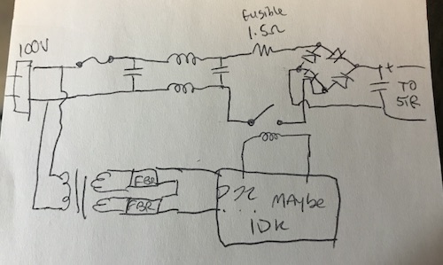
It’s gonna be the standby circuit, he told me. It’s always the standby circuit. It’s on all the time, it’s running current through it constantly, even when the set isn’t being watched. Check for a relay. This made sense to me, I told myself, and then ignored his advice.
Instead of taking the TV all the way apart and looking for the relay, I set the TV up in a precarious position and then put a multimeter on the STR3115 voltage regulator.
The STR3115 accepts DC input and pumps out 115V DC, which goes direct to the flyback transformer for all kinds of amazing high-voltage shenanigans. Why is a Japanese set using 115V internally? Beats me.
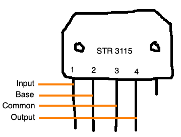
Like testing a 7805 in a Sega Genesis, I knew that there were three potential cases here:
| No power on…. | …might mean |
|---|---|
| Input pin | Standby circuit bonked |
| Base pin | ???? |
| Output pin | Dangerous high-voltage thing bonked |
Using a pair of test hook clips, so that my hands were far away from the television set while it was operating, I tested the STR3115.
Here’s what I found when measuring between:
- Input and common (pin 1, 3): 0V
- Base and common (pin 2, 3): 0V, but sometimes 0.1V
So, the 115VDC voltage regulator isn’t getting any input voltage to regulate. That seems like that could be a problem.
Now it was probably time to take CJ’s advice, like I should have in the first place. I tore the TV all the way back down to the boards, discharged the CRT again, and started my exploration. To make things easier to trace out, I used a test hook to clip one of the leads to my multimeter and then chased around the board with continuity test.
The Hunt Continues
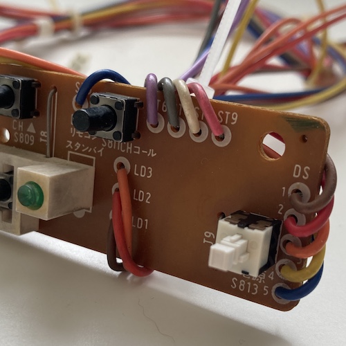
My first task was to figure out what a relay looked like on this board. I knew what an automotive relay looked like, but nothing seemed like an obvious candidate. However, near where the power cord entered the motherboard, I found an OMRON G5R-1112P 12VDC relay. It had a convenient diagram on the front to explain its pinout, but from the underside, it is hard to figure out what pin does what.
This time around, I did notice some dodgy looking solder joints on the flyback, which probably weren’t helping. I also re-checked the cracks around the STR3115 and again found that they weren’t hurting anything. Finally, I started to trace the path from the power cord, all the way through the system.
I quickly found that there were two bridge rectifiers. One of them fed a 78M05 voltage regulator near the front of the board, and the other wandered around into the same general area to power a B772 transistor, which was also wired into the connector for the power switch on the front panel.
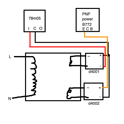
This 78m05 was the start of the +5V standby circuit, the target of CJ’s theorized ire.
While buzzing out this circuit, I found something very peculiar. The “output” and “common” pins of the 78M05 were shorted together, with 1.5Ω resistance between them. What?
Despite the hindrance of not knowing if a certain pin was ground or +5V standby, I was able to buzz out most of the control “logic.” A shrink-DIP microcontroller near the 78m05 seemed to be responsible for a lot of the TV’s functions. For instance, pin 11 seemed to ultimately be responsible for activating the system, by switching on the B772 transistor and flowing power into the relay, which itself feeds the STR3115. Yep, standby circuit alright.
Now I needed to figure out where the short was. I clamped a test hook to the output (出) pole of the 78m05 and started poking every electrolytic cap I could find on the board around the standby power/logic area. It seemed like most of the decoupling caps were ceramic disc, which, while it’s not impossible that they could short, seemed unlikely to me at the time. To my surprise, only two of the aluminum electrolytic beeped on both legs, indicating that they were across (and could potentially be involved in) the short between +5VSB and GND.
Upon further inspection, both caps had visible furry leakage on their legs and a little poop left behind on the board. I took my side cutters and clipped the leg of the smaller one to remove it from the circuit. The short to ground remained. Then, I snipped the other one out. The short to ground disappeared, and returned when I reconnected that cap to its severed leg.
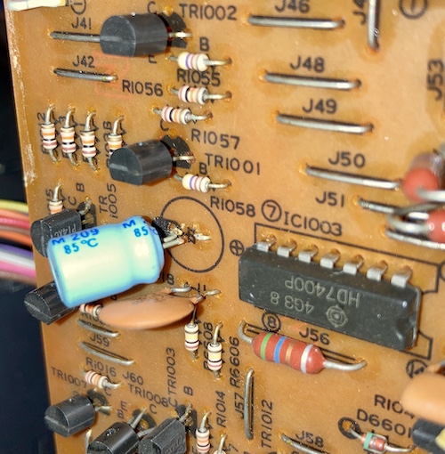
C1017, a 100µF/16V Rubycon 85°C cap with its heat shrink damaged, seemed to be the culprit of the mysterious short. I found you. Just to make sure, I tested for continuity across its legs, and found less than an ohm of resistance.
I cross-referenced it against this amazing cap list provided by tokkun01 on Twitter to make sure it was indeed a 100µF/16V cap. I am super grateful to tokkun01 for the hard work of cataloguing this television’s caps!
I banished C1017 to the land of wind and ghosts and slapped in another capacitor. I actually had many in my bin to choose from that were much smaller than the original cap, so I chose the highest temperature/hour rating. No more short on this rail after replacing both caps, so at least I fixed one thing.
CJ was right: the standby was bad. A dead short would certainly explain why it wouldn’t power up, and also the many cryptic reports from other Japanese PC-TV151 owners that the set worked great until “something went pop inside.”
I was excited, but cautious. What if this also didn’t work? I’d be crushed. Bravely, I decided to go to bed and leave it for a couple more days.
Did it work?
When I developed some more bravery, I slowly reassembled the monitor again, making sure to plug in all the squid of wiring harness connections. It’s annoying to work around the yoke board when putting the rear input board on, but I managed it again. The trick is to go from the right side of the board and work your way left, rather than going shortest-to-longest harnesses.
I plugged in the monitor and pushed the power button. I heard the vrrt of degauss and the crackle of a CRT’s high voltage coming back to life. That’s new.
Now I saw a little red light appear in the corner near the “RGB” button. Standby was working, high voltage was working, but nothing was on the screen.
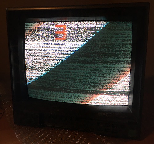
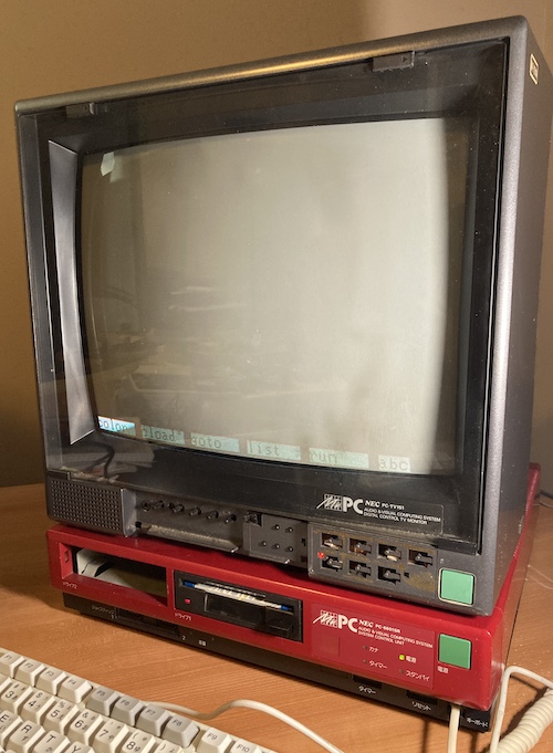
With shaking hands, I pushed the TV/Video button on the front panel. The screen filled with terrestrial TV static and the red number “3.”
I did a little idiot dance and clapped my hands in delight.
Composite Tests
I pushed the “TV/Video” button again to switch into composite video input. The screen displayed a boxy OSD (on-screen-display) “V,” and then disappeared into a blank raster6. Time to test!
And what better way to test than my Sega SG-1000 clone, the Soggy-1000? Version 3 was just lying around following its successful test, so it made a perfect testbed with its built-in Zaxxon.
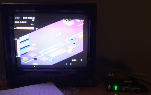
Zaxxon worked over composite video input, and the sound did too!
Unfortunately, due to the 56pF crystal setup discussed in the previous post about that clone console, the PC-TV151 had trouble finding colourburst. Eventually, it found it and rendered beautiful, vibrant colours – which didn’t get captured by the crappy backup phone I was using for the picture. There’s something else wrong, too: a flagging top-third of the screen as the TV’s hardware kept trying to compensate for this wonky sync and then adjust it back as the frame progressed.
This is the Soggy’s fault, though, and not the TV. If anything, the PC-TV151 over-performed, as a lot of modern TVs would just give up on this wacky signal while it was in this configuration. Instead, it struggled onward and produced something that a human being would still consider legible. Analogue is some tough stuff.
The next test was the MSX, another TMS9918-based system but ideally one with better colourburst timing. I dug out the Sony “HitBit” HB-101 that you’ve seen in previous articles, and connected it over composite. The output looked great, albeit with some composite fringing and purpley blues that I was able to dial out with the colour and tint adjustments.
For whatever reason, when the TV was restarted, the front panel pots would be set to effectively random values. I assume this is corrosion of a sort, and I’ll be trying to hit these with fader lube the next time the board is out. As it stands, I have to do a little bit of tinkering with brightness, vertical hold, colour, tint, etc every time I start up.
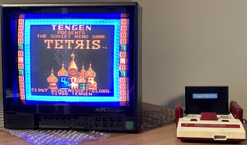
The Famicom also worked great, but something was producing a really annoying ground-loop buzz. After some confused testing, I was able to isolate it to a noisy volume control on the player two controller – aka the usual Famicom microphone noise. I wiggled the slider back and forth to scrub the contacts until the volume of the buzz died down, and was able to enjoy a few rounds of the Tengen Tetris reproduction cart I built a couple years ago.
Analogue RGB
Now that we knew composite worked, I wanted to test the JP21 RGB connector on the back. Now, while the JP21 connector looks like SCART, it isn’t pin-compatible. It’s quite a bit different, which means SCART sources will have to be adapter to work on JP21.
Unfortunately for me, I didn’t have any native JP21 output sources that I knew worked properly. Because I didn’t want to design, source connectors for, and build one myself, I ended up paying some cash to Retro Gaming Cables to get their SCART-to-JP21 adapter.
That adapter appears to be a passive fly-wired adapter inside a plastic case that’s been potted. I am a little surprised they can sell something that involves this much by-hand assembly for just £5. Maybe it’s difficult to find male PCB-mount SCART connectors?
As regular readers will attest, I am definitely not a rabid RGB adherent, so it was a little bit difficult for me to comprehensively test the analogue RGB input of the TV151. Most of my game systems are still on composite. I only have a couple SCART RGB sources, such as a supergun, a bunch of non-bypassed Model 2 Sega Genesises, and a handful of decrepit Saturns.
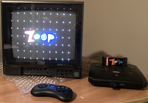
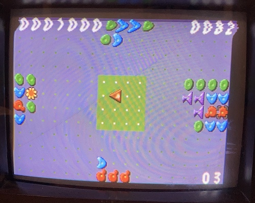
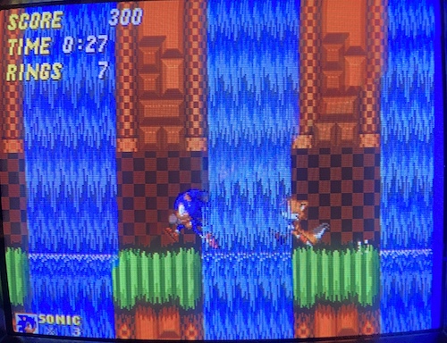
There was a lot of background noise buzz on this unmodified VA4 Genesis Model 2, as you’d expect, but the video was super sharp. Sonic 2 looks fantastic. Zoop looked great too, but exhibited some weird flagging at the top of the frame. I’m not sure if this is the AliExpress SCART cable, the Genesis, the game, or the TV at fault. Audio was very crisp.
My phone didn’t like syncing and took awful pictures with too much blue in both cases. I’ll have to remember to turn on “long exposure” mode next time.
So: analogue RGB works! That’s better than most TVs in this country. Now what about digital RGB?
Send Me A Cable
The real acid test was still to come. Will the PC-TV151 work properly with its mate, the NEC PC-6601SR? Can they combine to form the mythical “Mr.PC” of legend?
To find out, I’d need an appropriate RGB cable. On the back of the PC-TV151 is an eight-pin rectangular digital-RGB connector. You might recognize this cable as being used in some other 80s monitors and TVs, where it’s usually listed as a “VTR” cable.
Originally, the PC-6001mkII and other 15-colour models would have come with a PC-60m91 digital-RGB cable featuring this connector on the end.
In case you’re curious, NEC’s own documentation for the PC-TV151 monitor says that the monitor was compatible with these cables:
- PC-8091K (“Home TV cable7”)
- CRT adapter PC-82408 (PC-8201A CRT adapter)
- PC-CA403 (needed for “AV2” according to the documentation, appears to be a DA15-to-JP21 analogue RGB video cable for PC-8801 RGB9)
- PC-6695SR (“TV Interface Cable10,” likely the 66SR’s control cable?)
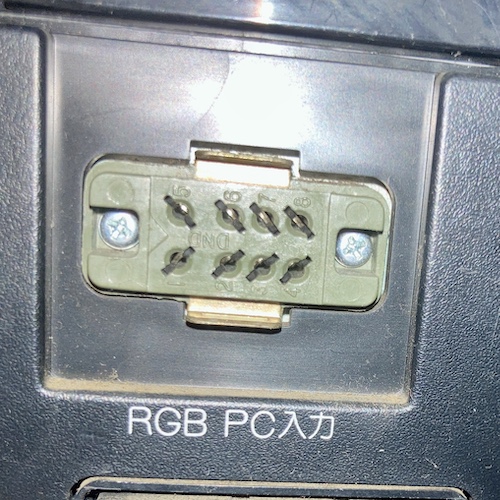
Luckily for me, the 8-pin rectangular digital RGB plug isn’t a proprietary connector, just a very obsolete one. At first, I was worried that I would have to 3D-print something. However, I did some hunting around, and it turns out that a couple vendors made the male connector that mates with the monitor. One such vendor is Hirose, whose Minicon 1300-series of rectangular connectors is documented in this Mouser datasheet.
By filling out their connector code in the datasheet, I determined that I wanted a Minicon P-1308. Lucky for me, it turns out that the 1300 series was developed in concert with NTT Co, aka Nippon Telegraph & Telephone, also known as the (at that time) state-owned telephone company. Government money means lots of surplus, lots of secondary sources, and a generally high quality part. Woohoo!!!
Being meant for telecom, the datasheet also helpfully gives a lot of cross-references, so let’s just immediately steal the relevant stuff from the Hirose datasheet:
| Hirose Part | Short Format | NTT No. | Vague description |
| P-1308-CTA | 8DLPMS | CN-1208DLPMS | Plug, vertical cable inlet |
| P-1308-CEA | 8DWPMS | CN-1208DWPMS | Plug, horizontal cable inlet (AKA right-angle) |
| P-1308-SB | 8DJMS | CN-1208DJMS | Plug, stopper bracket |
Armed with this info, I dutifully went puttering around the internet to try and find a source on any of these connectors. My hope was that using the NTT interchange number (and NTT “specification 1931,” or NTT仕様 1931) would turn up all number of salvage vendors, I could buy a connector from some disused phone-hoarding website, and quickly make my cable after burning my fingers a few times and wasting a potato.
One vendor, Casa Modular Systems, had the connector in stock but for $54.78 US dollars. However, they provided some alternative part numbers, which I’ve copied here in case that site disappears:
| Vendor | Part number |
|---|---|
| Hirose | 213-0424-0 02 |
| Short | 8DLPMS |
| Other | CN-1208DLPMS |
| Sony | 1-506-161-00 |
| TVNZ | 661-33 |
That Sony part number led me to this amazing resource about VTR connectors by “Camera Tim,” which he calls Honda connectors, because our friends at HTK were involved in making these for Big Phone too. (Everyone gets a taste!) He also notes that the Hirose 1600 series looks similar but sometimes has square pins, which won’t fit into the 1300-series female connectors.
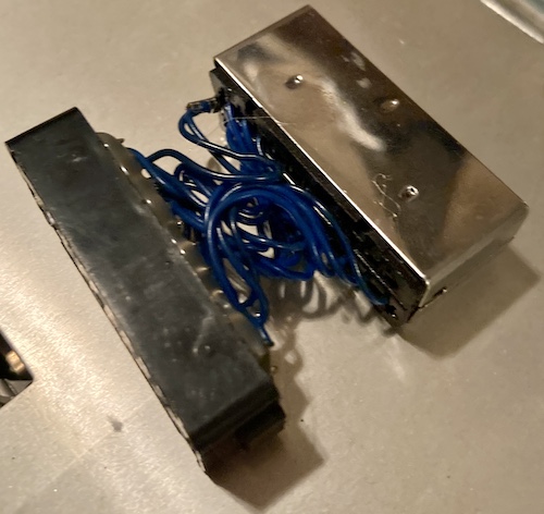
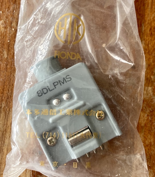
I couldn’t believe my luck when I found a lonely little Japanese electronics surplus storefront telling me they had a 8DLPMS male connector lying around and nobody seemed to want it. They have some wacky other stuff for sale, too, but I have tried hard not to look too closely, for the sake of my wallet. After telling my proxy to order it for the princely sum of ¥600 plus tax, I had what I believed to be a digital-RGB connector.
When it arrived, it was indeed an Honda Tsushin Kogyo (HTK) male 8DPLMS connector! It even came in a very cool vintage parts bag.
I banged together a quick cable from my trusty reel of CAT5e Ethernet cable, and…
At this point, I took a break to get some Invisible Glass wipes to clean the anti-glare glass on the screen with. Unfortunately, I had left the wipes out in the garage over the winter, and they had dried out after freezing and thawing multiple times. Oops. I guess you’ll have to live with whatever that greasy smudge in the corner is until I can go to the store and get some more.
Okay, let’s fire it up.
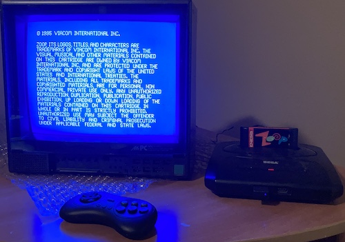
It would appear that the 66SR’s floppy drive has gotten upset and is now refusing to load the Hudson Soft Best Games Pack that it was happy to load only a few short weeks before. I removed the disk, and set the “number of floppy drives” switch on the back to zero.
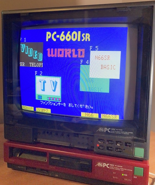
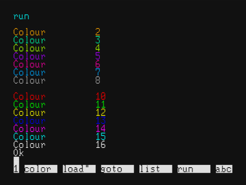
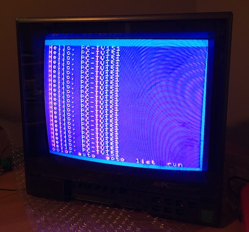
PC-6601SR WORLD is indeed showing up in 15-colour mode! You can see that all the text is crisp and has correct contrast from its background, especially the tricky “N66 BASIC” text.
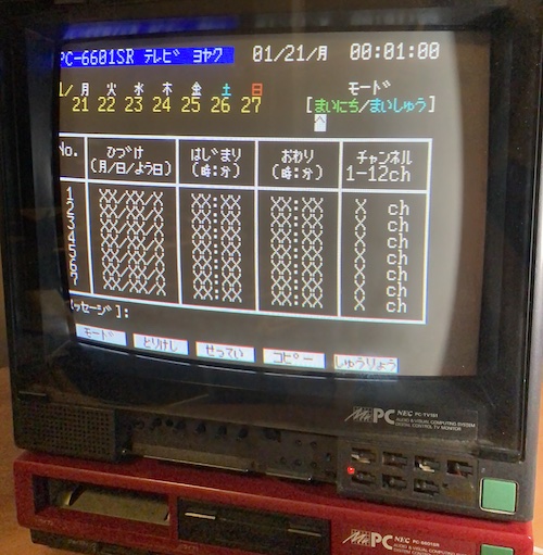
The text in the “TV Tuner” adjustment screen also looks pretty sharp. Speaking of Sharp, this sure looks a lot better than the fairly rustic TV Timer adjustment screen in the X1turbo, doesn’t it? I especially like the ritzy little colour-coded weekly calendar at the top. I don’t know much about Japanese TV standards, but it’s interesting that they only had 12 channels on terrestrial.
Unfortunately, something is up with the horizontal timing of the screen. There’s no front-panel control for this, so I soldiered on. Interestingly, starting N60 BASIC (and putting the PC-6601SR in its PC-6001mkII emulation mode) made the aspect ratio change, at which point the display was perfectly centred on the monitor.
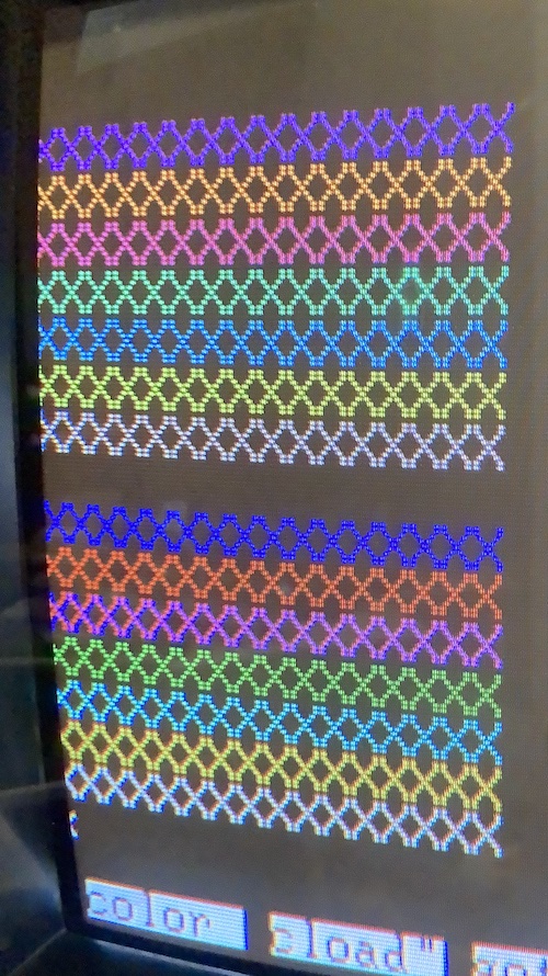
I typed a quick program to cycle through all the colours, and you can see that there is first a dim and then an intense version of each colour. It looks like I have some convergence work to do between red and blue.
Wow! I finally have 15-colour mode!!!
Just don’t ask how much it cost to get to this point.
Finishing Notes
To put the broken-off tab back onto the door, I used a bit of Tamiya model adhesive, and was careful to let it dry before I tried anything. I’d had bad luck with super glue on this kind of flexible plastic before.
That’s a good place to stop for now, I think. There’s still lots left to do.
As you do with such a complex beast that is lumbering back to life, I noticed a few mysterious things.
First, the monitor smelled like a 1980s Japanese apartment while it was running. Having stayed in a couple of those apartments while in the country, I can assure you that the smell is distinctive. Although my sense of smell is not particularly keen, I’d place it as a cross between tobacco, tatami offgassing, and musty couch stink. Putting the running monitor in a closed room with a Dyson air purifier tower fan thing during testing quickly attenuated the smell – either it was absorbed into the magic future appliance, or there just wasn’t much to burn off in the first place.
Second, the anti-glare shield is surprisingly hard to clean. After a fruitless attempt to remove the little slide clips so I could wash it in the sink, I ended up taking a new can of Invisible Glass11 wipes to the glass. It seems to have made a difference, but I can still see scuffs and baked-on gunk here and there in the corners. The clips on the front that hold on the shield won’t budge; either I’m using them wrong, or they’ve seized up somehow. More elbow grease is necessary.
Last, the geometry is a little off. The picture is tilted a bit counter-clockwise, and there’s more overscan on the right side of the picture than the left. Convergence is also not excellent. I’m not sure how this happened, considering the convergence ring clamp was tight when I was working on the tube. Maybe it’s just age, some worn-out component in the driver board, or it got jostled loose during shipping. I will probably live with this for now, because I certainly do not want to reach inside this thing while it’s running and mess with the yoke windings.
The most annoying thing is that the left side of the screen is cut off in PC-6601SR mode. But not, oddly enough, PC-6001mkII mode. This will require some further investigation to figure out just how the monitor knows these are different.
Conclusion
There’s still a lot to do with this little NEC PC-TV151, but I couldn’t be more pleased that such a big gamble has paid off. Not only is it an attractive RGB-capable CRT in its own right, but the PC-6601SR functionality finally completes one of my favourite computers.
It’s been a very educational experience and now I feel a lot more confident looking around inside a CRT. Not one that is energized, of course, but I feel like I could walk the circuit to fix a similar issue on a crappy consumer TV that I found on the side of the road.
Would I recommend importing a known-to-be-broken CRT from Japan? No, but the upsides of this risk were worth it to me in this one very narrow case. Enthusiasm causes people to do dumb things.
Of course, there is one thing that still bugs me. This is the black PC-TV151, and I have a red PC-6601SR. If only they matched a little better…
Repair Summary
| Fault | Remedy | Caveats |
|---|---|---|
| TV does not switch on. | Replace power switch. Replace shorted aluminum electrolytic capacitor C1017 on standby +5V rail. | Power switch may have been okay after all. |
-
This is a partial lie. Dim black is used as transparency for the superimpose feature. Sorry. Roll with it for now. ↩
-
NEC Home Electronics went on to do some other stuff you might have heard of: an obscure little 7.5-million-unit-selling game console called the PC Engine. Appropriately, it was also 8-bit, despite what the number in the name of the TurboGrafx-16 lied to you about. ↩
-
This explains the existence of the oddball PC-KD863G PC-Engine-in-a-monitor too – Home Electronics’ monitor can be used with either Information’s PC-9801 or Home Electronics’ PC-8801. ↩
-
In keeping with NEC corporate tradition, New Nippon Electric didn’t start out making TVs. They made radios, and some other division experimented with the new technology of TVs as they were introduced. Later, NEC corporate collapsed that responsibility into New Nippon Electric and they made TVs and radios (and refrigerators, and infrared kotatsu, and…) ↩
-
According to a post on 5ch that I can no longer find, the aspect ratio even changes. In 8-colour mode it has a PC-8001’s screen ratio, and in 15-colour mode it uses a more TV-like 4:3, like the PC-6001mkII expects. ↩
-
Because the OSD is not visible when switching to the RGB mode, I suspect that they are doing the equivalent of a cheap-and-dirty RGB mod inside this set, and pushing the RGB input into the signal path usually used for OSD. That’d be an easy way to do the superimpose, too! ↩
-
According to a block of info by “Nikon” in this 5ch thread. ↩
-
This is the same PC-8240 CRT adapter that would be used to allow a PC-8201 Kyocera 85 portable computer (think Tandy TRS-80 Model 100) to connect to a colour CRT display. As per the old-computers article on the PC-8201A ↩
-
As per this archived Yahoo Auctions page, as well as several PC-98 references ↩
-
According to PC-6001 WORLD’s photo library page ↩
-
Not sponsored, but I’d like to be. Send me free stuff. ↩