Presentcomputer 1000
Tags: computer vtech vtech-precomputer pickups mod
What if I told you that you can still buy a Z80-based computer from the 80s for only twenty bucks? It has a full keyboard, a pretty solid BASIC interpreter, and there’s even an expansion bus of sorts. And it runs off batteries!
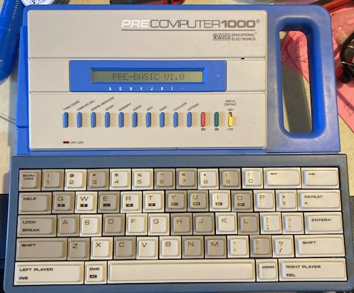
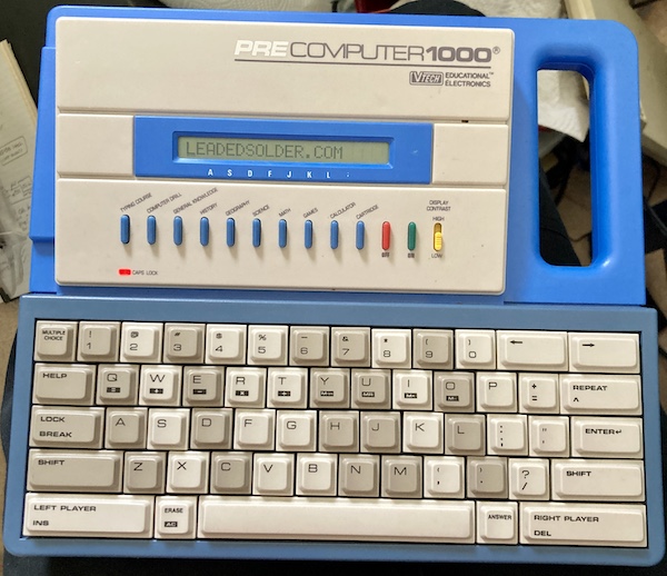
I present to you: the VTech PreComputer 1000. It was marketed for ages nine and up, although if you were nine years old in 1988, you likely already had access to a severely discounted Commodore 64 or VIC-20. Still, you can’t take those with you on a long car ride to Grandma’s.
I like buying locally whenever possible: not only is it usually a better deal than the eBay sellers who are trying to amortize eBay’s heavy listing fees, but you don’t have to pay shipping! And also something about community spirit, blah blah local economy, you know how it is. The seller of this machine was very nice, and let me do a curbside pickup and drop the money in a plastic bin on her porch.
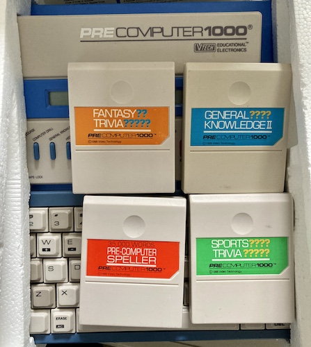
To my pleasant surprise, despite not being listed in the ad, it was boxed – and even more pleasantly surprised that it had four separately-sold cartridges in the box - none of these are the pack-in cartridge, General Knowledge, which presumably was lost somewhere along the line.
The machine is a little on the heavy side, which is no surprise as it has six C-cell batteries providing its power. There is a jack for a DC power supply too, but I didn’t get one in the box. It might have been an aftermarket accessory. I did actually like the keyboard; although it’s membrane-based, the throw is fine and I didn’t notice many missed characters. Perhaps my expectations have just been hammered into the ground by so many other terrible 80s toy-computer keyboards.
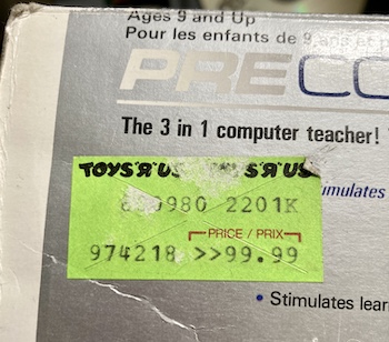
This price tag looks like it was sold originally at Toys ‘R’ Us for $99.99 Canadian. That’s not too bad of a price for 1988, considering it has a full keyboard. No doubt the toymaking expertise helps when it comes time to save money on plastic moulding and manufacture.
After looking through the rest of the lineup, I’m a little suspicious the machine is related to the slightly older (1984) VTech Laser 50. It has a lot of similar features and specs, and the slightly odd-looking DC power jack is identical.
Batteries were included (the very nice seller warned me that they were getting weak), so I decided to try and fire up the machine. After the boot screen, there is an extremely loud and shrill ice-cream-music startup song playing on the built-in piezo speaker. Oh god.
And the shrill toy music kept shrieking on every mode - open BASIC and it’s playing you a beepy little song at maximum volume. Even putting tape over the little hole for the speaker doesn’t help much, as it feels like the entire case of the machine vibrates with the sound. I decided it would be a good idea to open this up and figure out how to add a mute switch.
First, though: let’s open up the cartridge.
Cartridge Inspection
Some of that moulding cost-reduction is obvious with the cartridges. I popped open Sports Trivia to see what was going on inside. The thread-forming screws were really hard to get out because the cheap plastic had shrunken in the years since it was made, and the force of this shrinking was even starting to “bite into” the single-sided PCB inside the cartridge. It took a little prying to pop it free.
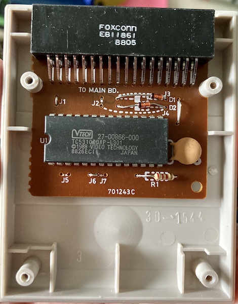
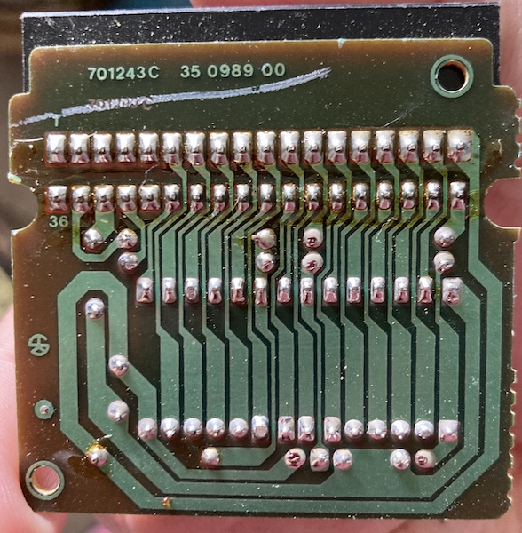
Once exposed, it all seems pretty basic: a white-labelled Toshiba TC5310001 128kB mask ROM. Cartridges have a female edge connector, because in true Sinclair-emulating fashion, the machine itself has a male one to keep costs down. The routing is comfortably straight, so it’s possible to derive the pinout just from the datasheet for the TC531000.
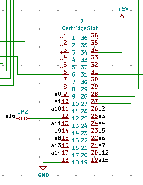
One obvious weird thing about this cartridge is that the topmost A16 line has a lot of configuration jumpers for how it’s selected. It can either be:
- Selected by the pin on the cartridge slot (J2 set);
- Pulled high (J6 set);
- Or pulled low (J7 set)
Since this particular cartridge has J6 set, the A16 line is pulled high. This seems to indicate that they must only be using the top 64kB at most of the ROM… I wonder if the lower half of this ROM is some other cartridge entirely, and they took advantage of a volume discount on burned ROMs to save money?
There’s a lot of other bank switching logic on the board that seems to be broken out to dedicated 74s (and later into the glue chip) in order to afford such large cartridges (and BIOS ROM) into the Z80’s 64kB address space. More on this in a bit.
I considered dumping the ROMs, and even designed an adapter board from the TC531000 to a 27C010 so my TL866 could do it, but it has yet to arrive – I definitely could have done it faster with a breadboard. The reason why I went to this length is that it appears that MAME’s software list is missing the Pre-Computer Speller game.
I decided to change the jumper from the J6 position to the J7 position to see if a different game would come up. It would be nice to get a little through-hole 3-pin SPDT switch for this.
When I changed the jumper on Sports Trivia, it came up as General Knowledge II! Free game! One I already own, but it’s a free bonus game! I immediately rushed to check the rest of the games.
| Game | Initial Jumper Position | Turns into… |
|---|---|---|
| Sports Trivia | J6 | General Knowledge II |
| Fantasy Trivia | J6 | General Knowledge II |
| Precomputer Speller | J2 | J2 sets A16, so this is a true 1Mbit ROM |
| General Knowledge II | J7 | Fantasy Trivia |
So there you have it. If you have a General Knowledge II cartridge, try flipping the jumper and see what else it is. Maybe you’ll get a game you don’t already own!
A word of warning: between the shrunken cartridge case plastic and the extremely soft screws, it is very easy to strip out the head of a screw. In fact, one of the ones on Precomputer Speller was already hogged out pretty badly and had to be removed with some special techniques. C’est la junk life.
When talking to another old-computer type, we came to the theory that not only is this cheaper for VTech if they made too many of “the wrong game” and had to convert an unpopular one back to General Knowledge II rather than destroy it, but it also improved yields. With two games on one ROM, you have a 50-50 chance of getting one that works if there’s any bad transistors on the mask.
Hear No Evil
Once the PreComputer is open (the outer plastic is held together with identical thread-forming Phillips screws) there are a lot of soldered wires, hot glue blobs, plastic case shavings, and ribbon cables to contend with, all owing to its cheap nature.
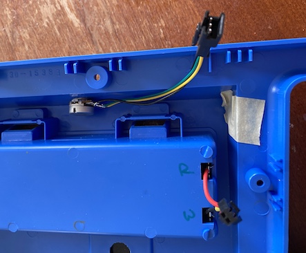
I didn’t want to pull the entire machine apart for fear of damaging the LCD, so I did what I could by unscrewing the cheap single-sided motherboard and cartridge “slot” after desoldering the battery wires.

Those wires were then replaced by some pre-crimped wires with a JST SM connector that I had originally purchased for an LED strip project. This connector will allow me to quickly disconnect the battery cleanly if I wanted to get inside this again in the future.
There’s a lot of sticky residue left behind from the disintegrating glue on the masking tape that was used by the factory to hold wires in place.
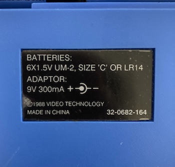
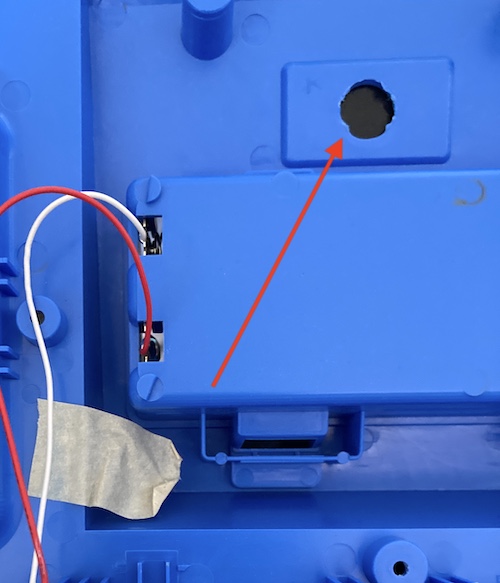
The back cover’s AC adapter polarity sticker is covering up this very crudely cut hole in the cover. I’m not sure exactly what pins this exposes, but I assume it’s for testing at the factory. This might come in handy later.
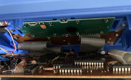
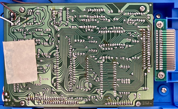
Once the single-sided motherboard was pried back, I could stick a flashlight in and read the labels off of the DIP chips. The important one is the Toshiba TMPZ84C00AP-6, a 40-pin 6MHz CMOS Z80.
If you’re interested in seeing what the front side of the board looks like, Tom Nardi at Hackaday was much braver than me and tore his completely apart to take good photos of the Precomputer 1000’s motherboard.
Decoding seems to largely be done by Philips 74-equivalent logic chips, which is kind of refreshing.
I was really hoping that the Z80’s WR pin would be directly connected to the cartridge “slot,” especially since the successor PreComputer 2000 offered a 32K RAM expansion using a backwards-compatible slot2, but it sadly appears that it is not. A real shame, as being able to read and write to the cartridge slot would open up so many cool expansion options, including coprocessors. It’s not like a clever cartridge couldn’t interpret reads to certain special addresses as commands, but it definitely deflated my motivation to keep going with the PreComputer 1000 for now.
The pins that aren’t in use by this cartridge seem to be attached to various decoder logic spread around the board (muxers/demuxers,) but I didn’t trace back any further than that. It’s possible that one of these signals is a WR by proxy, but it’s very annoying to trace this board with all the short, old, and delicate ribbon cables soldered in place.
At first, I wanted to add a “mute” switch to the machine, but I didn’t have any appropriate panel-mount toggle switches in my parts pile, and I decided I still wanted to hear the music – just quieter. A quick trip to the internet store revealed some pretty potentiometer knobs, and a 500kΩ3 audio-taper pot.
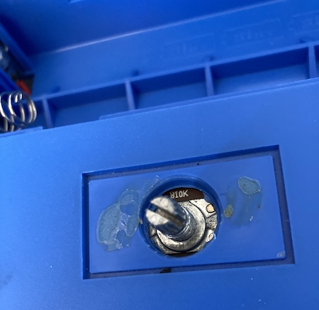
As you can see, the hole is way too big for the gland nut on the pot to hold it securely in. To provide some structural support, I ended up cutting two pieces of spare plastic sheet from the lid of a container of dish detergent packets, and drilling a 6mm hole in there for the potentiometer shaft. Once “sandwiched” around the original hole, these provided decent structural support, like using two washers. The inner recess of the “sticker hole” is 20x38mm.
If I had a 3D printer, I could have made a very clean install by making a box-shaped insert that fit into the recess, but I think I did okay with what I had to work with. The knob certainly draws the eye away from the worst of it.
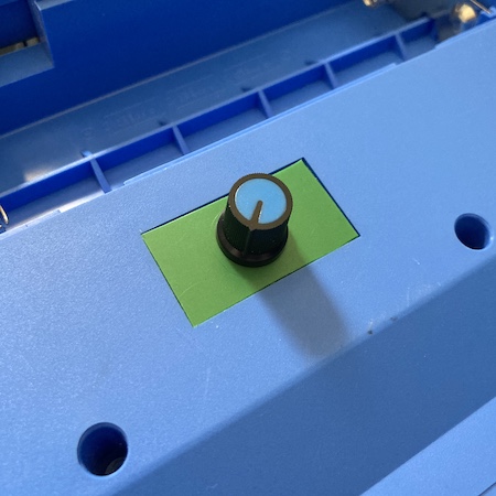
I was kinda proud of this, but then I had to throw it all away. Why? Two reasons: one, the shaft on the pot wasn’t long enough to get good thread engagement with the gland nut. And two: that’s on the underside of the computer, you know, where it sits when you’re trying to type on it. Somehow this had evaded me until I had actually done all the work.
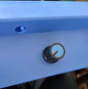
No worries: the sticker was returned to its rightful place, and then I broke out the step bit to drill a hole in the rear/top of the computer. Now, the knob would be accessible, and the computer could actually lie flat on the desk instead of balancing precariously on a potentiometer.
I ran a three pin cable (audio in, audio out, ground) from the new pot on the back and crimped it for another JST SM connector. On the other end, I tied the two speaker grounds together (old and new,) spliced into the speaker output, and then crimped it for the female side of the JST SM. Closing the case up again was a bit precarious because I left way too much wire, but ultimately it came together just right.
The volume control works flawlessly. When testing, it actually surprised me how loud the speaker actually was – I had forgotten during the couple of days that the machine was apart, waiting for the pot to arrive.
BASIC
Now that the machine is quieter, I can settle down to do some BASIC programming on the couch. There’s not much room for storing your programs (only 2kB of RAM, and not all of it belongs to you) and there appears to be no way to permanently save them (this would have been another good reason for that WR pin on the cartridge, VTech!)
The BASIC interpreter on the PreComputer isn’t terrible. It has a lot of string-handling functions, three-dimensional arrays, trigonometry functions, and it can even control that shrill internal piezo speaker with 31 notes using the SOUND command4. Even though the majority of the manual is dedicated to it, and the box hypes up the feature, VTech tries hard to hide it from the end user, tucking it away in a sub-menu of “Computer Drill.”
Postcomputer 1000
With other projects beckoning, I didn’t get to fully reverse all the decode logic on the “mystery” pins of the cartridge slot. Two-in-one games is a fun piece of mask-ROM cost-reduction trivia that I’ll have to remember for later.
This was a fun, if short, trip into an obscure little toy computer. Although I don’t think there’s much else to be done here, I’m going to hold onto it just in case some other mods or uses occur to me. You never know: one of those decoder pins could be a proxy for WR after all.
-
If this part number sounds familiar, you might be familiar with old Macs - two of these are used in the Macintosh SE for the internal ROMs. ↩
-
Bernhard Slawik has posted a scan of his PreComputer 2000 motherboard, where you can clearly see the
WRpin at position 5. He also helped quite a bit by figuring out what the extra 74 muxer/demuxer/latches were doing – bank switching, of course. ↩ -
Why 500kΩ? The Cigar Box Guitar website’s piezo wiring diagrams suggest an audio-taper (logarithmic) pot with 250-500kΩ. The 500kΩ one was cheaper. ↩
-
It tickles me that the manual literally says “Use SOUND to create tones for whatever reason.” ↩