MC-10 Hammered
Tags: computer tandy trs80-mc10 video repair pickups
Radio Shack worked hard to get their machines into every possible price tier of the home computer market, so what happened when they went super-budget? Nothing good. Thanks to hard-working community members, this unloved 6803-based computer has gone from doorstop to delight, so it’s high time that I picked one up. Of course, by law, any computer I pick up has to be at least a little broken.
Even though the TRS-80 MC-10 is called a TRS-80, it’s not a Z80. I mean, neither are the CoCos. Or the Model 100/102. Maybe their only excuse for calling them TRS-80 is because each processor has the number “80” somewhere in the name: Z80, 6809, 6803, 80c49, SC61860. Uh, maybe not that last one, but it still has “8” and “0” in it, so decide amongst yourselves.
You can think of the MC-10 as sort of a “Sinclair” version of the CoCo, designed to fight off competition at the low end of the market that, at the time, was being chewed up by the VIC-20 and the spectre of Japanese microcomputers. It’s been knocked substantially down in cost by using weaker/cheaper components, more plastic parts, only 4kB of RAM, and a crappy keyboard. The same machine was turned into the French Matra Alice, although there it has a beautiful red paint job and comes in an elaborate carrying case that justified a higher price tag.
Even though the MC-10 didn’t last long, reportedly being sold for only one year, they sure seemed to move a lot of them. It’s another one of those “doorstop” computers that is now becoming more popular because all of us old-junk addicts, having now gotten a taste for the weird stuff, are looking for a new and different fix.
Where it becomes fascinating for me is twofold:
- The 6803 CPU is a seriously limited version of the 6809 that would be challenging fun to program for;
- They still included a full MC6847 VDP1!
I picked this one up after seeing a bunch of expensive eBay auctions go by for untested machines, and I figured I might as well ask. A few hours after putting up a want-to-buy inquiry on a Discord server, I was shuffled along to a helpful fellow collector who had five of them lying around his house. Soon, the worst one of the bunch was on its way to me.
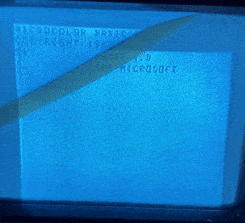
What’s wrong with it? Let’s first look at this picture the seller provided:
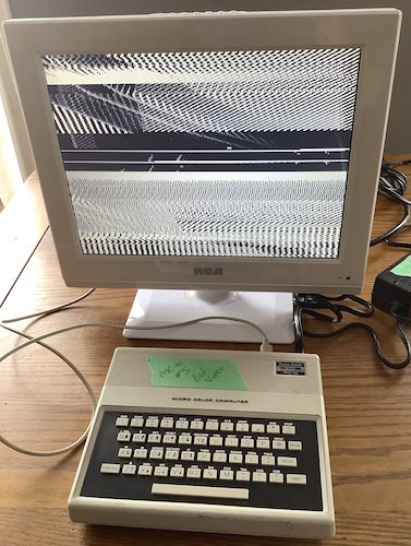
Looks like sync is screwed up, or maybe the 6847 is damaged somehow. I excitedly waited for the package to arrive.
It Arrives
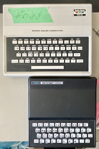
It seemed like, based on the pictures alone, that this would be a smaller machine than it is. Compared to my Timex-Sinclair 1000, a rebranded ZX81 (which also needs some work - spoiler!) the chiclet keyboard is downright luxurious. The typing feel is not spectacular, with a short throw that reminded me more of my old trusty TI-83 Plus than the full-but-spongy CoCo keyboard. I actually prefer it to the CoCo.
They both easily fit into the envelope of the Sharp X1turbo, which was sitting nearby and so became a convenient photography stand.
The Portopia Serial Port Murders
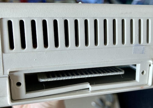
There’s a bit of damage here to the bottom lip of the expansion connector. No expansion slot cover was included, so I’m guessing someone was using the 16k RAM pack before, and gave it a good smack to crack the plastic. This should be pretty straightforward to fix.
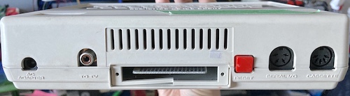
For such a little computer, they worked hard to provide at least some useful ports. You’ve got:
- An AC power jack. Yes, it needs to be AC output (see below;)
- RF out, with a channel 3/4 selector on the bottom;
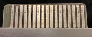
- A 34-pin edge connector for expansion;
- A reset button – an unimaginable luxury for Commodore owners;
- A CoCo-style serial port, although it’s very compromised;
- And a cassette tape connector, which the service manual surprisingly does not provide a pinout for. However, after doing some research, I determined it was the same as the CoCo and “regular” TRS-80s, just without remote motor control.
This warranty sticker – which annoyingly covers a case screw – has lasted awhile. I guess nobody wanted to mod their MC-10?
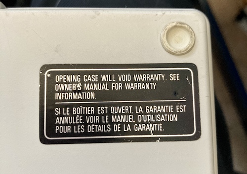
Let’s call Radio Shack to see if the warranty is still good. Nope, still donairs.
I started trying to remove this using a razor blade and hair dryer, but tore it. So I punched a hole in it with my screwdriver and removed the screw as expected.
To make up for my brutality, I decided that I would repair that nasty crack in the case. I put some Tamiya plastic cement on the plastic surrounding the crack (yes, the good, toxic kind - I learned my lesson last time) to seal it up:
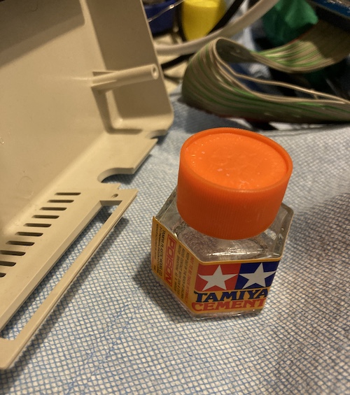
This did an okay job, but the thin plastic still flexes too much and will probably just break again at the original crack. I might get back in here and reinforce it with some wire, or build up a structural rib out of some super glue and baking soda.
Get In There
The first order of business is to get a suitable power adapter for the little computer. Reportedly, a 9VAC NES AC adapter will work just fine.
Unfortunately, despite those reports, it didn’t actually fit into the barrel jack. Either I was misinformed, or I have a special barrel jack or MC-10.
Have it your way, buddy: you’re gonna get opened up instead of turned on.
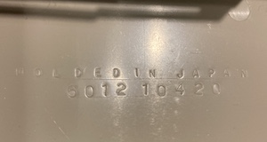
The top and bottom case plastics were moulded in Japan, but I couldn’t make out any indication of where the motherboard was made. That’s because it’s covered in a soldered-in RF shield:
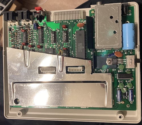
The 4700µF decoupling cap on the AC input has come loose from its glue. Between the crack in the plastic and this, I wonder if this computer has been dropped at some point in its past.
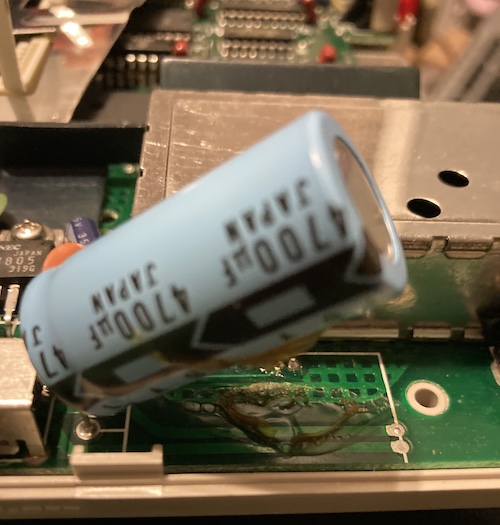
It was packed well, so perhaps being dropped is where the video problem started.
On the underside of the case are the same annoying clips that Tandy used on the Tandy 1000SX’s lower RF shield. I removed them, which took way too much time, and put everything to the side to look for bad solder joints.
Outside of some goopy flux around the hand-soldered parts of the board, and this scrape mark on the expansion edge connector, I didn’t see anything suspicious. Some large joints looked a little cold, so I reflowed them, but they weren’t in the video circuit.
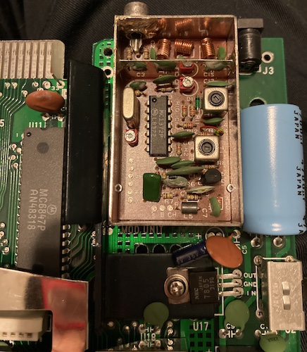
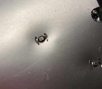
I thought at first that one of the pins of the RF modulator was shorted to ground by old flux, but after opening the can, I found out that it was the “CHAN” (Channel) input. This input is controlled by the switch on the bottom, and channel 3 is requested by pulling this pin low.
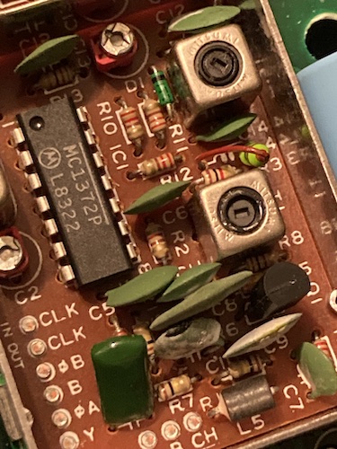
The RF can is dominated by this MC1372p, which on the CoCo is mounted to the motherboard. This isn’t as weird as the other thing present in the RF can; the 3.579MHz crystal that controls the CPU clock! Everything is running off this one crystal2.
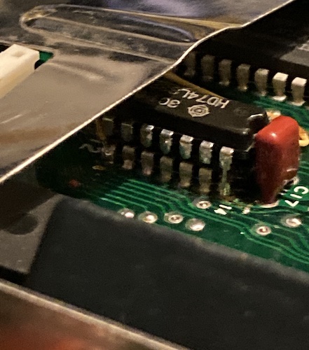
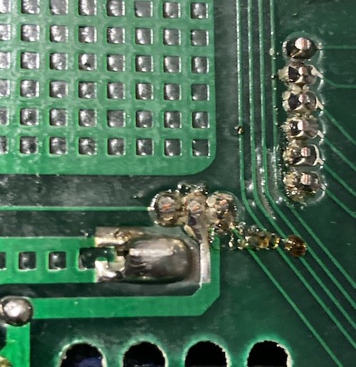
There’s also a very interesting bodge where they appear to have glued a 74LS32 OR-gate on top of another 74 series chip and then bodge-wired it in. What makes this more fun is that the RF shield has a little hump hammered into it to accommodate the extra height of the chips! It’s like a Gurney bubble for digital logic.
The Power Situation
Everything looks fairly okay inside the computer. Do we really need an AC power supply for this, or can we get away with a DC supply, like on the NES?
To answer this question, I looked at the bridge rectifier, which is a pack of diodes that serves to “chop up” the incoming alternating current in order to produce two direct current voltages - negative and positive. You’ll remember I was investigating the two bridge rectifiers of the X1turbo power supply in a previous entry.
Usually, I expect that AC input is required because they need a negative voltage; i.e. they want to rectify 9VAC into +9VDC and -9VDC, and then regulate that into +5VDC and -5VDC. That’s not quite what’s going on here. For one thing, there’s only one regulator, a 7805, which is usually used to produce +5VDC:
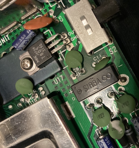
I flipped the board over a few times to figure out what was going on. It seems that the negative output of the bridge rectifier serves as the ground for the computer. The 7805 uses it as the ground when it regulates +5VDC, so you end up with feeding the logic +5VDC relative to the rectifier’s negative output. It doesn’t really matter “what” ground is, I guess, because we have a regulated +5V for the rest of the computer.
The service manual confirms my squinting:
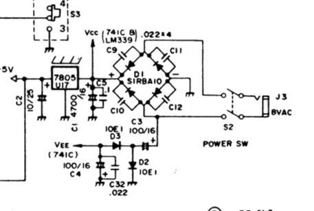
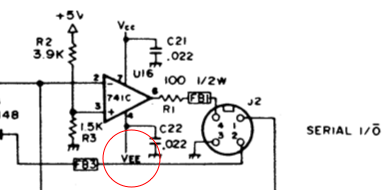
I didn’t notice the little bit at the bottom of this schematic at first. The negative side of the rectifier also feeds VEE, which is the negative voltage supply for an LM339 op-amp that’s on the serial port:
There may be other places that consume this voltage rail, but I couldn’t find them with a cursory look at the schematic. So, that’s that: the MC-10 should have an AC supply, otherwise the serial port won’t work.
How do I get my NES adapter to fit? There’s no sense in getting a whole new power adapter, especially since the only 9VAC-outputting brick on Digi-Key is $22 and has an identical 5.5x2.1mm barrel jack to the NES.
After doing some research and asking some folks, it appears that the Atari 800 (not 800XL) 9VAC power brick will fit. That’s a 5.5x2.5mm barrel, and the NES appears to be a 5.5x2.1mm barrel. Luckily, this is a common enough problem that there are some adapters floating around Amazon. I ordered a pair of 5.5x2.1mm female to 5.5x2.5mm male barrel jack adapters for $8. These fit both ends great, and soon I was dragging out my trusty Citizen portable TV (previously used to test the CoCo!) to give it a test.
Test Fire One
I turned on the MC-10 and started turning the tuning dial on the Citizen until I got a picture. And get a picture I did:
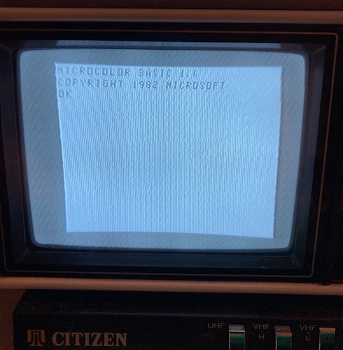
That’s a little anticlimactic.
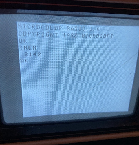
No problems with the keyboard, either, although the backspace arrangement is extremely ugly. You can either do “L.DEL” (control+Q) to wipe out the entire line, or use the left arrow (control+A) to backspace one character at a time. And there’s no left shift key! Layout problems aside, it really wasn’t that bad to type on, although I found it difficult to consistently push keys in the middle like “H” hard enough to register unless I slowed down my normal typing speed.
I waited for awhile for the MC-10’s video output to start freaking out, and when it didn’t (the 7805 and bottom of the computer got extremely warm, however) I turned it off, reinstalled the keyboard, and put the top case back on. I left the RF shield out, because it’s irritating to use, and because I suspected it might have caused a short against a solder joint when the computer was dropped. Of course, I bagged everything, so now I have a large quantity of annoying Tandy RF shield pop-its.
Disaster Strikes
After writing a few simple BASIC programs, I decided that I would check around and see if anyone was running a pirate UHF or VHF TV channel in my neighbourhood. I kept the MC-10 plugged in to the antenna input and switched on, and started channel surfing in all the TV’s supported ranges – VHF and UHF.
I found nothing, sadly, and returned to “VHF L” and started navigating back towards channel 3. Now, I found that the video was legible, but it kept rolling and flickering! Is the MC-10 video finally freaking out?
After switching to Channel 4 output and finding the same phenomenon, I was suspicious. I grabbed the CoCo quickly and tested on the same TV with the same RF adapter snake, and the video was also rolling for that computer – my test TV is the problem.
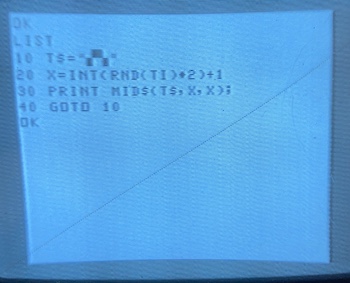
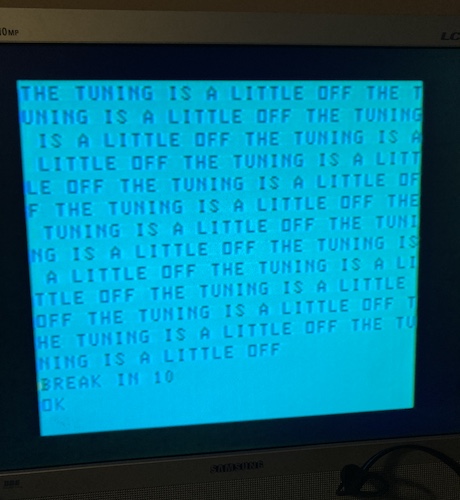
After cleaning out the “vertical hold” pot on the TV and giving it a few good taps, the vertical hold stopped rolling. I celebrated by making a little “maze” program using the character semigraphics and leaving it on for a couple minutes to see if the computer or TV was experiencing a heat-related failure:
The MC-10 seemed to be working, but when I looked at the front panel of the Citizen, something didn’t feel right. With the MC-10 set to “Channel 4,” I had to set the Citizen to almost channel 5 to get it to show up. And on “Channel 3,” I could see it dimly around channel 3 but brightly on channel 4.
To test further, I decided to get something pickier than my Citizen. Since it appeared the seller was testing on an LCD TV with a digital tuner, I went to do the same thing.
Test Fire Two
Let’s spoil ourselves and test the MC-10 with a colour TV, so we can try to replicate whatever was wrong when the seller tried it. My junk-bin Samsung 910MP was called back into action after a comfortable retirement atop an Apple IIe.
Again, since the 910MP has a digital tuner, it’s more likely to be picky about the input signal than the Citizen, which can be tuned to “between” channels if I so desired. And it seemed like that was what I had been doing in order to get the computer’s video to show up.
I plugged the 910MP into the TV (using the PAL-N adapter that the Samsung antenna jack required) and then fired it up. With the MC-10 set to channel 3, I got scrambled video almost identical to the seller’s video on channel 3. On channel 4, the MC-10 showed up:
With the MC-10 set to channel 4, I couldn’t get anything legible out of channels 3, 4, 5, or 6 on the digital tuner. Maybe when this computer was dropped, the tuner pots in the RF modulator got shaken loose and now it’s “transmitting” on a slightly wrong frequency.
Since I want to do a composite mod to this computer to make it more useful long-term, I debated doing nothing at all. However, adjusting a few little pots with a screwdriver is basically a free fix, and it was annoying me…
Tuner Culture
The first obstacle was that the two tuners in the RF modulator are apparently ferrite slugs and not “potentiometers.” It’s easy for a metal tool stuck into the coils of the slug to inadvertently become a transformer, which would make things much worse, so I bought a set of cheap ceramic adjustment tools off Amazon. I figured I would need them later for stuff like adjusting CRTs anyway.
The service manual says to try the fine adjustment on the TV, which I assume the Samsung’s impressive digital brain has already taken care of on my behalf. It then cautions me not to mess with anything unless I have a spectrum analyzer, and instead to just replace the whole RF can.
You gotta go along to get along, so I checked Kijiji to see how much a spectrum analyzer cost. The cheapest one was a gently battered Tek 2710 for seven hundred bucks, so I decided to go without.
If you have a spectrum analyzer, which I certainly do (wink, wink) the service manual tells you to do the following:
- Set channel select on the MC-10 to channel 4.
- Adjust T102 (T2 on the silkscreen) so the spectrum analyzer’s frequency counter reports 67.65MHz.
- Switch to channel 3.
- Now adjust C113 (C13 on the silkscreen) until the spectrum analyzer’s frequency counter reports 61.25MHz.
I actually have a cheapo eBay frequency counter, which I’ve used previously, but I wasn’t sure if it was the right tool for this job. I scoured the Web for awhile trying to see if anyone has done this adjustment using one, but came up empty-handed.
Ultimately, I ended up just tweaking T2 and C13 until the TV was showing the MC-10’s output. Unfortunately, since the TV is a little “smart,” the automatic fine tuning would occasionally go crazy trying to compensate for my adjustments, and I’d have to switch away from the channel and back in again to see the signal. Very frustrating. Eventually, this procedure produced workable video on channel 4 and smeary video on channel 3.
While I was working on it, the adjustable cap C13 felt loose on the board, and when I gave it some light downward or sideways pressure from the ceramic tool, it would sometimes lose the signal. I wondered if C13 might have a bad or cracked solder joint (spoiler: it didn’t) but I managed to get it to a point where the video was now reliable on my Samsung TV.
Obviously, without using the spectrum analyzer that I don’t have, the tuning isn’t perfect. It doesn’t matter long-term, however. As previously stated, my plan is to remove the RF module entirely. Something like the (unfortunately, currently sold-out) Zippster board would go a long way to making the video a lot better and the computer more usable. Maybe I’ll have to design one of my own.
Conclusion
It’s always nice to be able to bring a computer back to life. The cheap and cheerful “budget” machines are just as worthy of a little TLC.
What’s next for this computer, other than the aforementioned composite video mod? Maybe some extra RAM would be nice, or a DIY cartridge. With such a basic computer to start with, there’s a lot of places it can go.
Repair Summary
| Fault | Remedy | Caveats |
|---|---|---|
| No power supply. | Use NES AC power supply with 2.5mm adapter cable. | |
| Plastic case cracked. | Glued it together. | The repair needs reinforcement. |
| Video output bad. | Adjust channel tuning potentiometers in RF modulator to fix tuning for channel 3 and 4. |
-
Because there isn’t much video RAM, the high-rez/high-colour modes are not marked as “officially supported” in the service manual. I don’t know what this actually means for me in practice, but it could be fun to find out. ↩
-
This produces a weird wrinkle of the machine. Since the CPU is running at the NTSC colourburst frequency of 3.579MHz, this means that you can’t multiply or divide the clock frequency cleanly to achieve any normal serial baud rate. As a result, anyone who wanted to implement serial communication on this computer had to bit-bang it in software. See more on this section in the Wikipedia article ↩