Lord of the Sord
Tags: computer sord sord-m5 homemade-hardware pickups
Even after so many years of delving into Japanese 80s computers, there’s still some undiscovered frontiers waiting for me. Early on in my studies, I had heard stories about the Sord M5 and its Western VDP. Through the help of a good friend, I was able to get ahold of one, and then the first of many clone projects began.
Sord is one of those also-ran Japanese computer companies that could have been a big name. They came onto the computer scene in the early-70s and even produced a personal computer called the M200 in 1977. They enjoyed some pretty decent success and sales, and branched into the inexpensive home-computer market with the M5 in 1982. Eventually, after a series of mis-steps, an “orchestrated smear campaign” leading to the retraction of supplier credit, and the emergence of more modern competition, they were absorbed into Toshiba during the height of the bubble era.
Sord is also somewhat famous for the Sord M68, which is a beloved dual 68K/Z80 system released internationally around the same time, but I don’t have one of those on hand. And judging from the Yahoo! Auctions prices, I don’t think I’m ever going to have one, nor their later luggable, the M23. Maybe we can clone that next.
Hardware-wise, the Sord M5 has a very familiar set of specs. You’ve got a Z80, a TI TMS9918A VDP, and a TI SN76489 sound chip. Long-time readers of the blog may already be able to figure out where this is going, but I’ll spell it out: I would like to be able to make an open-source clone of the M5. I’ve already done a bunch of other TMS99xx systems, and I feel like being able to document the internals to the point where you can build a reproduction is an important part of preservation. Or at least, lowering the price of the machine, so cheap-asses like me can make their own.
A clone is somewhat held back by the M5’s party trick: a Sord-proprietary “GA015” gate array. This gate array collapses most of the discrete “74” decode logic that you would see in e.g. a ColecoVision into one chip, which makes the system much smaller, more power-efficient, and – importantly – significantly cheaper to make.
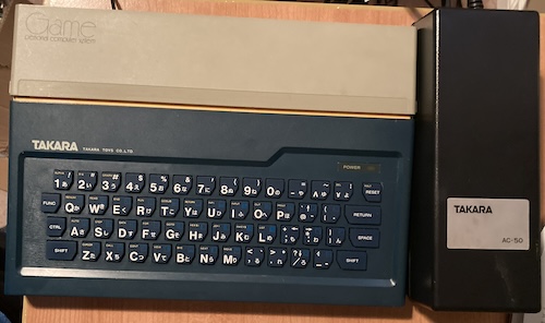
The most immediately striking part of the machine itself is just how small it is. By getting the power supply out of it and using that gate array, Sord were able to make this machine just slightly larger than a Spectrum 48k.
Thank you very much to blog superfriend bsittler for trading me this machine in exchange for some smaller e-waste. It is in fantastic shape, although it has one major flaw that we’ll get to later in the article.
One interesting wrinkle of the machine is that M5s sold under a lot of different names. This particular unit is actually a Takara1 “Game PC.”
Looking at it
Unfortunately, the M5 is cursed with one of these wobbly-disk “joypads” instead of a joystick or game pad. They are on a mini-DIN connector, which is unusual for this era, but helps contribute to the machine’s incredibly tiny size. Good thing I’m not left-handed, or this would be very uncomfortable to use.

This “attack” nomenclature on the joystick is very aggressive, Takara. What if I wanted to make a videogame about giving flowers to my magical animal friends? Maybe I’ll do that anyway. Then you’ll look super weird.
If you push the “attack” button, you will soon discover it’s even weirder than you thought. It is in fact two buttons on a sort of rocker-switch assembly. So now I have the ability to give two kinds of flowers, I guess?
Under the yellow door on the top of the Sord is the cartridge slot. It contains lots of info regarding the BASIC-I cartridge that came with the system.
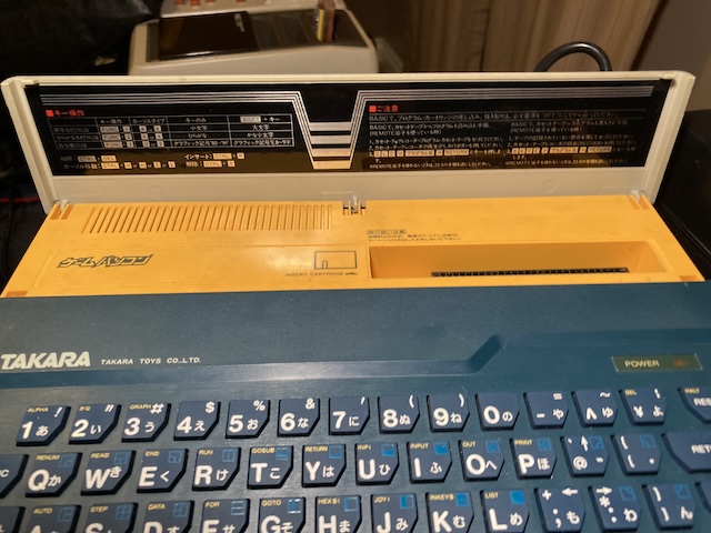
The flap is sort of a strange design choice also, as I would assume you’d have a cartridge inside the system virtually all the time. The informational stickers on the underside are helpful, but I’d much rather have a traditional cartridge-slot flap. Maybe they originally intended to have something else in the top-left area.
Of course, nothing I acquire can be perfect. This particular Sord M5 Takara GamePC has suffered some damage to its composite video output in the past, and its normal jack is missing. Instead of the right-angle through-hole soldered jack, this chunk of an RCA cable is sticking out, with a ground wire wound around it in order to artfully add visual balance as well as some limited strain relief. As much as I admire this extremely well-done bodge, I’d really prefer that it be a jack once again for the purpose of reliability, or at least consistency.
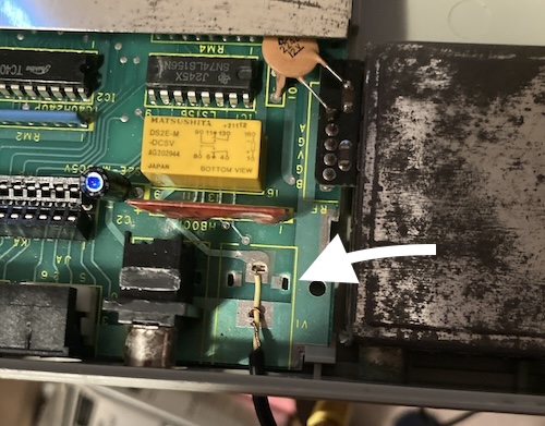
From looking at the audio jack next to it, I learned that at least the original jack must have been Hosiden brand. I have had essentially no luck sourcing out-of-production Hosiden connectors, and indeed there seemed to be nothing resembling an RCA jack on their English website in 2025. The footprint is also a tad unusual. That’s probably why this caught such a strange (yet skilful!) modification in the first place. It’s possible to see out-of-stock listings Hosiden-branded RCA jacks at various stereo supply shops, but no yellow, unshrouded ones to get a part number from. I’ll come back to this in the future.
Test Firing
Since it came from someone I knew who tested it, I plugged the thing in and started it up. Unfortunately, it didn’t start up. In fact, the power LED didn’t even turn on!
After wiggling some connectors, I started dismantling the machine. Aside from three small screws, the M5 is held together with plastic clips. The order of operations is a little complicated, but I think the correct way to do it is to remove the screws, open the cartridge slot cover, and then pry the outer sides of the case with your thumbs while wiggling until everything sort of works its own way free. It definitely wasn’t straightforward, but presented no serious obstacles.

Speaking of the RF modulator, this answered a question for me. Around the side is a mysterious switch marked as “H/L.” Opening the case reveals that the switch is part of the RF modulator. It must be for channel selection.
Once inside, I started looking around. There’s a big ol’ RF shield that dominates the machine, and it’s soldered together, but we can see some tantalizing parts sticking out of the hole. Look how much room they left under the RF modulator. I wonder if they planned to add something else here later.
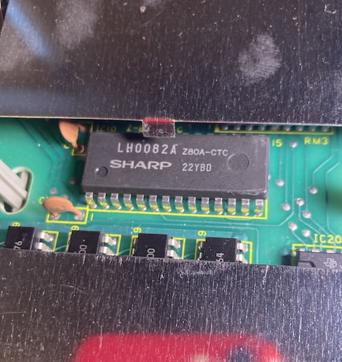
For instance, here’s a Sharp LH0082 Z80 timer. There’s also some Fujitsu MB8116 triple-voltage DRAM in order to feed the thermal-paste-smeared TI TMS9918A VDP, although not all the voltage pins are easy to reach under the shield. Rounding off the easily visible components are several HM6116 SRAMs for the Z80 – 4kB worth! – and the SN76489 sound chip.
Hidden under the shield, but still visible, is the Sord GA015 gate array. As I said up above, unlike the ColecoVision and SG-1000, this gate array absorbs all the various memory and I/O decode logic. By replacing eight or nine chips with just one, you can save a lot of money, power demand, and physical size. Based on the package, it looks like it was made by NEC, although I’m not sure what underlying gate array “blank” part number this is.
They took advantage of this to make the I/O map slightly annoying to decode, but easily memorable to a human being:
| Port range | Device |
|---|---|
| $00 – $0f | Z80 CTC (timer, interrupts) |
| $10 – $1f | TMS9918 VDP |
| $20 – $2f | SN76489 sound |
| $30 | Keyboard in, row 0 |
| $31 | Keyboard in, row 1 |
| $32 | Keyboard in, row 2 |
| $33 | Keyboard in, row 3 |
| $34 | Keyboard in, row 4 |
| $35 | Keyboard in, row 5 |
| $36 | Keyboard in, row 6 |
| $37 | Joysticks in |
| $40 – $4f | Send to printer |
| $50 – $5f | Tape I/O |
| $60 – $6f | external I/O |
| $70 – $7f | external I/O |
| $80 – $ff | Not mapped by the Sord |
The memory map is a little bit more freeform, with the monitor ROM at $0000 to $1fff , the cartridge ROMs mounted at $2000 to $5fff , RAM at $7000 to $7fff , and any cartridge RAM mounted at $8000 to the top of memory. Very generous. Overall, there’s lots of room for adding goodies! Thanks to this forum post by omikron for making it really explicit.
Anyway, back to figuring out why the M5 didn’t turn on. After finding an Aussie Arcade thread that explained the pinout of the power connector (thanks darkjedi,) I was able to probe the backside of the DIN on the motherboard. All the voltages showed up and were within reasonable bounds, so the power supply is definitely working.
At this time, I dimly remembered someone mentioning that the Sord M5 can’t turn on without a cartridge inserted2. It was bsittler, who was warning me about it before he sent me the computer, so I wouldn’t do something dumb like tearing it completely apart in a panic when it got here and didn’t work.
Checking the board again, I couldn’t easily see any part that I could identify as a BIOS ROM. Is the M5 a ROM-less machine like the SG-1000? I found a picture of the board, which clearly showed a ROM in the top-right corner. D’oh.
To make good use of this machine, I’d need a cartridge, but cartridges are expensive. Even the cheapest one I could find was going to run me nearly a hundred bucks after shipping. I could probably make something…
Let’s Make a Cartridge
The pinout for the cartridge is partially available from various sources, but I couldn’t find a really good single reference, so here’s the pinout to the best of my knowledge. I think that at least some of these pins are wrong, or at least misleadingly named, because of what happens later in this article. I will update this table with an edit when I realize what, if anything, is incorrect.
| Pin side A (solder) | Pin # | Pin side B (parts) |
|---|---|---|
| -12V3 | 1 | -12V |
| +12V3 | 2 | +12V |
| +12V3 | 3 | +12V |
| +5V3 | 4 | +5V |
| +5V3 | 5 | +5V |
| GND3 | 6 | GND |
| GND3 | 7 | GND |
| D3 | 8 | D4 |
| D2 | 9 | D5 |
| D1 | 10 | D6 |
| D0 | 11 | D7 |
| A7 | 12 | A8 |
| A6 | 13 | A9 |
| A5 | 14 | A10 |
| A4 | 15 | A11 |
| A3 | 16 | A12 |
| A2 | 17 | A13 |
| A1 | 18 | A14 |
| A0 | 19 | A15 |
| 20 | ||
| ?? | 21 | |
| ?? | 22 | |
| ?? | 23 | (cart RAM) |
| 24 | ||
| 25 | ||
| 4 | 26 | 4 |
| 27 | EX_CLK |
|
| 28 | CLK |
In most cartridges, the parts go toward the back of the system, and the solder joints face the keyboard.
A simple ROM cartridge won’t be that big of an ordeal. Initially, I wanted to create something big that would hold every version of BASIC, but I’m happy to have anything at all.
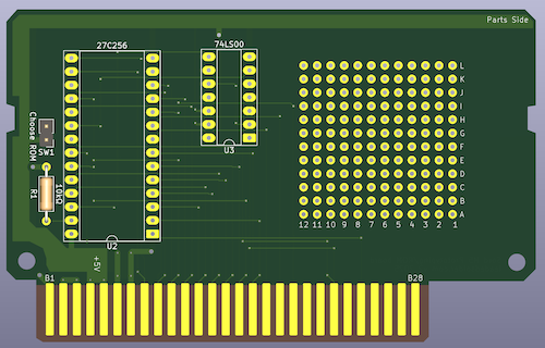
BASIC-I is the smallest BASIC available, and its ROM is a mere eight kilobytes. I decided to build a simple board that would support a 16K ROM, with an additional bank toggleable with a jumper, so that one cartridge could hold two 16K ROMs. I was sorely tempted to go whole-hog and do the entire BASIC-G implementation, with extra RAM, but I decided to hold off for now and focus on getting anything running on this little computer.
I was lucky enough to find some good-quality scans of a real BASIC-G cartridge, so I decided to try them out in the new KiCad tracing tools. KiCad has come a long way on supporting photo backgrounds for tracing. Although photos are still awkward to use in the PCB editor, KiCad is now bright enough to auto-size the image based on the DPI of the scan. With that help, I was able to just import the image, and then start tracing over it with KiCad’s tools to make an exact replica of a real BASIC-G PCB.
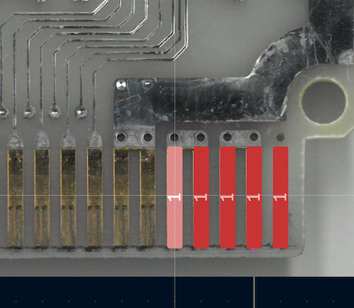
The traced board measured out to something like 102mm wide, so I shaved it back until it was 99.xx wide, in order to qualify for the “under 100mm” discounted rate at JLCPCB. It won’t be exactly accurate to a real Sord PCB, but I also don’t have a real Sord cartridge case. Funny how things like that work out sometimes.
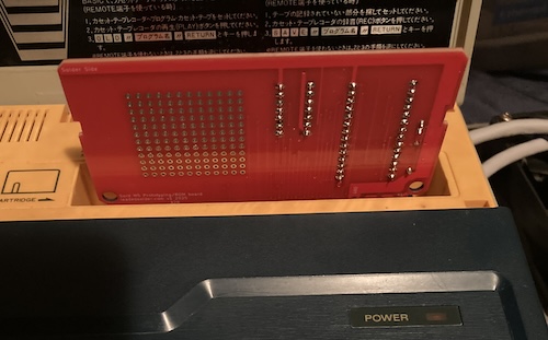
I found that it was a bit tricky to get the cartridge inserted – the cartridge slot is a little tight for a 1.6mm-thick PCB. That said, everything lined up.
Building the actual cartridge was surprisingly difficult. I had run out of both 28-pin DIP sockets for the ROM and – of all things – 74LS00 chips for the decode. I ended up using a 74HC00 and crossing my fingers. To make a ROM socket, I cut down a 32-pin socket that had a broken-off pin in one corner.
My initial late-night run consisted of a 27C256 containing two copies of BASIC-I and then two copies of Funny Mouse, each piece of software being 8K, for a total of 32K. I wanted to put on Wonder Hole, as you do, but the copy of Wonder Hole that I had was too big, at 8320 bytes, and I didn’t want to try and figure out where the additional 128 bytes were coming from this close to bedtime.
My first test run was mixed. When I flipped the switch, the power light turned on. The TV detected sync on the composite video. No smoke, which is always a plus. But… nothing happened, and the audio was the usual uninitialized-SN76489 hum that we’re all used to from other machines. What did I do wrong?
I threw the scope on it, and immediately cursed my lack of foresight in adding easy test points. The line of the ROM was cycling, but so was the synthesized A13 line, which meant that the second ROM chip select was being enabled and the 74HC00 seemed to be working
Having the second chip select being enabled on a boot didn’t make sense to me, so I temporarily cut that line, leaving it low on the ROM side, and checked again. Still no functionality, so it’s time to actually figure out what’s going on.
Let’s Lower Our Sights
I looked around for schematics of cartridges, and found this great schematic of a BASIC-G cartridge. Immediately, I noticed that is the one doing the select logic. It would seem that the select lines don’t work exactly like I expected. My best guess is that it was booting off , which mounted the ROM at $2000 , but the ROM expected to be at $4000 , where begins.
Since the BASIC-I ROM is 8K, I figured I’d be okay pulling my decode logic out and directly wiring to for now.
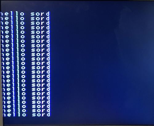
This worked! After a long, nervous delay (similar to the long TMS9918-initializing delay on the SG-1000,) I was able to see the BASIC-I sign-on banner.
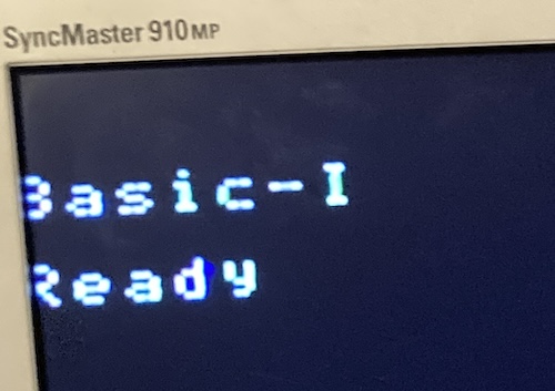
As you can see, the traditional TMS99x8 overscan issues have not been resolved on the Sord M5. Most of the leftmost column is being cut off by the edge of the set.
Of course, I immediately did what everyone must do in BASIC.
This is a very awkward keyboard to type on, with SPACE all the way to the right, and the arrow keys only accessible with a control-key command. I don’t think I would want to write anything serious on this without a keyboard adapter.
I flipped the jumper, went through another very long startup sequence, and could now play Funny Mouse. The keyboard is a lot better for game purposes, though I still found it quite awkward as the cursor keys are nearly in the centre of the layout.
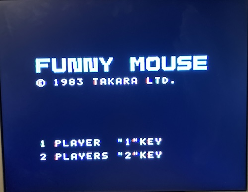
The gameplay of Funny Mouse is sort of Lode Runner-like. Without a manual, I’m not even sure that I’m playing it properly.

Inconclusion
I didn’t expect to be the pin that the ROM needed to listen to. To my understanding, that select meant that I was trying to load a ROM at $4000 , but meganekun’s Sord blog entry says (translated:)
*It is assumed that no commercially available game cartridges are executed from $04000.
And yet here I am with two commercial ROMs booting from where I think is $4000 . So either I had the wrong pinout, or misunderstood which pin did what.
When I return to this machine in the hopefully-near future, I’ll be trying to figure out the puzzle of the various select pins in order to make a 16K-capable version of this cartridge. I may simply not understand which pins do what. For instance, the schematic for BASIC-G uses to decode another 8K ROM, despite me thinking that pin only works from $6000 to $6fff – providing a window of address space much smaller than 8K!
After that, it will be clone time. Trying to work out the mysteries of the gate array, and maybe even making a clone floppy drive, will be big projects on their own. I think that a computer as cool as this should belong to everyone, though, so I hope that I can liberate its secrets in order to put yet another Z80 + TMS99xx clone system on the pile.
Thank you again to bsittler for the computer.
-
Takara was its own company until 2001, when it merged with Tomy. Any overlap in technical decisions between the Sord M5 and Tomy Pyuuta is most likely pure coincidence. ↩
-
Oddly, I found this article about how to make a ROM dumper for the M5 that tells me the machine attempts to load a tape if the cartridge is not inserted, but you need to jump the cartridge-detect pins to power it up. I’m not sure why they would have taken this feature “out,” but it’s neat that it survived to the release IPL ROM. ↩
-
Power rails must be connected properly by the cartridge PCB, or the Sord will not start. The cartridge’s presence serves as an electrical interlock to enable power to flow to the rest of the computer. ↩ ↩2 ↩3 ↩4 ↩5 ↩6 ↩7
-
See above for details on these, but is mapped from $60 to $6f , and is mapped from $70 to $7f . They are intended for cartridges to use. ↩ ↩2