PaPICOm
Tags: computer pc6001 pc60 nec p6picocart homemade-hardware
One of the hot new trends in the 8-bit computer community is the development of “Pico carts.” By using a Raspberry Pi Pico microcontroller instead of a ROM, you can make a cool software-defined cartridge that can do basically anything. For instance, it can load a ROM. I decided to make a prototype one for my beloved NEC PC-6001 series of home computer.
What is A8PicoCart?
A8PicoCart is a common ancestor of many of these designs. As you might be able to infer from the name, it’s a Pico-based cartridge for Atari 8-bit computers like the 800XL, 130XE, etc. By offering a cheap microcontroller up onto the Atari’s bus, you can not only emulate arbitrary ROMs, but also mappers and various other peripherals, just by writing some software.
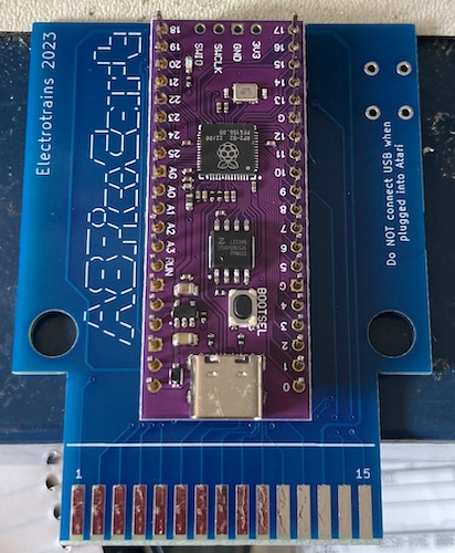
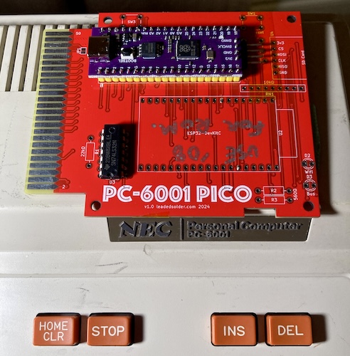
Plus, you can’t beat the small number of components. The board is basically a purple Pico clone1 and a reset button.
I threw this together and tried it on my Atari 800XL, and it worked great! You’ll have to wait for that article, though. We’re talking about a much more interesting computer today.
The basic design seems to have held out for other platforms and CPUs as well. There’s a ColecoVision version of PicoCart, as well as an Intellivision one. I’m sure there are tons of other ones out there and on the way. I thought: why not PC-6001?
Roughing it out
I had thought about how to do this for months. And during that period, I didn’t actually get anything done. One evening, I decided I would just sit down and make something, and see if it would work. Hey, a run of PCBs is only five bucks.
The FujiNet project was looking at a couple of new systems to add support for. On a FujiNet cartridge, you usually end up with some decode/buffering logic, a boot ROM, and then an ESP32 microcontroller. They were talking about changing this arrangement so that future systems would consist of a Pico and an ESP32.
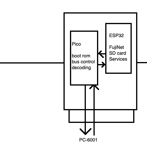
In this model, which they’re calling the “generic bus interface,” the Pico would do all the complex “platform-specific” logic, boot ROM, and timing, and the ESP32 would do all the “FujiNet” stuff. This would make firmware for the ESP32 a lot easier to develop (no more building it for six different platforms at once) and faster to add new platforms. If you wanted to support, say, the Atari 2600, you could just take the “FujiNet ESP32,” stick it down, and then implement the Atari-specific glue logic on the Pico.
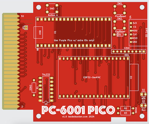
I felt like this was a reasonable design, so when I laid out the board, I also put down a footprint for an ESP32. If this worked out really well as a ROM cartridge, I could then use it to prototype the FujiNet “Pico” approach.
As I implied, the Atari 2600 and ZX Spectrum are the guinea pig platforms for this design. I mostly copied the ESP32 pinout from the FujiNet Atari 2600 build, and then used my best/worst judgment to lay out the Pico.
My first design was very simple: I ran all 16 address lines and all 8 data lines directly to the Pico. Then I put the and lines behind an OR-gate (wait for it…) to tell the Pico when the PC-6001 was trying to read the ROM off the cartridge.
Unfortunately, this meant I ran out of I/O pins on the Pico very quickly. Even using the purple “Ultimate” Pico clone boards, I still only had 30 I/Os, and I was using up 24 of those just on address and data pins! I would not have enough pins to do RAM or I/O decoding. But I had enough to do a ROM emulator, which is good enough for a prototype. Remember, I was trying to get something working, rather than make it perfect.
For the firmware, I decided I would simply copy whatever A8PicoCart was doing to offer up ROM. Surely, it was something fancy involving the Pico’s PIO accelerator, right?
Studying the A8 PicoCart code
Finally, I decided to just look at the source code for the A8PicoCart cartridge’s firmware. Within only a few minutes of tracing the code, I realized there was nothing fancy going on at all. The Pico, it turns out, is fast enough that you can serve up a ROM from a standard C program.
By default, the A8PicoCart starts in a “menu” ROM that’s stored in the Pico’s flash and loaded into memory at startup.
That program does basically this:
- Wait for the (chip select) pin2 to be asserted, indicating the Atari wants to read a ROM on the cartridge.
- Grab the requested address off the bus, and use it to look into a ROM stored in the Pico’s memory.
- Put the byte stored at that address on the data bus.
- When deasserts (the Atari is no longer reading the ROM,) stop driving the data bus and return to step 1.
When you make a selection from the menu ROM, the ROM instructs the Atari to make certain special commands to the Pico cartridge by writing to a memory-mapped port on the cartridge. That port’s commands are interpreted to do Pico-side things like “change game.” Very simple design, and it seems to work very well.
This is not to say that the C program is written naively – they take heavy advantage of the RP2040’s “GPIO masks” feature, which lets you change pin directions and read/write them in bulk. That means that working with GPIO pins is much faster than the old ATMega chips in the Arduinos, especially if you are used to using some of the slower wrappers in the Arduino library to read pins one at a time.
Now that I knew how the ROM-serving scheme generally worked, I made a copy of the A8PicoCart code, and I started hacking it up to work with the cartridge I had just built for the PC-6001.
Getting a first response
Writing code is easy. Writing working code? I’ll let you know when I’ve done it. This time was no different – my initial version of the code didn’t even show up reliably at $4000 and couldn’t be run as a cartridge. Using PEEK(&h4000) in a loop in BASIC, I would get random numbers back. Most of the time, it would be 126 ($7e ) but other times it would be 255 ($ff ,) like it was an open bus with no cartridge at all.
As you do, I made a couple half-hearted tweaks to various things to see if it magically started working, but no success that first night. Or the second night: even if I was returning a ROM image of all zeroes, it was not changing what I was able to peek at the cartridge’s location in the memory map.
If I inverted the “listening to” pin, , it was able to hang the PC-6001 and keep it from starting up. So at least I knew that the cartridge was driving the data bus. Finally, I put the thing on the scope like I should have, and realized that was never being fired.
After some more fiddling, I determined that I had made an extremely basic mistake. I wanted the chip select to fire when either or were active. They’re active-low signals, so I want something that puts out low when either one is low.
| A | B | Output |
|---|---|---|
| L | L | L |
| H | L | L |
| L | H | L |
| H | H | H |
Unfortunately, I thought “or” and then went for a 74LS32, which is exactly the opposite of what I wanted, because I’m dealing with negative logic:
| A | B | Output |
|---|---|---|
| L | L | L |
| H | L | H |
| L | H | H |
| H | H | H |
Essentially, I had converted it into an “and.” Because the two chip selects are never enabled by the PC-6001 at the same time, this logic would never enable the Pico to start chunking out the ROM.
To fix this, I cut the output trace off the 74LS32, and then wired it directly to the pin. I used because I knew the PC-6001 wouldn’t try to automatically boot off a ROM mounted there, so I could inspect the contents using BASIC rather than just repeatedly crashing.
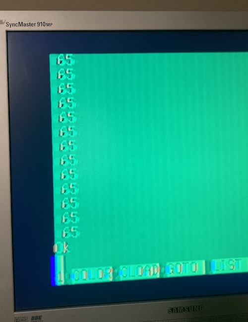
As expected, the Pico was correctly selected at $6000 , and asking PEEK(&h6000) returned the dummy value (65) which I had rigged the Pico’s program to do.
It’s working!! I quickly rushed to make it decode the address pins and then return the contents of the rom array, but the PC-6001 refused to boot the ROM. Some more investigation was needed.
Trying to figure out why it won’t boot
When the Pico notices the chip select has been triggered, the next phase of operation is to read the address pins off the bus. This address tells us where the PC-6001 is trying to look into memory. We can quickly convert this address into one relative to our ROM in memory, and then, in theory, return rom[address - start_of_cartridge] back to the PC-6001.
Initially, I had done a fairly complex mask-and-shift operation to get the address off the GPIO pins quickly. To make sure it wasn’t my math, I quickly changed the decode logic to simply return rom[address % 8192]. 8K is plenty for Hello World.
This now worked, and let me get the first two bytes of the ROM, which is the boot signature “AB.” In other words, I was able to see 65 and 66 when I read $6000 and $6001 from the PC-6001, respectively.
The next part of the ROM is the actual code. I tried an EXEC &h6002 to jump right to that code, but something was going wrong from there. I suddenly remembered that my Z80 Hello World program was using absolute addresses instead of relative ones, and therefore it would expect to be mounted at $4000 , aka .
I quickly moved the bodge wire from the previous section to the input pin, and…
Now it boots
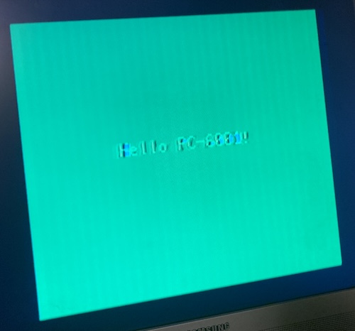
This let my 46-byte Hello PC-6001 program boot. I just loaded an entire ROM off of the Pico! That’s so cool. Just one of the cores in this $6 Pico clone is powerful enough, that I didn’t even have to use the PIO accelerator to make it respond in time to the Z80’s memory request: just a straight C while loop, and not a particularly well-tuned one either (I’m doing modulo in the middle of it!)
Amazing.
Advanced bootage
I decided that a menu system would have to wait until I wired up the pin. Although it is certainly feasible to do many mapper-like things with just pure reads to tactical addresses (see most Atari 2600 multi-carts and mapper-carts,) I figured it was better for my sanity to focus my attention on trying to load just one game. There are more musings on this particular problem down below.
As we’ve already established, on the PC-6001, cartridges are given two easy decode pins to listen to, which are triggered when there is a read to a given memory range:
| Signal | Memory range |
|---|---|
| $4000 – $5fff | |
| $6000 – $7fff |
Because these are only 8K apertures, I would need to listen to both of them in order to load a 16K ROM.
Remember up above where I planned to configure the pin to listen for either or . But I didn’t know which one was being triggered in this design, because I didn’t connect . Without that extra bit of knowledge, my firmware has no idea if the system is requesting the upper or lower section of ROM, and I don’t have any GPIOs left to listen to it.
Or… I didn’t. Since this board is basically being thrown away when version 2 arrives, I decided to repurpose some of the GPIOs that were supposed to be used for the Pico to talk to the ESP32. Implementing the ESP32 right now would be premature, and simply not populating that second microcontroller gives the Pico back easily enough GPIOs to implement RAM-and-friends… and the select pin.
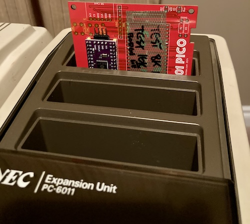
So I did a bit of firmware fiddling, and a lot of jumper wire action, to wire up the select line to an unused ESP32 communication pin. This produced a very spaghetti-laden cart that I hoped could load the 16K Canyon Climber ROM.
After an evening of tweaking of the bitwise math to make sure I entered into the main ROM emulation function whenever either of the CS lines went low (instead of both,) I was able to once again see my old friend Hello World. It’s incredible how much time you spend in this hobby just to get back to the state you were already at.
Now for a more challenging effort: Canyon Climber. That’s a 16K game that doesn’t need any extra RAM, which should test if I’m able to boot a 16K ROM.
After another evening of jiggery-pokery with bitwise math, I was able to make the Pico determine the difference between and , and correctly return to the host computer different 8K chunks of the ROM.

This meant my selects were working, but once I put in the Canyon Climber ROM, I started to have bizarre crashes. I ended up tinkering with that some more, removing that modulo I had added for paranoid reasons, and got it to run after a few more evenings of head-scratching and hair-pulling.
Because I debugged it over some late nights, I still feel a little uneasy about this code, so I will be revisiting it once I’m in a better headspace to actually think about things.
Look at that! A 16K ROM, served from a freakin’ microcontroller.
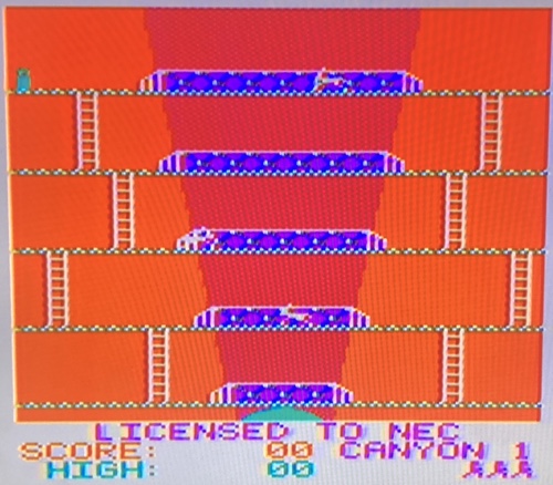
That’s pretty awesome!
Thank you for your heroism in the face of surgery, chunk of silicon.
Future ideas
Having a software-defined cartridge is super cool. Not only am I better at writing C than FPGA equations, but it’s cheap, too!
Here’s some of the ideas I’ve had for this cartridge, down the line when I have more GPIOs available and more brain cells to write and debug embedded code. Note that I’m not promising anything, but hopefully this should give you an idea of what kinds of crazy stuff this kind of cartridge can eventually get up to:
Wireless network connectivity using FujiNet. You’ll notice that an ESP32 footprint is already present on this board. It’s mostly here to reserve the physical space for it in the future, so I don’t get sloppy and pack this thing full of logic or SRAM like a nimrod and then have to rip the entire board apart later to make room for the ESP32.
Like I said up above, members of the FujiNet project have been engaging in a “generic bus interface” research project, where machine-specific Pico firmware will be used as glue logic to let an ESP32 running identical-across-platforms “server” code interact with the computer. This is one of the prototypes in this research.
I’d love to be able to play Five Card Stud or download new games off the internet. And it’d be great for rapid development, too!
SD card loading of ROMs. Like most microcontrollers, the Pico can easily talk to SPI peripherals, and it’s a super quick job using off-the-shelf libraries to get it reading an SD card that’s been formatted in FAT. I figured out how to do it in about an hour on a different project.
We could put a multicart menu up at boot time, load ROMs off the SD card into the Pico’s memory, and serve them just like the “Hello, World” ROM. Imagine having every single PC-6001 cartridge ROM (there aren’t many, although I reserve the right to make more) on one cartridge! We could even emulate complex mappers like the Warrior cartridge.
SD card loading of floppy images. On a stock PC-6001, floppy drives attach through the PC-6011 expander unit, which is – you guessed it – a cartridge. We could put Extended BASIC on this ROM, and emulate the I/O port that Extended BASIC uses to talk to the floppy drive (very similar to the PC-8001 floppy drive.) There are not many disk images floating around for the original model PC-6001, sure, but wouldn’t you like to save your BASIC programs to a SD card emulating a floppy disk, instead of tape?
SD card loading of tape images. Most PC-6001 software was distributed on tape, not ROM cartridge. If we can somehow hook tape reading (perhaps by patching the stock BIOS and disabling the original BIOS by asserting the pin) we could serve up P6, CAS, and P6T tape images from RAM as well.
Freezer. A freezer cartridge like ISEPIC pauses the CPU’s execution to do things like patch code (cheats,) or dump memory (cracking copy protection.) If we can control the Z80’s line accurately, we could even be able to rip loaded tape games right out of memory as snapshots, and load them back in later. A lot of cool peripherals are available to do this on the Spectrum and C64, so why should we be any different?
Accelerator. The Pico’s got two ARM cores. We’re just using one. Those cores are fast enough to emulate an entire PC-6001 on their own! Imagine what superpowers we could give the PC-6001’s poky little Z80 with several hundred megahertz of modern microcontroller. Esubi’s FPGA-based P6 Nanocart already does crazy things like serve up video playback to the machine.
Sound emulation. Blog superfriend polpo has made a card called the PicoGUS. You might have heard of it; it lets you play classic IBM PC games while (very accurately) emulating an array of 80s sound cards that now cost as much as a Volkswagen. There’s not a lot of games on the P6 that use FM audio, but I’m sure an enterprising someone could figure out a similar cool thing to do with an emulated Sound Blaster or SN76489.
There’s tons of other cool things that a cartridge could do. All you have to do is write some C!
Am I going to write that C? Well, uh…
Take in a movie at the Multiplex
As we determined earlier, this particular cartridge is very limited by not being able to write to it. Without write, or pins, the utility of this cartridge is limited to ROM emulation.
I do have a simple scheme in mind to modify this cartridge in order to provide 16K RAM, but I haven’t gotten around to testing that yet, and it will mean dropping the ESP32 from the board to free up pins anyway. I simply ran out of GPIOs otherwise. If I manage to get 16K RAM and a ROM on the v1 board, I will absolutely be bragging about that in a future entry.
There is, of course, another development in the wings.
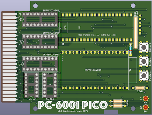
In version two of this board (pictured above,) I plan to multiplex the address and data buses. “Multiplex” is a very fancy word to use to say I’m going to make them take turns.
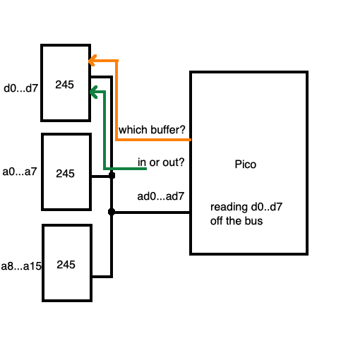
I’m only going to use 8 GPIO pins at a time, and decide whether I’m currently looking at “data pins,” “address pins (lower,)” or “address pins (upper.)” Saving 16 GPIOs is going to make a huge difference, leaving lots of room to add pins like and RAM decodes.
The only downside is that it takes extra time to construct the address from this, and to switch the buffers around. I simply don’t know yet if it will take too much time, and cause problems with the PC-6001’s bus cycle. In the end, I may have to end up using one of those fancy PIO accelerators after all!
Power off
Although there were lots of snags along the way, I’m really happy with how this worked out. The idea that a cheap microcontroller is fast enough to emulate the ROM in an old 8-bit computer is amazing. We can put anything we want in that ROM – the potential is huge.
Thanks for reading!
-
The “purple” Pico clones, or the “Ultimate RP2040,” as they’re often called on AliExpress, are Pico dev boards that are configured in such a way to expose all the available GPIOs of the Pico. The standard board only exposes some. To compound this issue, the PIO accelerator needs contiguous pins, and the standard board steals some from the middle of the range, instead of the end. I haven’t bothered to figure out why they picked these specific indices. ↩
-
It’s a bit more complicated than this because of the 6502’s Phi2 and other various additional Atari-specific pins, but the gist is that the ROM is eventually selected in some way, just like on a real cartridge. ↩