TI-83 Plus One More
Tags: computer calculator texas-instruments ti83-plus lcd repair
Although it may not be considered an “old” computer, a TI-83+ from the futuristic year of 1999 has a lot of appeal. It’s got a Z80, it runs a BASIC interpreter with machine-language program support, and lots of fun homemade games were built for it over the years. There’s also the small matter of me wanting a desk calculator with which to do binary/hex conversions, so I picked up this broken one to attempt to nurse it back to health. Will my efforts add up to a working calculator?
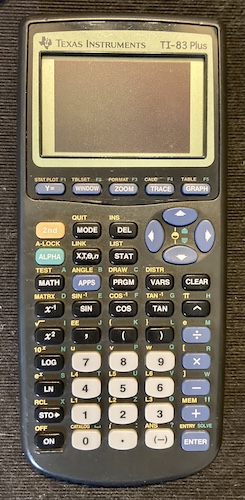
I first attempted powering it on. As advertised, I got the black screen. The brightness controls didn’t work, so I guess it’s not going to be that simple. I soon found, however, that I could push 2nd + ON to turn the calculator off, which means that the CPU and ROM are alive, and the calculator is listening to its keyboard. This is likely to just be a display fault.
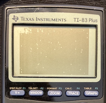
Removing the CR1616 backup battery – which still reported a solid 3.0V on the multimeter, good work Panasonic – and reinstalling it made little difference, except now I could tweak the screen brightness and enter characters. However, nothing was legible and the display just kept getting progressively more screwed up.
Opening the case took a fairly long T6 Torx driver. Then I worked my case spudger around the edges, which popped three clips loose. Once the back is removed, it revealed this surprisingly wrinkly-looking cardboard RF shield. Did this thing get wet?
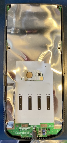
Two small Philips screws come off to get the RF shield off.
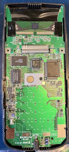
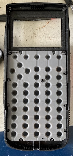
As you can see, there’s not really much going on inside this big tall case except for the keyboard. There’s SRAM and a flash ROM, and what appears to be a big custom glue chip and gate array that probably implements all of the actual system1. Everything else, including the power supply, is scattered around the edges of the keyboard and battery compartment.
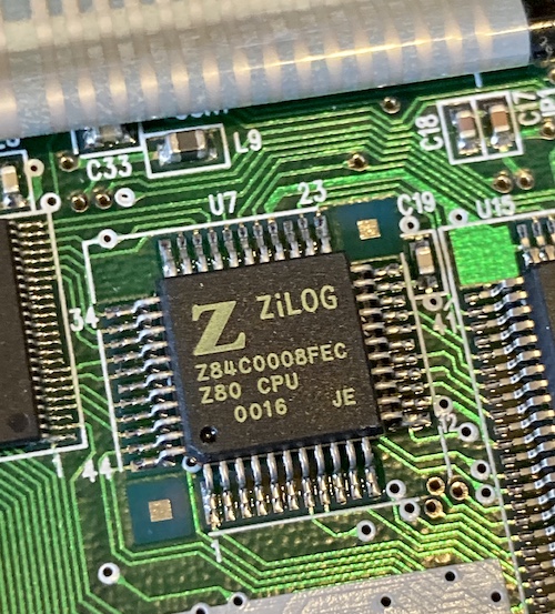
Here’s our friend, a Z80! This is of course a very small surface-mount CMOS variety, a 44-pin Z84C0008 which is rated to run at 8MHz (it appears to run at 6MHz.) There isn’t anything else on the board that’s obviously damaged, although the surface-mount capacitors near the opening for the backup battery are very sticky to the touch. Another point in favour of “something got spilled in here.”
On the other side of the case, the keypad has one single, very big membrane keyboard. It feels pretty good despite this, and the membrane contacts are very clean.
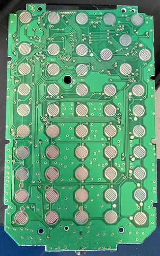
It’s a little weird how many vias are on this board. They don’t seem to be integral to the keypad matrix, but they might be stitched into the pours in order to provide additional cooling or noise reduction.
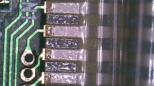
North of the Z80, we see a ribbon cable going to the LCD. There are surprisingly few pins going to the LCD board, and I reflexively buzzed them out to make sure they were continuous. Almost half of them (eight out of seventeen) didn’t seem to work! Could it just be that the glue holding the ribbon cable to the pads has deteriorated, or the cable itself got damaged by whatever was spilled inside?
Cable For Mr. Instrument
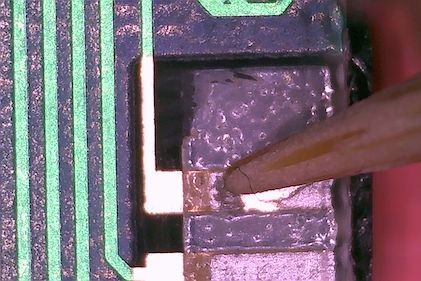
I suspected that you could repair the conductive glue on the ribbon cable in the same way that some Game Boy LCD repairs are done. By rubbing a soldering iron tip over it, you’ll heat-cycle the glue and apply some extra pressure to make good contact again. It didn’t feel like a solid solution to me, and since both sides of this connection have fairly generously-sized solder points… why not just solder some wires?
Steeling myself, I cut the ribbon with a pair of scissors and then tried to peel it all off the board, but a thin layer of glue stayed behind after the plastic was gone. I tried a few techniques to peel this glue off, but ultimately ended up using a toothpick to scratch the glue away from the pads. The wood of the toothpick is soft enough not to damage the pad plating, but is big enough and coarse enough to be a good scraper.
Go Ahead And Jump (Jump!)
I started the laborious process of cutting off 17 jumper wires, and stripping the ends. At first, I skipped tinning them, but that produced some crappy joints and I ended up having to redo those anyway.
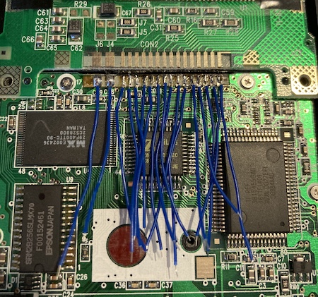
After about 30 minutes of tennis-elbow-inducing wiring, I had the motherboard side done. Then I used a screwdriver to bend the wires into a gentle curve, so they wouldn’t get kinked.
Occasionally a wire would get crossed over and I’d get confused which one I was working with, because they’re all the same colour. Were I to do this again, I would suggest picking two colours of wire, and alternating them, in order to reduce this risk, and also make it look prettier.
Some of the joints were difficult to make because, even after multiple rounds of cleaning with alcohol, they still had fragments of glue in the adjoining “not-pad” region that got melted and pulled in. I’m not enormously proud of this soldering job, but it is physically strong and none of the joints were dull and cold in the end.
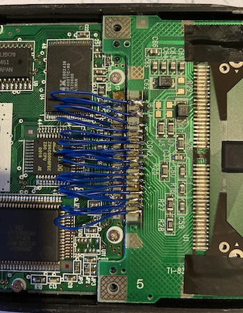
In retrospect, I probably should have used thicker-gauge wire for the power and ground pins. Their pads are much larger, and I’m guessing the LCD has a decent current draw. There’s a bit of “ringing” in the LCD that I don’t remember being there when I was last using one of these, but it’s possible that nostalgia has made my memory faulty.
30 more minutes of soldering onto the LCD panel, and it was finally done. I slapped some Kapton tape onto the LCD-side joints for safety, and then put the back case on and installed some batteries. Is it working?
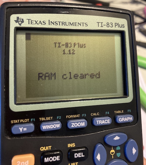
This screen is always shown on startup after a loss of battery-backup power; the internal contents of the calculator’s RAM are scrambled and must be reformatted on the first start. After this, it worked as normal: I was able to write a BASIC program and do some simple math.
Annoyingly, unlike the TI89 Titanium I had been using previously but put aside due to its voracious appetite for AAA batteries, I couldn’t figure out how to easily do a base conversion with the built-in BIOS ROM. I ended up writing a small BASIC program to do decimal to binary and binary to decimal, but it’s annoying to switch between that and calculator mode for things like bit flips and simple math, and I’ll have to track down or make a serial cable to get a nicer one.
Let’s Talk About Ethics
Having opened the 83+, I now understood that it must have cost virtually nothing to construct. There are only a couple inexpensive ICs, and one of them is a proprietary TI gate array that can most likely be fabricated cheaply. Over the course of several decades, they must have been making a large integer multiple of the build cost in pure margin while not updating the product.
This wouldn’t be so bad if not for TI’s pressure campaign to be the mandated calculator for a lot of high school math classes and standardized testing. Asking a bunch of rich suburbanite kids to spend $150-180 Canadian on a TI-84 Plus is one thing, but I’m not sure I could really sleep at night forcing a disadvantaged family to pay that much for a machine – multiple days of work at even a $15 minimum wage – that surely didn’t cost more than $20 to construct. TI’s effective monopoly power hurts these kids as much as it has chilled the development of better graphing calculators with superior feature sets from other manufacturers.
While a lot of other devices featured on this blog are just toys or luxury goods, this one is an essential tool for kids that is sold at predatory markups.
Conclusion
Even though I think it entered into my life originally because of an abuse of monopoly power, it’s a nice mini-nostalgia trip to have a TI-83+ again. I think in the future it would be fun to write some more Z80 programs for it, and maybe even do something ridiculous with it like television output.
I wonder if anyone’s disassembled the ROM to add commands yet?
Repair Summary
| Fault | Remedy | Caveats |
|---|---|---|
| Screen displays all-black, or garbage. | Replace LCD ribbon cable |