Can't keep The Most Useless MSX down
Tags: computer casio pv7 msx keyboard corrosion repair
Even after I got it to boot by replacing the video chip, the Casio PV-7 MSX1 still had a bunch of problems. Top of mind were the broken keyboard and the corroded power jack. Let’s fix these issues too, so we can get back to enjoying this el-cheapo computer and the free programs on offer in the manual.

Don’t Go Snooping Around In Dad’s Hosiden
First up is the rusty power jack. Here’s a blurry picture of what it looked like at the end of the previous entry:
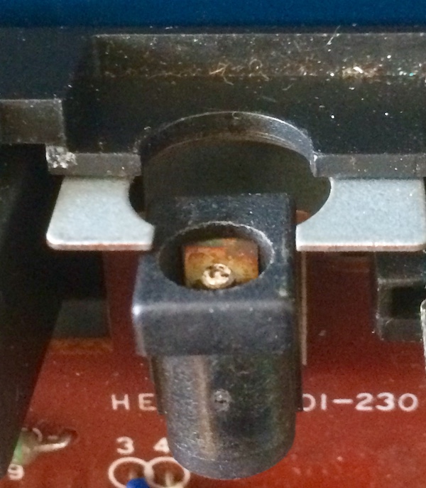
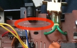
Figuring out what the power jack is was pretty simple. The part number (HEC0470-01-230) is literally silkscreened onto the board. I just looked at the photos in the previous entry from when I took it apart:
This resolves to a Hosiden part, although it’s a pretty generic DC power jack. I did a few searches to see if I could find an exact replacement, perhaps some new-old-stock, but I didn’t get any luckier than being able to find a bit from the catalogue with the exact dimensions we’d need for replacement.
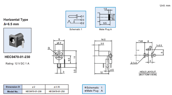
It seems I need a 6.5x2.0mm jack for a like-for-like replacement, which isn’t uncommon but not something I had on hand. All of the DC jacks in my bin were 5.5x2.5 or 5.5x2.0mm like the Genesis (and Leako) expect.
I could spend some effort hunting down an exact replacement, but the original Casio linear power brick is fairly old, feels cheap, and is meant for Japanese 100V. Although it just goes into a 7805 regulator anyway, so the extra little bit of voltage from being plugged into Canadian wall voltage just turns into heat, there was a golden opportunity here to just swap out the jack entirely and use another adapter.
After a little bit of tedious catalogue/datasheet work (there has to be an easier way) and doing a bunch of scrap-paper scribbling to match “bottom views” from one datasheet against “top views” in another, I ended up with the CUI PJ-002A, which is a 5.5x2.1mm jack. You can’t throw a rock without hitting a 5.5x2.1mm 9-12V DC centre-negative wall-wart – for example, the Sega Genesis Model 1’s MK-1602 adapter, so this held a lot of promise for me as an interchange.
The replacement was a fast job. It took me much more time to get the plastic clips on the case undone than it did to desolder and swap the jacks.
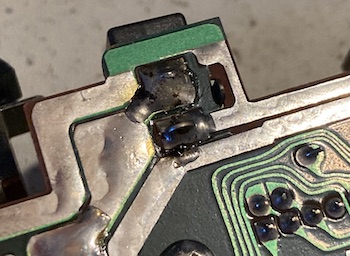
The old power jack had some globby-looking solder and suspiciously large holes in the PCB, so I’m guessing this has been reflowed to fix some broken solder joints in the past.
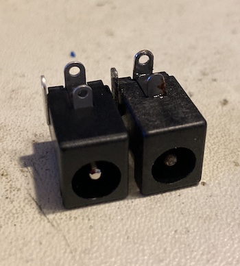
New versus old.. the old one was very rusty. I’m amazed it worked at all, now that I’ve seen it up close like this.
With the new jack installed, I connected it to the Sega MK-1602 DC power adapter that seems to have almost permanent residence in my power strip, and fired it up. Works great!
Unfortunately, the new jack seems to move around a lot on plugging and unplugging, which might eventually crack the solder joints or even rip the pad on the motherboard. I tried adding even more solder to serve as reinforcement, but I think ultimately this needs some other form of strain relief, like epoxy. For now, though, it works – and works well. No more worries about gently bumping the system and losing power in the middle of a game.
Key-bored
Are you as sick of keyboard repairs as I am? Damn things are usually so fiddly, but at least on this one we have “no keyboard,” instead of “some keyboard” like on the CoCo1. That means that the failure has to be something pretty dramatic instead of a bunch of little subtle neglects. Sometimes that’s easier, or at least more obvious.
When I posted the previous entry, I got a quick tip on the keyboard failure from another MSX enthusiast, Daniel Padilla, who reported that his Casio MX-10 MSX1 had the same problem and the cause was the conductive material having sloughed off the thin ribbon cable connecting the keyboard membrane to the motherboard. I took a look at my PV-7’s ribbon cable to see if I had the same damage:
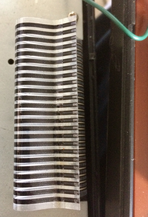
That definitely looks to be the same damage.
Daniel fixed his MX-10 by shortening the cable to expose ‘new’ contacts, in the same way that Sinclair enthusiasts trim their ribbon cables down on the ZX81 when that keyboard membrane starts to go bad.
A repair video by a Japanese enthusiast, Kojikoji, shows that the keyboard ribbon problem also affects the later PV-16 model, which seems to use the exact same parts. Kojikoji cleans the keyboard membrane’s contact points with flux cleaner, and fixes broken solder joints on the floppy motherboard connector.
I decided to try a bit of copper conductive tape. This was a really annoying process consisting of cutting them precisely to width and then trying to align them on all 24 pins. I got much faster near the end, but not any more accurate, as you can see.
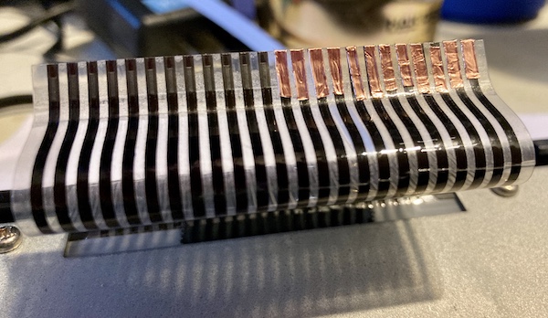
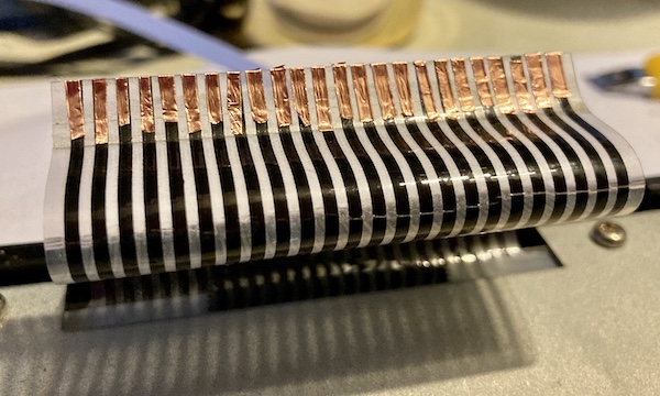
I put a little bit of Kapton tape on the top to make sure that they wouldn’t fray when they were inserted into the ribbon connector on the motherboard, and then slotted it in. It all connected very well and looked great, but the keyboard still didn’t work. None of the keys did anything.
It seems I had jumped the gun. When I took the ribbon back out (being very careful not to tear off the new tape) and did a continuity test from some exposed carbon contact to the copper ribbon, I didn’t get continuity. For whatever reason, the conductive adhesive on the back of the new copper tape didn’t seem to actually be continuous with the carbon tracks of the ribbon… what a waste of time!
I tried a few more desperate tricks here and there (pushing down on the tape really hard, heating up the tape with a heat gun set to extremely low temperature to reflow the adhesive) but ultimately it seemed like the composition of the PV-7 ribbon might not be the same as on the CoCo keyboard.
Before breaking out the resistive paint (i.e. Electric Paint) and redrawing the tracks, a messy job I didn’t relish, I decided to take a trip to the keyboard connector. It felt kinda wiggly.
How’s The Ribbon Work, Anyway?
I took a look at the female FFC connector on the motherboard. Maybe I could at least verify if the problem was only on the keyboard membrane side, or if there was something wrong with the motherboard as well.
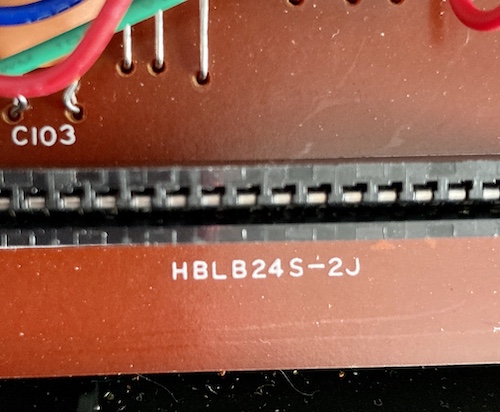
The motherboard-side connector is an HBLB24S-2J with a 2.54mm (0.1”) pitch. I wish every manufacturer would put the entire part number on their silkscreen like Casio does! I was tempted to buy a replacement in case the pins had gotten saggy, but it just wasn’t in the cards. You may find it surprising that there aren’t many flat-flex connectors made for a pin pitch this wide in this day and age.
I decided to take a power squint at the underside of the keyboard membrane while I was at it. Maybe it was all rotten?
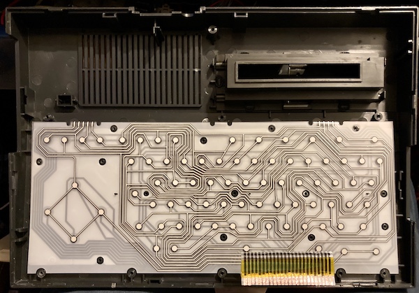
In the meantime, I decided to take a look at the keyboard membrane itself, to see if it had any obvious damage. It looked fine - almost factory fresh except for some dust - and when I test-pressed a handful of the keys while looking from the underside, there were no obvious breaks in the lines. This wouldn’t explain why no keys work; if I had internal membrane damage it would be much more likely to manifest like the CoCo’s keyboard did, where some keys work but not all.
The keyboard has an interesting design; it’s got rubber squishy domes on top of the membrane but under independent plastic keys. If they spent all that effort to mould the keys, why didn’t they just put conductive pads and a thin PCB behind them like a Commodore 64? But I digress.
As stated previously, I noticed that the keyboard connector felt a little wiggly. I’d seen other people reflow the joints on their PV-7s, but the joints on mine looked fine. A little cold, sure, but nothing dramatically cracked. A quick reflow later, and then I went to test again without changing anything else.
I pushed a couple of keys, and letters appeared on the screen! It was true that you had to use a lot of force with this keyboard, and not all the keys worked, but we were getting somewhere.
After some more experimentation, I worked out which keys did not seem to be working at all, no matter how hard I pushed.
Enter The Matrix
One of the more helpful aspects about the MSX standard in this situation is that the keyboard matrix is defined right in the standards document. Here it is, copied from the MSX Technical Data Book:
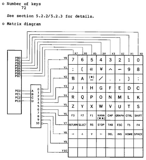
PB0..PB7 and PC0..PC3 are pins on an Intel 8255 peripheral controller. The i8255 does a lot of heavy lifting in an MSX, including handling memory pages (“slots”) and reading the keyboard. A lot of MSXes collapsed its function into a big custom chip to minimize parts cost and balance-of-trade deficits with big American microprocessor monopolies, and the PV-7 is no different. Its “i8255” is a Fujitsu MB64H131 gate array.
Here’s the keys that didn’t seem to be working:
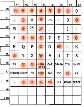
That’s not reassuring, except that at least I was making progress now.
There’s no particular pattern here, unfortunately, except that column X4 is definitely blown out. It connects to PB4 of the i8255, but that pin is not known on the Fujitsu gate array, which doesn’t help me use it to figure out which pin on the keyboard ribbon that is.
The Magical, Self-Fixing MSX Keyboard
After I took a break and came back to do a little more testing, it became obvious that some of the dead keys were working, but not all of them. I had to push the other keys unbelievably hard or multiple times, but they “came back” with more cycling. I was only missing all of column X4 after this run - you know, 4, W, G, O, [, left arrow, select, and kana after this run. The rest of the keys weren’t pleasant to use with all this force, but they were finally showing up for work.
For some reason, I decided that I would snap the machine back together after tightening the screws on the keyboard membrane retaining plate, and see if the structure of the case would help things. This had the opposite effect, and the keyboard “lost” a lot more keys again. It came back apart, and I reseated the cable. Again, it wasn’t great. I went to go do something else for a few days, and came back to it again.
This time, everything worked! Some keys (especially the first “column” of Q, A, Z, etc) were not very responsive, sure, but they all worked. I wonder if it was just a matter of exercising the keys enough to clean some corrosion off the membrane, as a few more tests in subsequent days showed that it was still working just fine.
I cleaned a couple cartridge games that had come in since the PV-7 was first taken apart, and loaded them up. The d-pad on the case worked fine (as well as it can) except that the left arrow wasn’t working. However, everything played great with a joystick plugged in, so it may just be dirt inside the membrane or trapped under the d-pad.
I quickly lost motivation to fix that one key, and moved on to playing some Door Door.
Conclusion
This is a vast improvement over the useless lump this poor computer was before, but I still don’t really trust the bizarre keyboard. There is almost certainly a better way to do this than the conductive tape, but now it is a functional (if very low-memory) MSX1 that can work on easily-available power supplies in the North American market and be used to write BASIC programs.
At this point, I’m sorely tempted to sell the machine on to someone else who will give it the finishing touches, but… maybe it could do with a RAM upgrade first.
Repair Summary
| Fault | Remedy | Caveats |
|---|---|---|
| Corroded DC power jack | Replace power jack with new part | |
| No keyboard response | Put copper foil tape on the eroded keyboard membrane “tails.” | May have been better to use a silver conductive pen. |
| Partial keyboard response | Exercise the keyboard a lot to remove corrosion from the membrane(???) | How long will this last? |