Look, mom! X1's on TV!
Tags: computer sharp sharp-x1-turbo repair capacitors
One of the coolest selling points of the Sharp X1turbo is the built-in “telopper” board. With this board, you can superimpose computer graphics on live TV, and smear dithered-colour games across my tiny Sony CRT. Guess which of the two I’m planning on using it for?
The original problem with the telopper board is that this board had a short somewhere on the 12V rail. And not a mild short, either - the resistance between +12V and GND on the telopper board was only 1.3Ω.
This short freaked the power supply out, and to prevent damage to other vital components downstream or to its power transistors, it shut itself off. All of these things happened so fast that, to the ordinary human being selling the X1turbo back in Japan, it seemed like it just wouldn’t turn on.
By unplugging the +12V power connector from the telopper board, the X1turbo was able to power on and function. But I didn’t feel good about this - if there was any unpowered logic being driven, it could cause sporadic faults in the future, or even damage it. The best thing to do is to isolate the short, fix it, and try to determine what might have caused the problem and what else it damaged.
A Short Trip
There’s not much on the +12V rail of the telopper. It took me longer to take the case apart than to trace out all the parts attached, and that’s not really bragging. Taking this machine apart involves lots of fine-thread screws, tricky connectors and holes in old rusty metal that really should be chased. Even with all the practice I’ve had taking apart and reassembling this machine, it still feels clunky every time.
At first, I suspected the two tantalum capacitors on the telopper board. They shorted on the PC-6001, so why wouldn’t they short here? Well, for starters, neither of them were on the +12V rail. Instead, there were some electrolytics. I hadn’t encountered shorted electrolytics before, but, not finding anything, I decided to arbitrarily try removing and testing one.
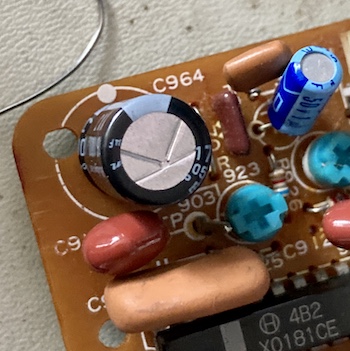
As soon as I removed C964 (16V/1000µF) from the circuit, the short disappeared! And testing the legs of C964 with my multimeter (after discharging it, of course) I got the shrill/delightful beep of a continuity test. It’s better to be lucky than good.
For kicks, I tried testing the cap with my ESR meter. You might expect a shorted cap to have low ESR, and it in fact did.
I had a replacement cap on hand, so I put it gingerly into the board and then slammed the board back into the X1turbo.
I pushed the power button, and heard the fans spin up. The computer was up and running, now with the telopper plugged in. A followup check with the multimeter showed +12.18V, so it wasn’t even getting browned out by any near-shorts. I’d fixed it!
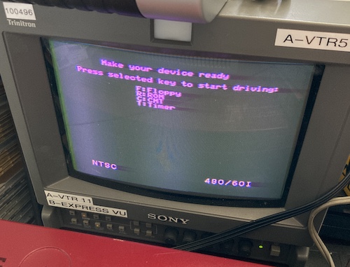
Satisfied, I decided to test the telopper’s function. I wanted to see if the “video output” was working:
It sure wasn’t! If you do the old scrambled cable-TV squint, it looks kind of like this might be white-on-black text from the X1’s IPL startup screen, but the PVM is complaining about losing sync, and the picture wasn’t even close to timed properly. I let this run for a few minutes to see if it would magically get better, but when it didn’t, I pulled the telopper board back out of the computer.
The Next Steps
Figuring that whatever whacked C964 probably took out the other caps on the rail as well, I replaced all the other electrolytics in the +12V circuit.
This didn’t make any kind of a difference, so I went to town on the remainder as well. Nothing was obviously wrong, except two of the 47µF caps had leaking bungs and the ESR tester couldn’t even detect them being connected.
I pulled part of a pad when I was removing two of the 1µF video-filter caps, but I was able to patch wire both of them. The pads are very thin on this kind of single-layer board, so impatiently rocking or trying to pull a cap out that’s still held in with a little bit of solder is a terrible idea. Better to snip the legs, but even that adds a bit of risk from having to rock the cap in order to fit the cutter blades under the body.
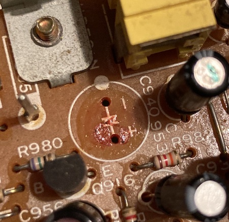
C940, the 470µF output filter capacitor, had some weird red stuff underneath it. This wasn’t leaked electrolyte, and the cap tested out okay. Maybe some kind of glue.
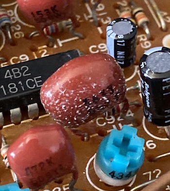
I also saw this weird furry gunk on one of the caps. None of the other caps of this type had the same gunk on it, and it wiped away with alcohol, but I wonder what it was. Mould?
Captain PVM
Once I got the entire cap job done (at least 25 caps!) I was able to put it back in the machine and test it. The output looked virtually the same, except maybe now there was a little bit less “flagging” on the right side of the image.
I was disappointed by this outcome, and started thinking about what other component might be the problem. The furry capacitor, perhaps?
Then, I thought a little harder: the PVM was getting sync sometimes, and the output did look a little bit like white text on black background that changed with the progress of the IPL. What if the Sharp was just cranking out a resolution that the PVM didn’t like?
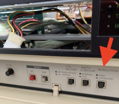
Remembering my episode with the PC-8801mkII, I checked the front panel. There, I found a “resolution” toggle button, which was set to HIGH. I toggled it to LOW and restarted the machine.
Telopper is fixed! Was it broken in the first place, outside of the shorted cap? Who can say?
I would have a cool picture of compositing together the X1’s output and the TV input, except I can’t seem to figure out how to do it yet. My best guess is that I need to render a “chroma key” colour onto the X1’s framebuffer in order to tell the telopper where to put the incoming video. It definitely makes a huge squid of cables on my desk, so maybe it will have to wait until the X1 keyboard adapter prototype is smaller than a brick!
To make it up to you, and since the computer was already open, I decided to do some maintenance…
My Biggest Fan
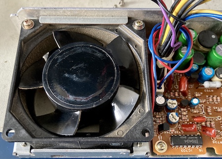
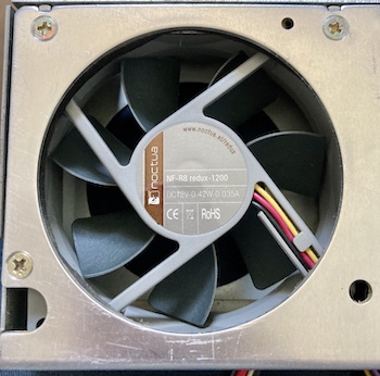
One of the things that I found annoying about the X1turbo is the rickety old cooling fan in its power supply. It had a whittering noise and couldn’t keep a constant speed, both of which were indicative of a dry bearing. Additionally, it was clogged with nasty dust that I wasn’t able to easily move even with a toothbrush. To solve this problem, I went in my parts bin and dug up the 80mm Noctua Redux fan (NF-A8, non-PWM) that I had originally purchased for the Tandy 1000SX. And then I took the entire computer apart, again, to get the power supply out.
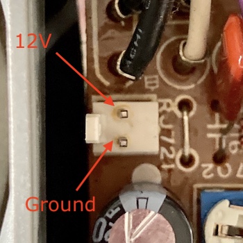
Because the original fan had red and blue wires instead of the red and black a sane person would use, I wasn’t sure exactly what the pinout was. To determine which pin on the PSU’s fan header was +12V, and which one was ground, I did a continuity test between the pins and the case.
The original fan is 1W, and this one is only about half that. It bolted right in, although the plastic shroud was a bit shallower than the old one, so I applied some washers to make sure it was securely mounted.
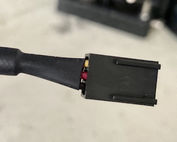
Since it’s a newer fan, it has a 3-pin connector for speed sense (fans that are speed-controlled through PWM will have one more than that, for a total of 4.) Because the X1’s power supply’s fan connector is only 2-pin – +12VDC and ground – I depinned the original connector and clipped the yellow tachometer wire off. Most Noctua fans I’ve bought in the past came with a small collection of adapter harnesses, but not this one, I guess.
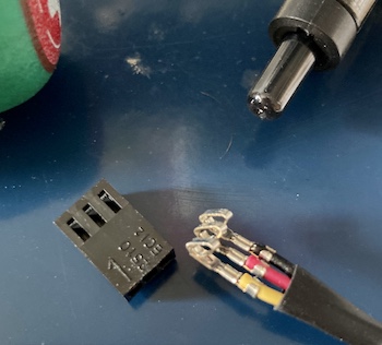
None of the 2-pin shrouds I had on hand matched the crimps, so I made a quick order for a replacement part that would fit. I picked a Molex 0022013027 shroud, which fit the original crimp pins perfectly, and fit the male connector on the PSU well. The retention tang on the male side was bent a little bit back because the “teeth” on the tang didn’t perfectly line up with the “ramp” on the shroud (I probably should have bought just the “rib” version instead of the “ramp/rib” version) but the fit was tight enough that it wasn’t going to come loose any time soon.
To test and see if the mounting arrangement would rattle or if I got the pinout wrong, I hooked the fan up to my bench power supply with 12V, and it happily pushed lots and lots of cool air with almost no distinguishable sound1. This thing is quiet. I guess that’s why it cost twelve bucks.
One other difficulty is that the cable on the Noctua fan is much longer. I dealt with this by wrapping the excess length around the main wiring harness. The original fan also did this with two loops around the harness, but I added a few extra coils, and then zip-tied them tightly together so that the case could close.
It closed just fine. The fan is a little bit more futuristic looking than the old one, but you won’t be able to see it through the fan grille on the side of the case. After a few minutes of putting bracing back on and weaving cables through it, I was ready to test – and it tested just fine.
The new fan is so quiet that I have to pay very close attention to the machine now to make sure it is actually powered up. On the first startup, I thought that it wasn’t turning on, and had to hold my hand over the fan opening to feel the breeze. It’s so quiet that now I notice a little bit of a crackle from the internal speaker on startup, which may be dried-out amplifier caps, or might just be how this system always was, but the crackle was inaudible over the din of the cooling system before.
This Noctua fan was definitely an upgrade that was worth the money, and I think I’ll do it on more computers in the future. My mkIISR has an especially audible fan – even though it’s in good condition, it is absolutely in the “model helicopter” range of volume.
Conclusion
It feels good to be working on the X1turbo again, and also to resolve the previous repair’s lingering doubt about driving unpowered logic. With a little more work on the disk drives and keyboard adapter, I think this could become a very nice little computer and maybe even a permanent resident of my desk.
Repair Summary
| Fault | Remedy | Caveats |
|---|---|---|
| Short on +12V on telopper | Remove and replace shorted electrolytic cap C964 | |
| Video output on telopper scrambled | Set front panel resolution switch to “normal” instead of “high” | |
| Fan is noisy and choppy | Buy a new fan |
-
I also tested the old fan in this way, to make sure that it actually was making a groaning sound and wasn’t just being throttled by a dying 12V rail on the original power supply. It ran just as choppily, noisily, and poorly on a straight 12V power supply, but only drew 0.05A, which at 12V is 0.6W, much less than the claimed 1W. Strange! ↩