It's All Above Single-Board
Tags: computer sbc6809e pickups
When you get a gift, the best thing to do is to put it on your pile of projects for several months, and then slowly assemble it over the course of a year. That gift, of course, is an Office Tetsu MC6809E-based single board computer. It was given to me by blog superfriend CDP, who had ordered a set of them and surely wasn’t going to build five.
What is the SBC6809E?
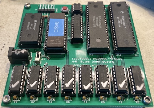
Simply put, this is a single-board computer running the Motorola 6809 CPU. That’s the same CPU as in the Tandy CoCo, Dragon 64, Fujitsu FM-7, and a bunch of other computers.
At least with the included ROM, it runs Microsoft Extended BASIC. It’s not clear if that BASIC was made from the Dragon 64 sources for the 16K BASIC.
In order to provide interactive use, the SBC6809E communicates with a terminal over serial.
Sourcing Parts
Because there are quite a few vintage components used on this computer, finding all the parts was tricky. It’s not quite like my own clones, which are mostly 74-series logic with only a handful of juicy parts available as AliExpress salvage. This computer is designed around the Motorola minimal system from the 6809 datasheets, and as such relies on a couple period parts.
I placed a massive AliExpress order for everything except the relatively uncommon MC6883, using their combined shipping feature to get everything from about half a dozen different vendors. It cost about sixteen bucks after a mysterious and unexplained $10 coupon, which is okay by me.
The MC6883 came from Utsource, along with some other uncommon parts for other future projects, in order to amortize the shipping cost.
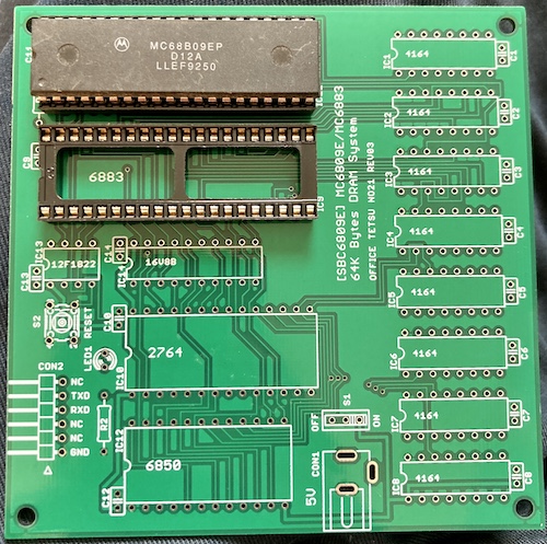
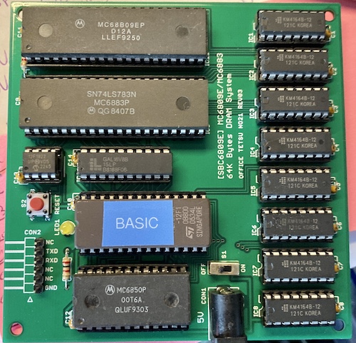
What are the parts on this thing, anyway?
| Part | What is it? | What’s it do here? |
|---|---|---|
| 6809E | Motorola 6809 CPU; “E” indicates that it requires an External clock generator. | Processes centrals. |
| 6883 | Motorola 6883 “Synchrononous Address Multiplexer;” usually shares memory between the 6809 and a 6847 VDP (not present on this system) but also offers some decode. Sometimes also known as the SN74LS783. | DRAM refresh and decoding for same; decoding inputs to 16V8 GAL |
| 12F1822 | PIC microcontroller | Clock generation |
| 16V8B | 8-input, 8-I/O GAL | Address decoding (ROM, CIA) |
| 2764 | 8kB ROM | Boot software and BIOS for system |
| 6850 | Motorola serial chip (CIA) | Serial communication with controlling terminal |
| 4164 | 64K x 1-bit dynamic RAM | Stores memories of things the computer has experienced in the past, occasionally causing it pain in the present |
There’s also a small handful of passives. Power is provided by a DC jack expected to offer regulated 5V (centre-positive.) I had one of those jacks in my parts bin, and I didn’t bother to measure it before I chucked it into the board. Same goes for the 3-pin power switch, of which I had a random bag from some other hoarder’s collection. Your mileage may vary.
I did not have any right-angle 6-pin headers, and they felt a little cramped against the board when I thought about chopping up two 4-pin headers to make it fit, so I ended up using a straight six-pin header.
Once the MC6883 arrived from Utsource, I was ready to go.
Burning ROMs and GALs
The ROM is provided as an Intel Hex file, which is to say, not a binary file. BASIC9E_map1_slow.hex was 23,040 bytes long, which is a little bit more than the 8,192 bytes in a 27C64 EPROM. I got a utility called hex2bin from GitHub, built it, and ran it on the hex file.
After a bunch of warnings about overlapping records, hex2bin spit out an 8kB bin file that it claimed had a starting address of $e000 , which looked right to me. This file wrote fine to the ROM, but it would be a few more weeks of waiting for parts before I could check.
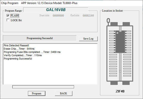
As for the GAL16V8, I had never written one of those before. Sure, I’d hoarded a lot of 22V10s over the years, for speciously-defined “future projects,” but never actually written anything to them. I was happy to find out that the TL866 could program them, even using the minipro command-line program.
% minipro -p GAL16V8B -w sbc6809e_datapack/sbc6809e_gal.jed
Easy!
The same went for the PIC12F1822: thankfully supported by the TL866. What a great piece of hardware. Curiously, the minipro software had no problem directly programming using a hex file for this device.
% minipro -p PIC12F1822@DIP8 -w sbc6809e_pic.hex
Unfortunately, I would later find that this command didn’t exactly work. More on this in a bit.
Forward to BASICs
Before I could run the SBC6809E, I had to figure out what the polarity of the DC plug was. I had looked at the schematics previously, but completely forgot what they said. In a pinch, I did what I would have done without schematics, and used the continuity tester on my multimeter to find whether the tip or sleeve of the DC jack went to ground.
I put one probe on a known ground (in this case, the GND pin on the serial header) and then tested the tip and sleeve of the jack in continuity mode. The sleeve beeped, which told me that the sleeve must be negative. Therefore, the DC jack for this thing is centre positive. I made a note in silver Sharpie on top of the jack so I wouldn’t forget.
Unable to find my other 5V barrel supplies, I picked a cheap Amazon 5V brick to run it, and set about on my adventure. For communication with the host computer, I picked a mega-cheap CH430 USB-to-serial adapter that I had in my desk drawer.
After connecting everything, I flipped the power switch, an LED came on.. but nothing. I tried to flip TXD/RXD on the adapter, tried a few different terminal programs, and still nothing. The MC6883 and the MC6809E were both getting warm (the former more than the latter,) but there was no indication that anything was going extremely wrong.
PICking Winners and Losers
At this point, I decamped for the workbench, where I got out my logic probe. With its help, I was able to determine that there was no activity on the 6809E’s data pins or address pins. Nothing was going on in the RXD or TXD pins on the serial header, which I inspected as a sanity check. More concerningly, the CPU’s pin appeared to be stuck low, except for a periodic ‘flup’ out of the logic probe’s speaker. It seemed like there were clock signals on the Q and E pins of the 6809E, one of which, E, is generated by the PIC, but whether they were any good was hard to tell from the logic probe alone.
I rolled out the scope, and I saw a 4MHz clock signal on pin 3 (E), a signal connected to the active-low reset button on pin 4, a 35-ish kHz clock signal on pin 6 ( on the 6883, maybe horizontal sync?) and the CPU signal coming out of pin 7 of the PIC was stuck low.
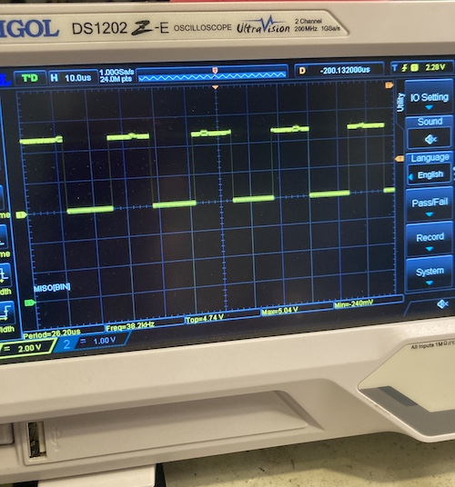
Most of these seemed correct except for . I quickly swapped out the 6809E for another one on the bench to make sure it wasn’t a dead CPU, and the problem persisted.
I checked the PIC source code. That code looked sane – it set a couple global parameters that seemed good, and issues a reset on power on by pulling the reset output pin low for 200ms and then high.
I pulled the 6809E out of circuit entirely, and was still constantly low. At this point, I pulled the PIC12F1822 and reprogrammed it in the Windows XGecu programming tool, thinking that maybe I had missed some command-line option that everyone who works with PICs regularly would know to provide, but that I didn’t.
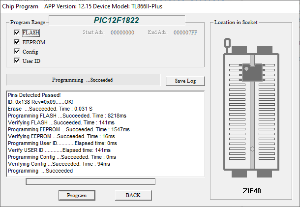
This worked out very well: after reflashing the PIC12F1822 (and rewriting its EEPROM area) I plugged it back in, and now I had a properly working pin! There was even CPU address bus activity for a short burst at startup.
At this point, I put the scope on the TXD and RXD pins of the serial header, but I didn’t see any activity. Just to make sure, I plugged it into my computer, and didn’t get anything on serial there either (obviously.)
Out of desperation, I also reprogrammed the GAL16V8 using the XGecu Windows software, but this made no difference.
I noticed at this point that the MC6883 was getting warm. Like, really warm. Not “put into the socket backwards” hot, but bad enough that I was worried the chip was bad. And that was an expensive, uncommon part – I decided that I would rather abandon the project entirely rather than buy another.
In my despair, that’s when I noticed something else funny about the board I had just populated with my own two hands.
RAM Testing
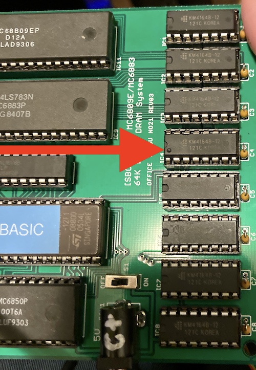
I noticed that one of the 4164s didn’t match the others. It was at this point that I remembered I didn’t test the 4164s prior to jamming them in the machine. If one of them were badly shorted, or otherwise popcorned, the MC6883’s DRAM controlling logic could be pulling a lot of current trying to fight them.
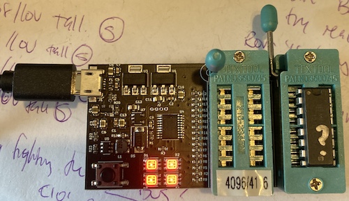
I had no excuse for not testing these salvaged AliExpress DRAMs. I did, after all, have a very fancy DRAM tester, made by Simon Raybould. I used the 4-bit version of this tester to check out the Sanyo MBC-555’s glitchy video RAMs last year, and now it was the 1-bit tester’s turn.
I plugged in the weird-looking KM4164. The RAM tester went away, flickering its little lights for a few seconds, and then came back: all green. This test was repeated with the rest of them, eventually turning up two (out of eight!) KM4164s that immediately went red on the test.
The only difference I could tell between these chips and the good ones was that the good ones had an ejector mark on the bottom reading “JAPAN,” and these ones had an ejector mark reading “USA” next to a rectangle relief. Absolutely remarked AliExpress parts, but I do wonder what these used to be.
The bad two were replaced with two new (also remarked) KM4164 chips that tested out properly. Now when I powered on the system, the MC6883 stayed cool. Ah ha!
Test Drive
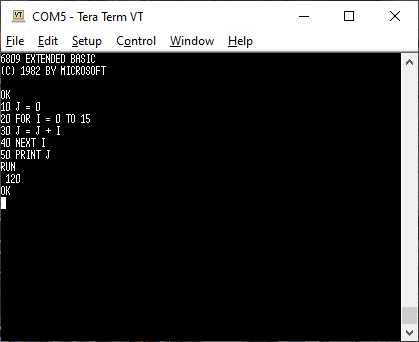
I did have to flip the TXD/RXD pins before it would work, as is legally required every time I use a USB-serial adapter. Tera Term Pro soon filled with the glories of the SBC6809E’s ROM BASIC:
It was a little late at night, so I was having trouble coming up with creative BASIC programs to run on it. I figured Celsius to Fahrenheit conversion would be a good one:
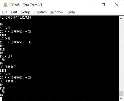
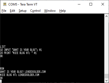
And maybe see if INPUT worked the way I remember it:
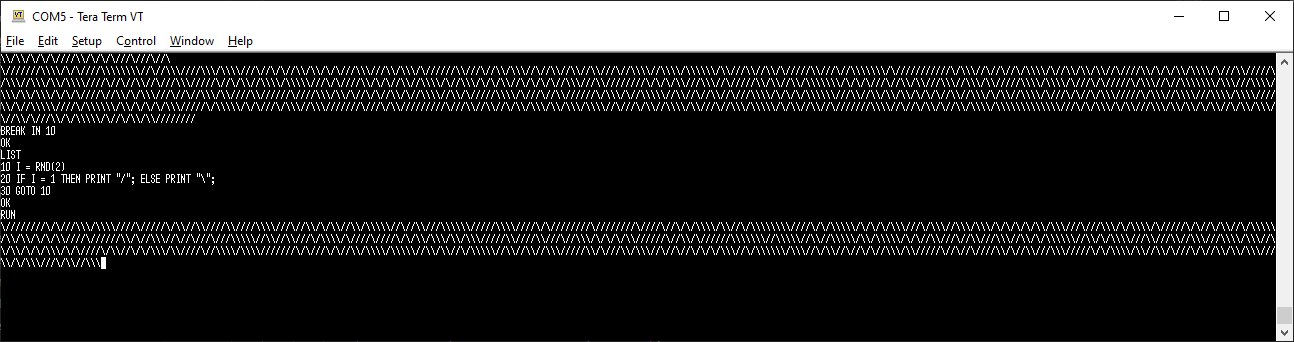
And then the classic “maze” program, although with this font it doesn’t look great. It also was inserting a hard line break every 256 characters so I just widened the window to that width so it wouldn’t break up the text.
I also decided to write a simple Fibonacci program. No need to recurse with a nice ugly loop:
10 A = 0
11 B = 0
12 C = 0
13 TARGET = 25
20 FOR I = 0 TO TARGET
30  IF I = 0 THEN C = 0
40  IF I = 1 THEN C = 1 ELSE C = A + B
50  PRINT C;
60  A = B
70  B = C
80 NEXT I
This produced the expected result.
Because the BASIC is more or less a direct rip from the CoCo BASIC, I found it useful to use Brad Grier’s HTML5 port of the “Mocha” CoCo emulator to test and debug my programs before firing up the real board.
Something More Complex
There are a large number of BASIC Mandelbrot fractal demos out there, mostly to benchmark the performance of the computers running them. I’ll tell you this: the SBC6809E is not going to win any speed records. The runtime took at least ten minutes, during which I got bored and made a sandwich. It is pretty though:
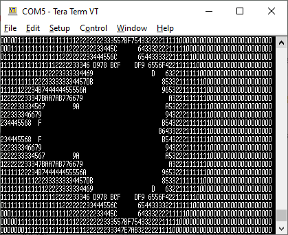
That program is relatively straightforward:
10 FOR Y=-12 TO 12
20 FOR X=-39 TO 39
30 CA=X*0.0458
40 CB= Y*0.08333
50 A=CA
60 B=CB
70 FOR I=0 TO 15
80 T=A*A-B*B+CA
90 B=2*A*B+CB
100 A=T
110 IF (A*A+B*B)>4 THEN GOTO 200
120 NEXT I
130 PRINT " ";
140 GOTO 210
200 IF I>9 THEN I=I+7
205 PRINT CHR$(48+I);
210 NEXT X
220 PRINT
230 NEXT Y
Conclusion and Next Steps
The SBC6809E board is great, and I am very grateful to CDP for sending me one, and to vintagechips for having designed it in the first place. If you have a spare MC6883 lying around, I can recommend building it.
Like any computer, I can’t leave well enough alone now that it works. I think there are a few good next steps for this board. Obviously, an external data interface that’s more than just “paste program code into TeraTerm” would be nice. Likely that would look like cassette tape, but if an expansion interface board is designed, it could even include something like SPI for talking to an SD card.
Using the CoCo’s MC6883 only for memory management is not an optimal use for that part, so I believe it would be very, very cool to create a secondary video sub-board that plugs into the socket. That board could provide a 6847 and some composite video output for this system, making a sort of half-CoCo with TV output. I’m not sure what that would require, but I’m interested in finding out.
There is room for lots more stuff on the ROM, and maybe even a ROM switcher. Perhaps it is finally time to write a 6809 Forth?
Fault Summary
None of these are the fault of the board – they are all caused by me!
| Fault | Remedy | Caveats |
|---|---|---|
| No reset signal on 6809E | Re-flash PIC using Windows XGecu | Still no idea what went wrong with minipro |
| MC6883 gets hot, no startup | Replace 2 bad KM4164 DRAMs |