Mattel's Little Friend
Tags: computer mattel aquarius pickups mod
As I’ve gotten deeper into the world of 8-bit computers, one mass-market, North American computer has resisted my attempts to obtain it. That computer is the Mattel Aquarius, and it is at last within my grasp. Or at least it would be, if it would act a little nicer.
It Is The Dawning of the Obvious Joke
What is a Mattel Aquarius? The simple answer is that it’s an el-cheapo Z80 based home computer from 1983. A longer answer requires a bit of a history lesson about the Intellivision, and its attempted growth into a home computer of its own.
When the Intellivision “Master Component” was originally released, Mattel promised that there would be an expansion released later that would turn it into a “real computer” capable of writing programs and saving them to tape. For various reasons - probably “not invented here” syndrome – this expansion project, the Keyboard Component, ran on forever. In fact, it ran on for so long that the FTC soon began fining Mattel for having made deceptive promises with the original sale of the Intellivision. These fines forced Mattel’s hand, and the Keyboard Component was all but killed by the release of the cheaper, less-fully-featured “Entertainment Computer System” (ECS) which obviated it.
Mattel still wanted to release a computer, and it turns out that Radofin, their manufacturing partner, made a cheap Z80 computer. They bought the rights to this computer, and planned to manufacture and distribute them to get some of that sweet, sweet 8-bit money. That computer is the Aquarius.
These computers did not sell well, especially not while Commodore and Texas Instruments were trying to kill each other on price. In fact, Mattel paid Radofin to back out of the deal, and bailed on the just-released Aquarius II entirely. Depending on the source, the Aquarius was on sale for at most four months in 1983.
Mattel Electronics would go on to blow an enormous hole in Mattel’s financials and go under in 1984.
So: a Z80 computer that was unpopular, came from a long line of failures, has unusual hardware, and killed its parent company? Sounds perfect for this blog.
What really interested me about the Aquarius, though, was reading about the Aqua cartridge. It adds a bunch of nice features to the Aquarius, but in order to do so, they had to defeat the Aquarius’ peripheral security.
For whatever reason, Mattel or Radofin wanted to prevent random people off the street from releasing cartridges and/or peripherals. To do this, the onboard PLA scrambles the contents of the external data bus, XORing it with a key that is randomized on startup (probably from being stored in a non-resettable latch.)
The writeup didn’t give me enough information to figure out how official peripherals would have gotten around this, since their onboard ROMs would not get a chance to run. So I decided I would try to get a machine of my own.
That particular mystery isn’t solved in this article: this is all about getting the machine, my first impressions, and fixing the incredibly bad RF output.
What About This One?
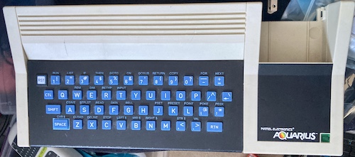
This one came from eBay, where the buy-it-now price hovered just above my target. Of course, the shipping was a little expensive, but it arrived in relatively good condition. It didn’t come with any peripherals, such as the common “Expander,” and it honestly looks a little bare with that cartridge slot all empty and alone.
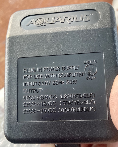
I immediately noticed that the AC adapter was hard-wired into the system. You can’t unplug it. This is good, because it has some really wacky – presumably unregulated – voltages on the back.
My first impression of this computer: it’s heavy. Both the hardwired, non-detachable AC adapter, and the computer itself, feel very dense. As for my second impression? The keyboard sucks. It’s got a rubbery, wiggly-key setup similar to the Spectrum, but the keys are hard-edged and a little bit too firm. Of course, that’s personal taste, but I don’t think anyone is going to collect the Aquarius for the joy of touch-typing.
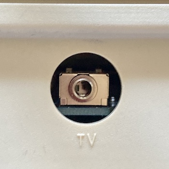
The video output on the Aquarius is strictly limited to RF. That video is generated by the Aquarius’ video chip, a Mullard TEA1002, which generates either PAL or NTSC from an internal 4-bit RGBI colour representation. It seems like on my particular Aquarius motherboard, the “PAL Phase Switch” pin is disconnected and the chip is fed 7.159MHz, which will make it produce an NTSC-compliant signal with some tuning1.
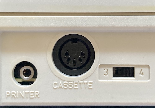
In addition to the RF and the hardwired power supply, the Aquarius features a full-size DIN connector, for tape loading. There’s also a curious 3.5mm stereo mini-jack, marked “printer.”
Does it work?
After giving it a quick inspection, I plugged it into the RF switcher that my Master System 2 uses, and fired it up on Channel 3. Nothing happened, although the power light was lit. I changed the computer and the TV both to Channel 4, and got a startup screen after a couple seconds of wiggling cables.
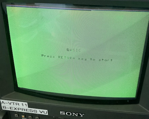
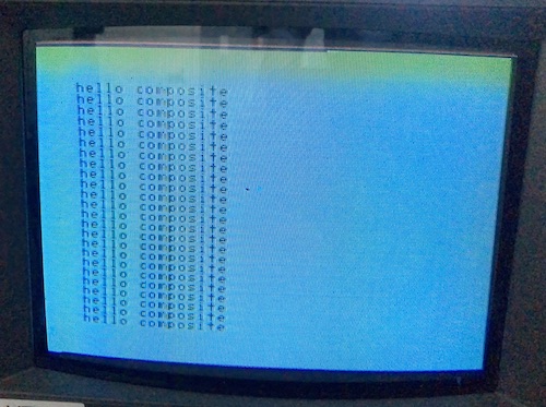
A very, very noisy startup screen.
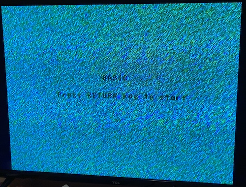
This screen cycled through background colours, which I initially thought might be a bad connection or some mistiming problem in the video. However, when I hit the return key to go to BASIC, the background went to and stayed this awkward teal colour. It’s slightly easier to read this in person than on these pictures, but it wasn’t great quality.
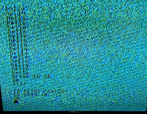
I typed out a simple program – I was very happy to have a working backspace key, unlike some other computers I can think of – and ran it. Sure enough, this was BASIC. The sign-on message when starting the interpreter bragged that their version of BASIC came from Microsoft.
Assembling the Composite Mod
Based on the RF quality I was seeing in the pictures above, I decided to abandon RF with extreme prejudice. Luckily, Sean P. Harrington has made an open-source Aquarius AV adapter. This board removes the original RF module and sticks a PCB in its place, using a 3.5mm TRRS connector for the audio and video output. Gerbers for the through-hole version were ordered.
When it got here, I noticed that the AV mod board featured some peculiar parts. Predominantly, there’s the Analog Devices AD812ANZ current amplifier, which costs $14 in single quantity. Some luck: Analog decided that they would send me one for free as a sample, which has rendered them an inadvertent (or unwilling?) sponsor of this project. Thanks, Analog Devices.
Being an Analog Devices part, its example circuit requires a ton of very precise passives to come with it. And since Sean based his AV-mod circuit off the AD datasheet circuit (by his own admission,) there’s some odd values of passive here too. Or maybe I’m the weird one, for not having 649Ω resistors and 2µF axial aluminum electrolytic capacitors.
As per usual these days, I had to wait a dog’s age to get the parts.
Getting Inside
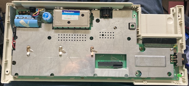
Getting inside the Aquarius is kind of a pain. Not only is the hard-wired AC adapter always in your way, but they chose to solder the RF shield onto the motherboard in a few places in addition to the usual “twist-lock” method. My Pinecil’s boost mode made quick work of these, and I was soon in.
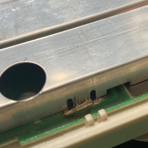
I was a little overzealous with the removal of one of the shield pins, and ended up tearing a corner pad. I submit myself to the judgment of the Mattel community.
One special note: the 10000µF main capacitor (as well as probably whatever capacitor is in the AC adapter) seemed to hold a charge for a really long time. I counted at least ten seconds of having the power switch on before the power LED began to fade. Make sure to discharge everything before you start monkeying around in here; I doubt it’s enough to be harmful, but it’s no fun to get zapped. Unless you’re into that kind of thing, I don’t judge.
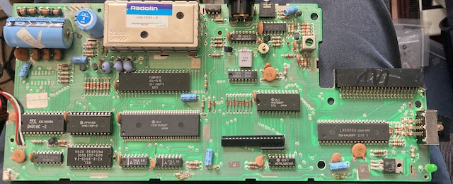
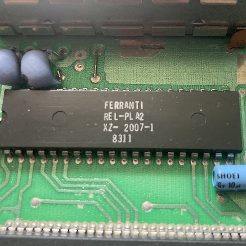
Now that the motherboard is exposed, we can look at some of the guts. There’s not much discrete on this - there are three custom ICs, including a Ferranti ULA:
- Ferranti REL-PLA2, ZX-2007-1, date code 8311
- Hitachi HD61K202P
- Unknown manufacturer REL ZX-2-2003-1A (609-2015001) M458938 date code 82/40 (24-pin DIP)
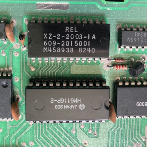
I think that last one may be a mask ROM, because of its position and size. “REL” likely stands for Radofin Electronics Ltd. Only the Hitachi HM6116 SRAM nearby is socketed, which makes me think it must have been one of the more expensive parts in the system, or that Radofin had a problem with yields.
This is kind of a bummer for clones, but luckily I don’t have to: Sean P. Harrington, the same fellow who designed the AV mod, has partnered with Frank van den Hoef to build a recreation of the Aquarius using an FPGA, the Aquarius+. And I thought I put a lot of effort into unloved systems.
The TEA1002 VDP is surprisingly tiny - just a little 18-pin narrow DIP near a crystal that dwarfs it. Its datasheet seems to indicate that it is a dumb colour/raster generator, and so the ULA is likely the thing doing the address generation, video-RAM reading, and figuring out which colour to tell it to draw at that moment. Still, an impressively tiny part for this purpose, maybe because it’s a bipolar IC.
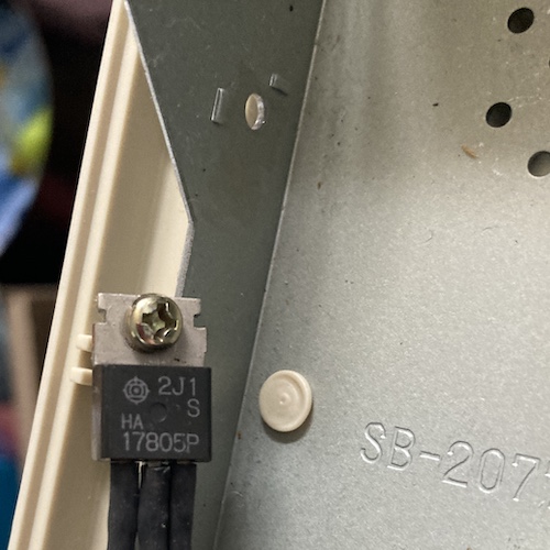
7805
While I had the system open, I decided I would stick in a 7805 voltage regulator replacement. The original voltage regulator is probably fine, but they do generate a lot of heat. I chose a nice Traco TSR 1-2450, which generates essentially no perceptible heat: it has much higher efficiency than a traditional linear voltage regulator.
On other machines in my collection, these Tracos have worked great for me. The only major downside is the increased noise produced by it being a switch-mode regulator. With so few Aquariuses in the world, I reasoned that reducing the heat inside the system and extending its lifespan would be a good idea. Maybe future generations will thank me, but probably not.
I desoldered the old wiring harness and soldered the 1-2450 directly to the old holes. There’s plenty of vertical room: it’s not even as tall as the socketed chip next to it. I did have to tilt the thing a little bit to the side to make sure I had tons of room for the mounting screw.
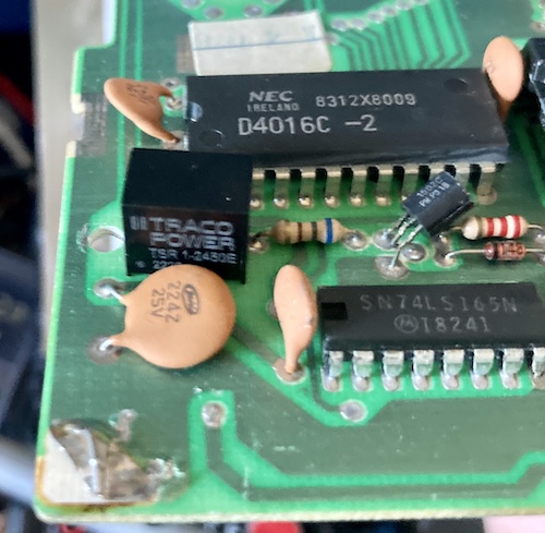
Please don’t look too closely at that torn pad in the corner. I said don’t.
AV Mod Install
Removing the old RF modulator was actually easier than removing the shield, even though it had a combination of twisted and soldered tabs holding it to the ground pours of the motherboard. My Pinecil again made short work of all this, and the desoldering gun slurped it all up. I only burned my fingers a few times.
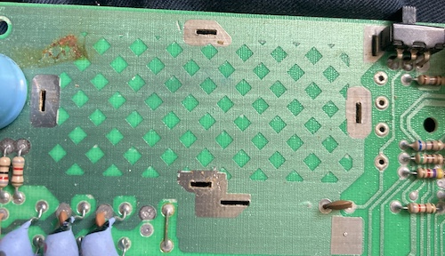
One neat trick is these little blobs on the board: you can cut them off to provide two 1.6mm-thick spacers. Shimming the board with both of them makes the board sit at the exact right height (3.2mm, in case you’re bad at math) such that the TRRS jack is centered where the RF jack used to be.
In the official install video, the unattached spacers seem to slip around a bit when the board is flipped over, so I cheated and stuck them onto the bottom of the PCB with tape.
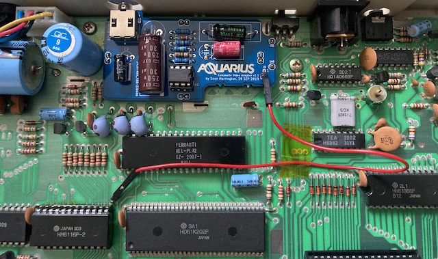
The AV mod board drops right into the ground pins, video, and sound where they come into the original RF modulator. Unfortunately, it doesn’t have +5V in that position, so you have to run a jumper wire. I cleared out a nearby via, as per the instructions, and dropped in a right-angle pin header. Then I ran a jumper DuPont wire to a right-angle pin header on the AV board. A DuPont wire is not really meant for permanent installation (especially from a cheap Amazon seller) but I like that this makes the mod semi-reversible. I taped it down just to minimize the chance that it will come loose, but it feels like it will last for awhile.
Test It! Test It!
I was lucky enough to already have an AV cable with the required pinout, which my notes indicated was a “Sony” pinout. To make sure that anyone else would also be able to make use of the computer, I put the cable pinout on a label on the bottom of the case.
After connecting it up to my test PVM, I flipped the switch, and the Aquarius beeped to life. Sound, video, power: I would say this was successful.
Fun fact: this screen is done in BASIC. If you write a program and accidentally hit the giant “Reset” button on the keyboard, you can hit Ctrl+C at this screen instead of Return, and you’ll be returned to your program. Pressing Return, on the other hand, invokes the NEW command, which clears your program buffer.
As I’ve said before, this PVM has a lot of problems with blue backgrounds: I was fairly sure that this green stripe at the top of the raster was because of the set, and not because of the AV mod. Still, look how sharp it is.
Now I wanted to write a colour bar program to test it out. Friends: this is where things get interesting. While the Aquarius claims to have Microsoft BASIC, there is apparently a pretty wide variance in exactly what features are in each implementation of Microsoft BASIC.
See, on the PC-6601SR, making your text a different colour is as simple as typing COLOR n and then printing like normal. Observe:
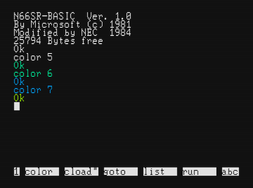
Even without graphics primitives, you could easily write a loop and fill the screen with some solid character.
On the Aquarius, changing colour is, well, not as easy. Here, I’ll quote the manual for Aquarius Extended BASIC:
REMINDER
The formula for specifying foreground and background color with the POKE statement is:
POKE (Screen position), (foreground color) * 16 + (background color)
Instead of using the formula, you can use numbers listed in the color table on the next page. Find the foreground color you want in the left column and the desired background color in the top row. The number at their intersection is the number you use in your POKE statement. For example, to set position (0,0) to a yellow foreground (3) and blue back-ground(4), the statement would be: POKE 12328,52
That’s because 52 is the number at the intersection of foreground 3 and the background 4 in the table.
Yeah, that’s right. To change text colour, you must do a manual POKE into the palette RAM.
Plus, the example is wrong. After a few minutes of piddling around in MAME wondering why it didn’t work, I found out that the character memory is at 12328, and the colour memory starts 1024 bytes later2, according to the “Aquarius Guide to Home Computing” regular BASIC manual that came with the computer.
After some more trial and error, I ended up banging out a very simple colour bar program:
10 PRINT CHR$(11) ' Clear screen
20 CS = 12328 + 1024 ' Set CS to start of colour RAM (0,0)
30 FOR R = 0 to 23
40  FOR C = 0 to 29 ' Only 30 wide since 40 / 16 is not a round number
50   POKE CS + C, C / 2
60  NEXT C
70  CS = CS + 40 ' Advance to next line
80 NEXT R
200 X$ = INKEY$ ' Loop until key strike
201 IF X$="" GOTO 200

Aargh! Even the colour indexes are weird! I would have expected the latter half of the colours to be in the same order as the first half, but desaturated. Instead, they’re in what seems to be reverse order?
Now that we know it works, let’s try this colour bar program on my sufferin’ Samsung 910MP. I wanted to make sure it’s just my PVM and not the mod itself needing a lick of tuning.
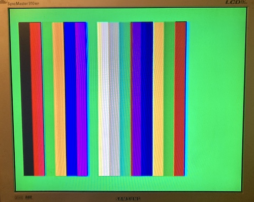
It looks fine to me, outside of some fringing. Let’s try it on my cheapo USB AV capture device:
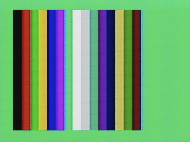
I would say this is a successful composite mod! Thank you again to Sean P. Harrington for developing such a nice-to-install mod for this unloved little computer.
What’s Next?
There’s a lot of things I would like to try out on this computer, now that I know it works and that its video output fits into my preferred workshop setup.
For starters, the main goal of acquiring one of these computers was to understand how aftermarket hardware interfaces with the “protection” system. I would like to get a legitimate game cartridge3 and tear it apart, to see if it has some kind of magic handshaking logic that authenticates itself to the ULA and unscrambles the data bus, or if they do something really simple that I just can’t see based on what little I’ve been able to find out about the ULA.
Next, I’d like to get a Mini Expander. The Mini Expander peripheral makes this computer into more of a usable machine, adding more sound voices through an AY-3-8910, joypad ports, and an extra cartridge slot to be used for a RAM upgrade. Lucky for me, Mr. Harrington has also produced a clone of that peripheral, so I will likely make that my next kit build, rather than dip into the angry waters of eBay.
Last, I’d like to build my own peripheral. It would be completely ridiculous to bolt, say, FujiNet to the cartridge slot, and involve a lengthy project whose time would probably be better spent on another system, with more software.
I think there is probably a good starter project in “make your own game cartridge,” or even something only faintly ridiculous like a YM2203 FM cartridge.
Until next time, remember to keep your fingers away from the Reset button.
-
My limited (and likely incorrect) understanding is that PAL and NTSC are very similar, except that PAL carries its chrominance at a different frequency, and sends alternating lines in inverse phase, which limits overall chroma information but makes the colour reproduction more resistant to noise/interference. ↩
-
These seem like very strange addresses at which to mount video RAM data, and they don’t make any more sense when translated into hex ($3028 and $3428 respectively.) $28 is exactly 40, which just so happens to be the number of columns. You can write one row up, outside of this area, and it’s visible in MAME. The top left becomes 12289 in that case – 12288/$3000 overwrites the contents of the screen border. Maybe Mattel told us $3028 is (0,0) for overscan/safe-area purposes? Very odd, and maybe deserving of an experiment on its own the next time I do a mini-update roundup. ↩
-
Tron: Deadly Discs seems to be the cheapest game, but it’s well over a hundred bucks after shipping. If you’ve got an Aquarius game booting around in your basement, maybe we can work out a deal for a Soggy or something. ↩