No Highs? No Lows? Must've Decomposed
Tags: appliance bose-wave-radio repair
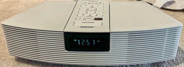
My friend issued me a 90s Bose AWR1-1W Wave Radio clock radio to repair, with some sentimental value. For those who are unable to rock, we solder you.
Why bother with this repair? Aside from the sentimental value, if the repair is simple enough, it prevents this piece of hardware from ending up on the e-waste pile. E-waste is a necessary but horrific industry that produces enormous pollution, exploits labourers, and shifts toxic waste from the country that produced it to the developing world.
Returning this radio safely to function means that all the materials harvested to produce it – the plastics, the rubbers, the copper, the silicon – can keep serving a useful life without having to be recycled.
I also wanted to check out a piece of Bose hardware up close: there are a lot of audiophiles who will look down their nose at anything badged by Bose, and I certainly am not the kind of person to buy stereo gear of my own accord. Maybe I’d get a good laugh out of it?
If you need another justification: it’s a survivor. Although a computer from the early 90s can have lots of problems, it is truly impressive that an electrical appliance has lasted for over thirty years being plugged in nearly 24/7. It’s earned a small service, if you ask me.
Regardless of the reasons, I figured I would give it a shot, and I was pleased with the results.
Problems
My friend told me that there were a large number of problems with this relatively old clock radio.
- FM radio stopped working a few years ago, so he switched to AM, which then also stopped working recently;
- Sometimes the screen doesn’t work, or all of the screen is active at once, or it glitches;
- Sometimes it’s very quiet.
Disassembly
This went really smoothly. I was actually surprised. After removing four self-tapping Phillips screws from the bottom, I just had to shake the top off to split the case. Then, I disconnected a ribbon cable and what appeared to be a power supply cable, and moved the entire assembly aside.
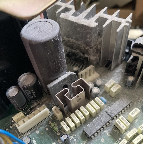
The mainboard/power supply/transformer/ports assembly on the bottom is very dusty and filled with cat hair. I took this out to the driveway to blow out with my XPower blower, which instantly made a big difference to the condition of the board.
Of course, I didn’t take a picture of that freshly cleaned board, so you’ll just have to imagine it.
The board is full of generally decent quality components (STMicro op-amps, Nichicon 105°C capacitors, car radio stereo amplifiers) with available datasheets. None of this is a particularly exotic or high-performance component. The Bose “innovation,” if anything can be said to be one, is the wave part of “wave radio.”
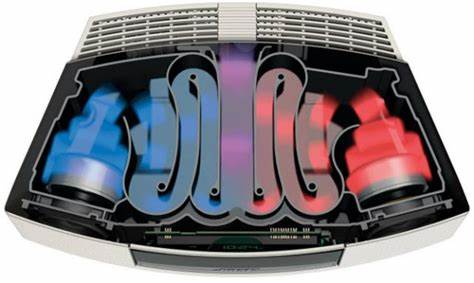
This tiny unit, with incredibly tiny speakers, is boosted by a snakelike “waveguide” path through the back of the plastics, which is claimed to do some kind of harmonic magic to the sound. I would have liked to take an actual picture of it, but the top case seemed to be glued together, and my bravery is limited when working on someone else’s gadget.
Does all this wave magic work? I didn’t know yet, because it was still broken.
Top Case
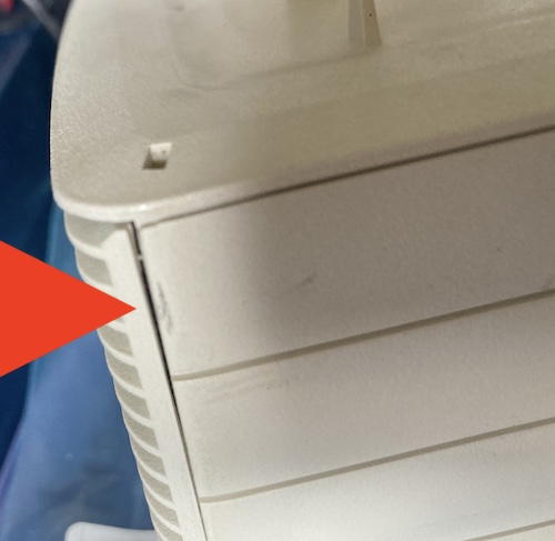
After looking at it a bit, I decided that I would also pull the screen assembly apart. I grabbed the white top and noticed that something had been prying at the speaker grilles previously. I did the same, and popped them loose with my fingernails, then worked around the perimeter with a spudger until two more clips at the top released, exposing the VFD board and the speaker cones themselves.
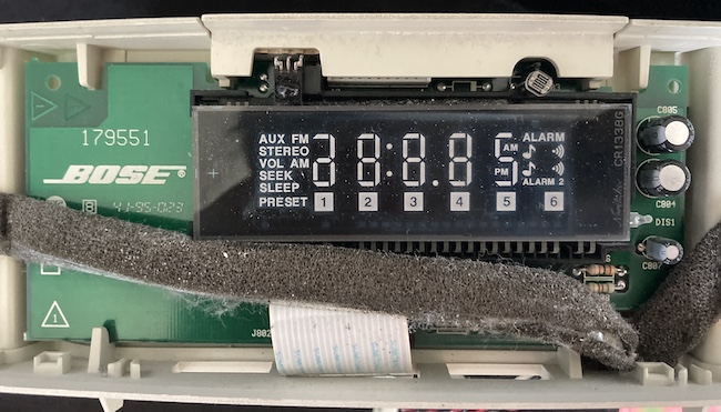
This beautiful Noritake VFD is socketed into a driver board that appears to have a phototransistor for the infrared remote, but I’m not sure what the light sensor on the right side is for. Maybe automatic dimming of the screen at night?
Although I didn’t take a picture of it, there was some kind of fat, high-density DIP underneath the VFD. I am assuming this is the microcontroller responsible for the stereo’s brains.
Repair Phase 1
For my first journey through the board, I focused on looking for bad solder joints, and other parts that were obviously blown, burned, or damaged.
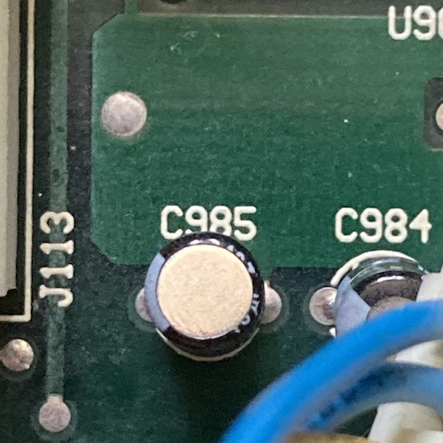
I found some caps with their skirts pulled down and dull-looking solder joints, like C985, but it was hardly a smoking gun. They later checked out fine on an ESR test, so I put them back in.
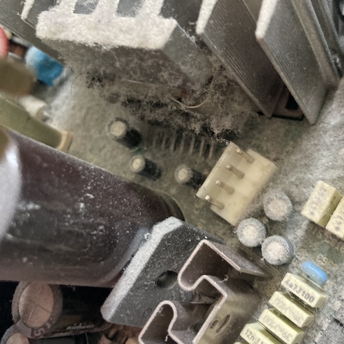
After removing the transformer (a fight with shrunken case plastics, and maybe glue,) I was able to pull the motherboard out. I immediately noticed that this dual coil, L1, had a broken plastic frame and was just able to be wiggled around loosely in space.
Based on this damage, I suspected that the clock radio had been dropped in the past, and this plastic frame near the backside of the case took the brunt of the impact. This probably wasn’t good for the coil, but neither of the two pairs of wire had broken from their solder joints, so it was probably still working. For now, I quickly jabbed some gel super glue onto the corners of the broken frame and moved on.
I noticed some dodgy-looking solder joints on the high-density DIP amplifier IC sitting under a shield near the south end of the board. Looking at them under the loupe, I saw lots of little hairline cracks in the solder. Reflowing these with new solder was not a big challenge at all, but there was a lot of it to touch, including some very obvious bullseyes.
Eventually, I decided that I had soldered enough joints for this first phase.
Quick Test
I was kind of a dummy and didn’t test the machine when it first arrived, so I decided that now would be a good time to test and see if I fixed anything. I assembled just enough of the machine to test, and plugged it in.
Immediately, I saw a messed-up screen (almost every segment was lit) and an incessant loud AC-like hum that slowly got quieter as I waited. Eventually, the machine konked out on its own, and then came back up, with slightly fewer segments lit. This cycle repeated a few times. Probably still have at least one high-resistance cap in here, and it is taking a long time and lots of current to charge. A lot of the “dark” segments also flickered dimly, which further made me suspect some failed filtering.

At this point, I decided to make like the Fonz and started rapping with my knuckles around the case of the stereo. Not hard: just enough to jiggle things, and potentially reconnect any bad solder joints. Eventually, I hit near the lower front of the board, and the screen changed. Repeated hits here made the screen flicker, which seemed to confirm my theory that we were also dealing with intermittent contact somewhere on either the display or motherboard. Although a lot of the periphery of the VFD was still screwed up, the stereo was now starting to count up through FM radio stations without settling on any.
The CPU was alive! I was able to turn the volume up and down, tune by hand, and switch between AUX and RADIO modes. Putting it into AM radio and looking for a local channel, I had AM radio. I was actually a little shocked how clean it sounded for AM radio.
Get Into The Tune
After opening the case and removing the board, I made sure to discharge the 10000µF capacitor. I had left it for a few hours, unplugged and powered off, but it still had enough charge to take a long time to discharge. I wouldn’t want to have accidentally touched it, or blown up my ESR meter, or my desoldering iron.
Next to it was the 1000µF/35V bulk capacitor that I had seen fingered in other repair posts about this system. It seemed like a likely suspect: installed next to a heat-generating element, a little undersized for its voltage, and always powered, regardless of whether or not the stereo was “on.”
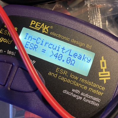
When I removed this capacitor from the circuit and measured it with my ESR meter, the meter reported “In-Circuit/Leaky” and told me that it had a resistance value too high to bother measuring, over 40Ω. Yeah, that would probably do it.
I didn’t have this cap on hand, so I ended up ordering a small handful of Rubycon YXJ, rated to 10,000 hours @ 105°C. And then I got tired of waiting, so I dropped by my local electronics shop, and bought a set of whatever they had on the shelf for a buck a piece. Gotta support your local shop!
After installing the new cap, reflowing several joints, and test-fitting everything, the radio jumped to life and worked fine, including FM tuning.
Auto-tuning (seeking) seemed to not be very good, only settling on stations that were extremely “loud,” but it did work. I’m not sure if this is a design flaw in the device itself, as manual tuning worked fine.
I gave it two hours of the local college radio station, and then decided it was good enough to return home.
FM audio quality isn’t quite as impressively better as it was with the AM; I’m assuming there’s a lot of filtering going on with the AM radio to get rid of common sources of noise. FM just sounded like, well, FM radio from a decent-quality car stereo. My life remained unchanged by this.
Detail Work
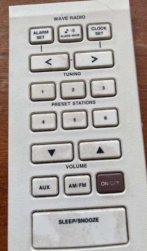
The rubber membrane number pad on the top had picked up decades of grit, so I decided to pull it and clean it with a baby wipe. This took only a couple minutes and made a big difference. Rubber membranes like this always pick up a lot of gunk, especially when they face upward and receive the gift of dust from gravity.
I also wiped down the green lens on the front that covers the VFD: even though it was still scratched, getting rid of the dust and grime from the inside and outside also made the whole system look newer.
Conclusion
I was happy to fix up this little radio: it’s not much in the grand scheme of things, admittedly, but it was repairable with only a few cents in parts and a couple hours of my time. If everyone fixed up a busted clock radio, then we wouldn’t have to keep making new ones. And then we could save those resources to make new 8-bit computers instead.
Repair Summary
| Fault | Remedy | Caveats |
|---|---|---|
| Dirty inside | Blow out cat hair, dust | |
| Broken L1 choke can be wiggled by hand | Glue up frame | |
| Can’t tune to FM, glitchy screen and noise on startup | Replace 1000µF/35V capacitor |