NEC's Apple Clone
Tags: computer nec video crt jb-1260ma repair
You really shouldn’t go poking around on eBay when you don’t have something you’re looking for. How many times has this happened to you? I saw this monitor, the shipping price was reasonable, and I made a low-ball offer. The seller immediately accepted that offer without hesitation (uh-oh) and now I have a new monochrome composite CRT to fix.
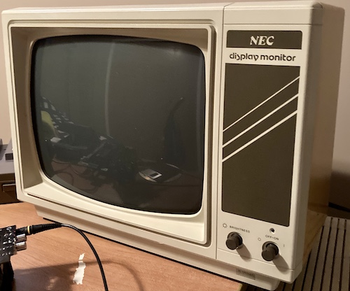
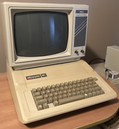
This CRT monitor is an NEC JB-1260M(A), and I think we can guess what the “A” stands for. NEC Home Electronics was apparently so enamoured with the Apple II that they decided to make a version of the 1260M monitor that would fit well with it. There’s Motter Tektura font on the front, some very Apple II+ looking 70s diagonal stripes, and even the plastic colour matches an early Apple II. This same monitor was also sold as the NEC PC-6041 starting in 1981, often being paired with the PC-6001/NEC TREK as a budget option1.
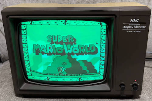
The NEC PC-8500 manual refers to this model of monitor as “affordable green,” and those are two of my favourite words in the English language. In 1985, it was being sold for sixty dollars.
In case you’re curious, that non-A version of the JB-1260M looks like this, according to a Yahoo Auctions listing I found for the set as this article was getting ready to publish. It’s not a great colour match for the beige-and-orange PC-6001, making me suspect it was originally meant to pair with the darker PC-8001mkII case:
That’s enough model history. Back to my set, the most important one of all. The sticker on the back tells us that both halves of the case are high-impact polystyrene. For some reason, though, only the rear part of the case has dramatically yellowed where it’s been exposed to sunlight. There’s a convenient carrying handle there, but I always prop my other hand under the set while carrying it, in case today is the day that the yellowed plastic decides to crumble.
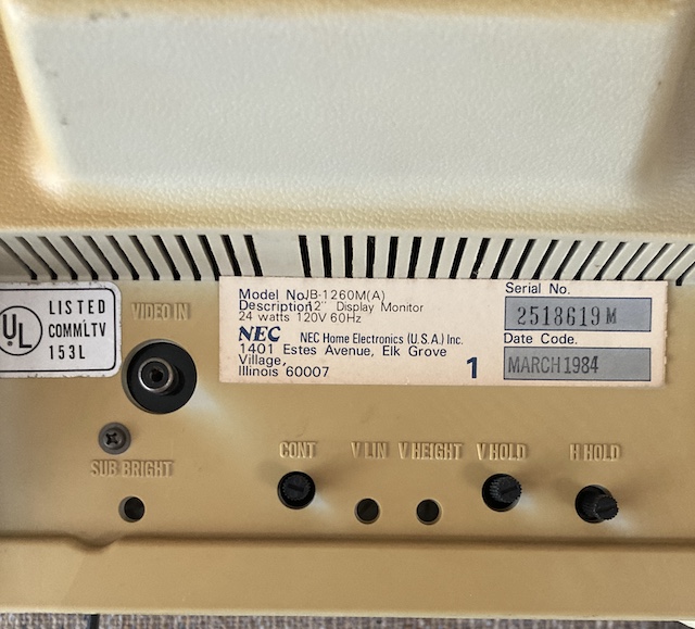
There’s only one port: composite video in. Again, it’s a monochrome tube, so luminance is really all you get from this puppy. There are a few adjustments: sub-brightness, contrast, vertical linearity, vertical height, vertical hold, and horizontal hold. That last one is a little unusual; it’s certainly not an adjustment that’s made so readily available on the Apple Monitor ///, for instance. We’ll get to this adjustment in a bit.
How about that build date of March 1984, huh? It’s a little hard to believe that NEC Home was pumping this thing out less than a year before my late-1985 PC-TV151. Maybe they were even built on the same assembly line: the achingly beautiful JB-1201 NEC Character Display seems to have been made for at least as long.
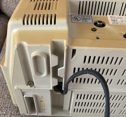
Because the power cord enters the television set near the front of the case, there’s a neat little zig-zag path moulded into the back case so you have a place to gently tuck your power cord. I thought the void at the front might be used to stow the plug, which would be great for storage, but I couldn’t get it to work nicely.
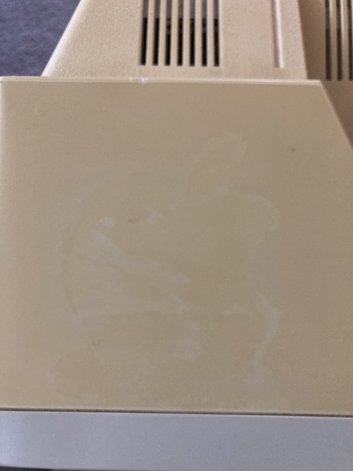
This monitor was definitely used with an Apple II - there’s a ghostlike outline of where a vintage sticker used to sit.
Why buy this monitor at all? Well, mostly because it looks neat. The “Apple-look” is an interesting artifact of the time period, when Apple was the company to beat, and even NEC was interested in courting that market with an inexpensive option for a matching monitor. I certainly don’t need another monochrome composite tube, but I do need something that looks cool in my hoard collection.
Analysis 1: Low-Hanging Fruit
Of course, the reason I got the monitor for a low-ball price is because it offers low-ball functionality. In other words, it doesn’t work. While the power switch at the front works, and the power light comes on, no signal appears, I can’t hear any refresh noise, and it doesn’t seem like the tube is doing anything.
I had an immediate suspect: the “horizontal hold” knob felt very loose and I could even pull it out a bit. If there’s a broken pot, like on my PC-6001 volume control, then it would probably screw up all kinds of things.
I took the set briefly apart to look for obvious troublemakers. I found a dead spider and vacuumed him(?) up. Sorry, buddy.
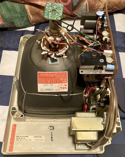
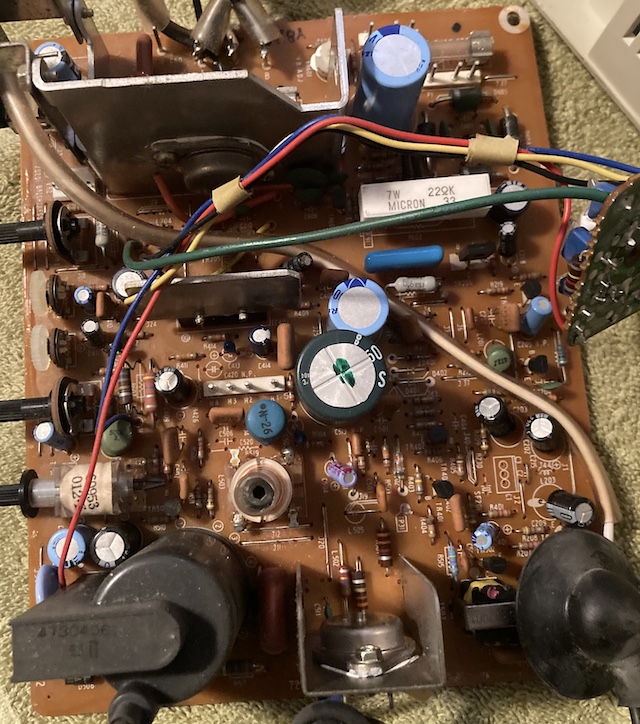
Other than my arachnid predecessor, the set was gorgeous inside, without much carbon “soot” scattered around the interior. Notice the giant transformer connected to the power switch: CJ suspects this, like many composite monitors of the era, is a former hot-chassis TV that was quickly turned into an isolated composite-friendly set using a 120-to-12V transformer. It certainly makes more sense than the TRS-80 monitor using an externally-powered opto-isolator for composite input!
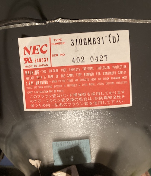
The CRT inside this set is a 310GNB31(D), which is apparently the same tube used in some models of Commodore PET. It looks like there are several tubes compatible with this configuration.
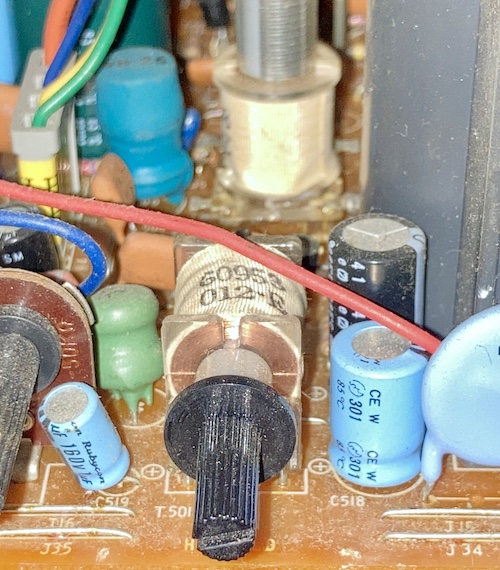
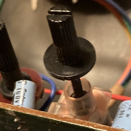
The horizontal hold knob turned out to be connected to this neat coil, and it didn’t seem like it was damaged in any way.
I was able to pull it out about this far, but no further:
After closing everything up, I connected the set to my Kill-A-Watt to figure out how much current it was drawing, and was surprised to see that it was reported as 0.22A at 132V: 29 watts. If you scroll back up and look at the picture of the back of the set again, you’ll note that the sticker on the back says “24 watts.”
The sticker on the back usually indicates average steady-state consumption, and you can take it with the same grain of salt that you’d take a Craigslist poster’s description of fuel economy. Especially since a different sticker on the back of the very same monitor says it consumes 0.3A at 120V.
I would expect much more than the “average” in order to bootstrap a tube to life, but that’s still a lot of wattage to pull for nothing happening. Five more watts than average is not terribly dramatic, but at least it feels like something is going on.
I could definitely hear a faint pulsating hum that is probably the giant transformer being energized, which was to be expected, as the power light is turned on. Since monochrome sets don’t have degauss, I couldn’t listen for that classic bonk to hear if the high voltage was working.
Analysis 2: Power Squinting
When I opened the set this time, I noticed there were some helpful stickers on the inside of the rear clamshell.
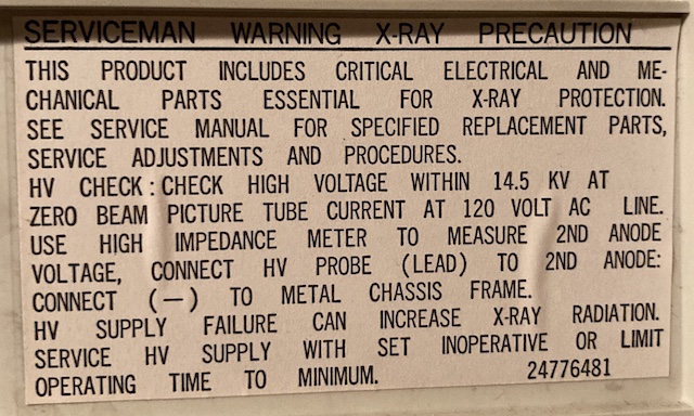
Serviceman warning, x-ray precaution.
This product includes critical electrical and mechanical parts essential for x-ray protection. See service manual for specified replacement parts, service adjustments and procedures.
HV Check: Check high voltage within 14.5 KV at zero beam picture tube current at 120 volt AC line. Use high impedance meter to measure 2nd anode voltage, connect HV probe (lead) to 2nd anode: connect (-) to metal chassis frame.
HV supply failure can increase x-ray radiation. Service HV supply with set inoperative, or limit operating time to minimum. Part number 24776481.
This sticker implies the existence of a service manual, which is an exciting concept. After looking, I’d found English-language NEC service manuals for other monitors, but not this one. Can’t win ‘em all.
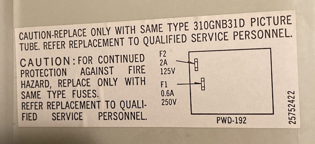
The other sticker indicates which fuses are present on a PWD-192 chassis board, and their values:
- F1: 0.6A, 250V
- F2: 2A, 125V
I checked both fuses, and they were fine.
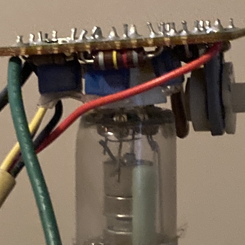
It looked a little bit like the neck board had come loose on one side. I pulled and re-seated it, and did a test, but I didn’t notice any change in function, nor did I see the heater come on through the vents when I looked at the set in a darkened room.
After opening the set again and discharging the tube, I pulled the board. This is a little annoying, because the board is soldered into the neck board, which is in turn soldered onto the ground wires. The heavy transformer is also soldered onto the mains power pins, along with the power cord, so things are not especially “portable” from one workbench to another.
With more room to work, I looked around for shorted tantalum capacitors, and found none. I determined that the resistance between the emitter pin and the case (collector) of the 2SC1618 was 26Ω, which isn’t particularly suspicious.
After tracing back the “K” connector to the front panel LED, I determined that the LED was running off of 12V with a very large series resistor to provide current-limiting for that LED. Given the voltage drop on that resistor, I had to assume that we were getting at least 12 volts. That means most of my supply was good. Sometimes the heater is difficult to see on some sets, including apparently this one.
Working my way around the board, I found that the resistance between the emitter and base of the 2SC940 horizontal output transistor at TR503 was only 2Ω. That’s not many ohms, but it’s also not zero.
I wasn’t entirely sure what the failure of a horizontal output transistor would do: I assumed that it would result in a super-bright vertical line, which is not what I was seeing. Visually, I determined that the emitter pin was connected to ground.
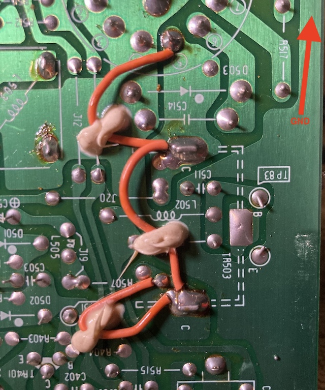
I’m not sure why this bodge wire is here. It seems to be connecting areas that are already visually connected. Maybe they needed a little extra current carrying capacity to avoid jitter?
Since it would be a pain in the butt to remove it and involve my hated enemy thermal paste, I decided to desolder just the emitter and base wires from the board, so that I could check the transistor for shorts out of circuit.
Looking at the NEC JB-1201 schematics, which are the only ones I could find, the 2SC940 transistor’s base is driven by a horizontal drive transistor, a 2SC1318. It’s isolated through a transformer in order to separate the high-voltage electron-flinging side from the low-voltage thought-flinging side. The emitter is indeed grounded, and the collector is tied to a whole ton of parts, probably to shape the timing and pattern of the horizontal deflection output.
I pulled up the base wire and checked for a base-emitter short on the horizontal output transistor, but found none. I decided that the 2SC940 transistor was probably fine, and that the low resistance between base and emitter was probably because the base is fed from a transformer.
Just to be really sure, I desoldered the “drive” transistors that control these big honking transistors. The 2SC1318-equivalent part had failed on CRT-repair YouTuber Shango in his repair of the JB-1201, so I figured it might be a good place to start. I stuck them in a transistor tester that I had bought just for this project. No dice – they were fine.
I asked a lot of questions to try and understand where babies high voltage came from. My rough mental model is this:
- The 12V supply powers a vertical/horizontal oscillation circuit, in this case an NEC µPC1031H, which sets up the various clocks required;
- The horizontal oscillator from that circuit occasionally kicks the horizontal drive transistor (the little 2SC1318;)
- The horizontal drive transistor kicks the horizontal output transistor (the big 2SC940;)
- The horizontal output transistor kicks a pin on the flyback transformer, which is creating high voltage within itself through the magic of being a transformer.
I ordered a new µPC1031 just to be on the safe side, but it turns out I wouldn’t need it.
I poked around a bit more after this, checking out the fusible resistors and Zener diodes. On this board, fusible resistors are differentiated from regular resistors with a silk-screened “box” around the squiggly-line symbol. You can also usually tell by their dull exterior paint, or a special line on them.
The Don’t-Do Pot
After several more hours of fruitless testing, I was sort of desperate. Nothing seemed to be wrong inside the set: even all the electrolytic caps were well within their accepted ESR.
I started resistance testing all the potentiometer controls on the back of the set, something that maybe should have been my first port of call. When I came to this sub-brightness pot at VR201, I found that it was open. Not zero ohms… open.
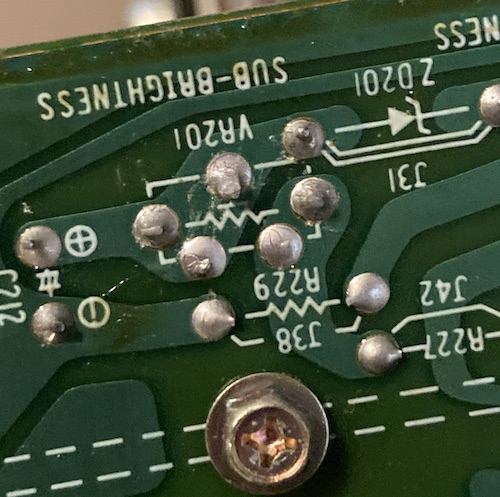
Sub-brightness, as you might have guessed from the name, sets the “base level” of brightness that the set can provide. I conceptualized it as sort of a series resistor in front of the regular brightness pot. If it were open-circuit, well… then we weren’t gonna be getting any brightness at all!
If I tweaked it to the last 1/6th or so of its throw, the pot would suddenly jump to life. Anywhere else, open circuit. I spent nearly half an hour making sure I actually was seeing what I thought I was seeing.
When it was desoldered, I was able to see the number written on the back so I could order a new part. I also noticed that one of the metal crimps on the side had let loose from the fibreglass backing and was floating in space, which probably is what caused the poor contact with the resistive material. Loose crimps sink ships.
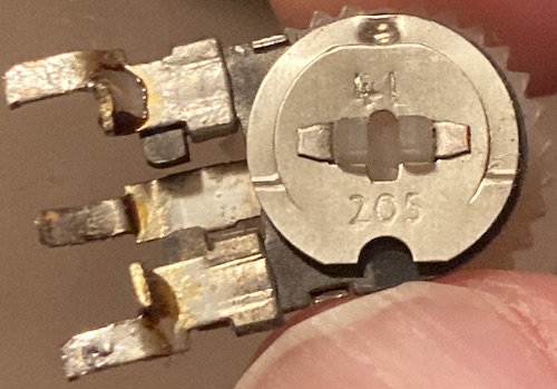
“205” implies to me that the value of this variable resistor is a 20 with five zeroes after it, or 2 million ohms. Thankfully, it turns out the little thumbwheel could be popped out of the pot, so I don’t have to match that part of it for a replacement. I set out to look for a 2MΩ variable resistor.
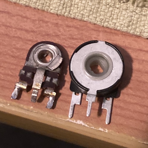
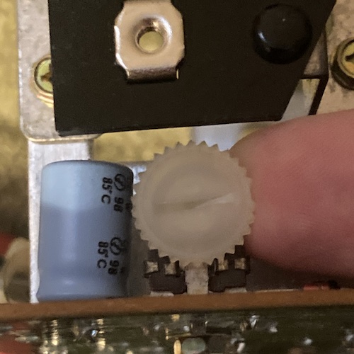
The new sub-bright pot is a CUI PTN15-C22NB20, which is significantly larger than the old one. It cost about $1.30. I had to bend the front leg backward a little bit using my pliers to make it line up with the holes on the board, but it all fit perfectly.
Unfortunately, the little thumbwheel from the old one doesn’t fit into this new one, so I had to use a flathead screwdriver to adjust it. Sketchy? Yeah, a little.
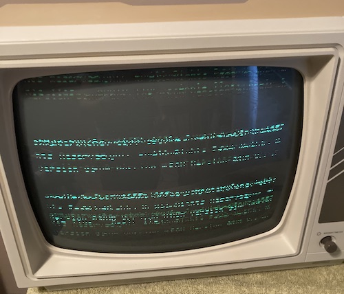
At first, I set the sub-bright pot to about 3/4, which I assumed would be 1.5MΩ. Then I turned on the set. Nothing seemed to have happened, and after a little while of knob-twiddling I decided that the sub-bright is probably out of whack. I turned it to 1/4 instead, and immediately got some garbage on the screen:
Unlike other sets that I’ve owned, this set requires you to manually manipulate the horizontal hold. That’s what the big coil up above adjusts. That’s pretty cheap-assed, but I’m sure NEC had their reasons.
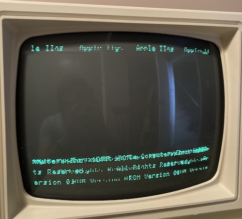
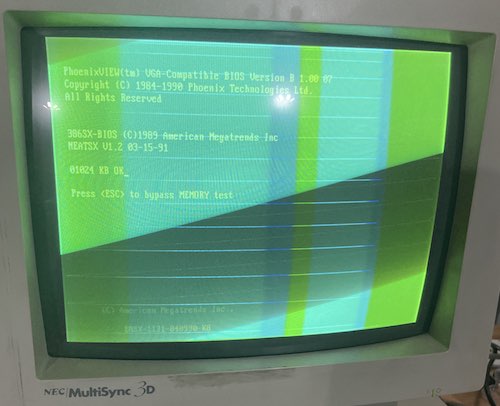
Either way, I slowly wound the coil around and then met some resistance. I pushed through that resistance, got a momentary fright when the raster became all-green with retrace lines, and then pushed through that… to legible video.
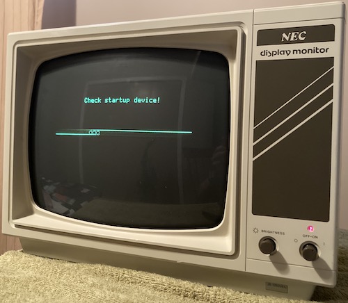
Ooh yeah, now we got some actual video. I decided to lift up the display, move the screen-protecting towel aside, and slide the IIe in underneath it. It looks a little out of sorts with the Apple IIe, even a non-platinum one – it’s definitely meant for a II+.
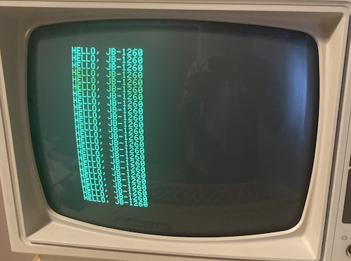
Again, I had to fight with the horizontal hold. Moving it, or maybe the slightly different signal coming out of the IIe, produced a pretty creepy green raster blob that looked folded-over. I struggled through it, and bam – this one is legible (if a little narrow?) too.
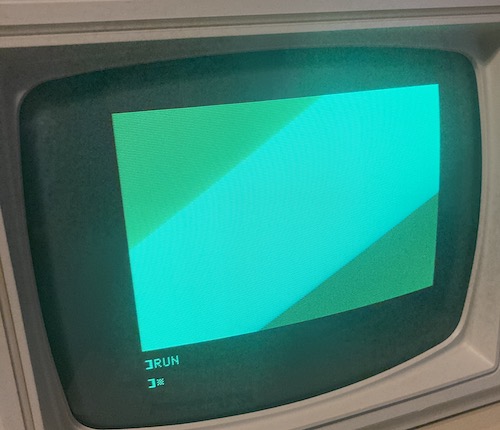
I instructed BASIC to put up a big chunk of bright (COLOR=15) low-rez graphics and adjusted the sub-bright pot. First, I set the front panel brightness to mid-point and then tweaked the sub-bright until it looked okay.
Final Adjustments
To adjust the sub-brightness to its proper level, I put the brightness knob to about halfway. Then I turned the sub-brightness control until it looked good. Now the main brightness knob had a meaningful and useful range.
I noticed while I was exercising the set that the brightness would sometimes flicker a little bit, and if I gently bonked on the top of the set it would change quite a bit or even cut out momentarily. Through tactical bonking and wiggling, I traced this problem to the front brightness pot, which got a big drink of Deoxit. Don’t bust it out until the set works: this stuff’s expensive!
Conclusion
So what’s the moral of the story on this repair? If there is one, it’s “don’t skip the basics.” I spent a lot of time assuming that the set must have some exotic failure like a horizontal output transistor, when I should have started with potentiometers, something I know breaks all the time. Still, the nice thing about a set this simple is that there are maybe like 60 parts on it, tops, and you can check each and every one of them.
There’s no hiding it: I am very glad to have this set working again. Although I certainly don’t need another monochrome long-persistence green monitor lying around the house, especially one with an annoying horizontal hold setting, this one has style. Fixing it up kept me out of trouble for a couple of weeks. And you can never regret buying a cheap CRT.
Thank you very much to both CJ and Tr3vor42532 for all their help with diagnosing and fixing the set. I learned a lot from you once again, which will help me with the next terrible NEC monitor that I bring home.
Uh-oh.
Repair Summary
| Fault | Remedy | Caveats |
|---|---|---|
| No picture whatsoever | Replace damaged sub-brightness variable resistor at VR201 | |
| Glitchy brightness when bonked | De-oxit front brightness pot |
-
The PC-6042, released alongside, was the colour monitor for the PC-6001, based on the JC-1201M. ↩