Dick Smith's Wizzard-ry 8 (Bit)
Tags: console clone vtech dick-smith-creativision-wizzard homemade-hardware derivavision
Sure, I’ve cloned TI TMS99xx-based systems before. There’s the ColecoVision and the Sega SG-1000. But those were all Z80s, and it’s important to diversify my interests a little bit. Luckily, VTech released a little 6502-based system called the CreatiVision, and let the schematics get out.
As always, we don’t do things because they are easy, we do things because we thought they would be easy.
What is the CreatiVision?
The simplest explanation is that the CreatiVision is a video game console. It was developed by VTech, and released under tons of other names worldwide, in no particular order:
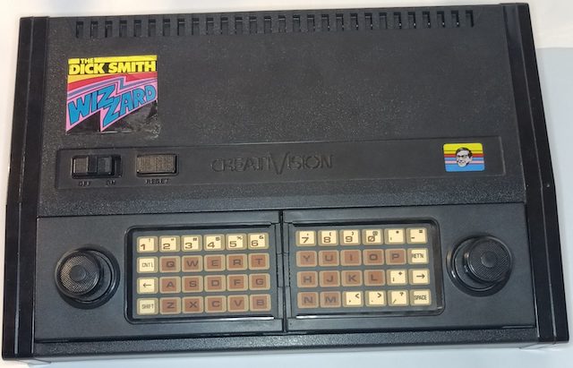
- Dick Smith Wizzard;
- VTech Funvision;
- Hanimex Rameses;
- Educat-2002;
- Telefunken CreatiVision
These are all PAL systems, but there was an NTSC release in Japan as well, as the Cheryco CreatiVision, and a test NTSC US release that does not appear to have a known distributor. There was also an announced French prototype, deemed the VZ-2000, which appears to never have been released.
There were also some divergent branches on the family tree. VTech themselves turned it into the Laser 2001, Salora sold it as the Salora Manager in Finland, and it seems like there may even be a Sanyo variant kicking around somewhere out there.
Salora, Dick Smith, and VTech had teamed up to offer badge-engineered systems before, with Oceania’s beloved VTech Laser 200. That in itself is a pretty interesting computer, and I hope to get to one of those eventually, but it is totally unrelated to the CreatiVision.
Later on, they released a CreatiVision mk2, which has some internal modifications. To me, it seems to mostly be decoding changes in order to support a Z80-based ColecoVision game adapter.
You’ll see the name mentioned frequently throughout this article. For now, remember that Dick Smith was an Australian/New Zealander chain of electronics stores, seemingly equivalent to an Oceanic Fry’s Electronics.
I am eliding a lot of the fascinating history of the CreatiVision in order to get to the cloning faster. If I’m missing something or have some facts wrong, please let me know. Thank you to MADrigal from the CreatiVemu forums for correcting some of the historical errors here.
The Control Scheme
Anyway, as I have implied a few times here, the controller “paddles” double as gamepads. Like the ColecoVision, they are meant to be operated in a sort of portrait orientation, with a joystick and two fire buttons. There’s also a membrane keypad on each paddle.
And if you put those paddles back into the case, they combine to turn into a membrane keyboard. That’s right, the keypad is complex enough on each to form an entire keyboard for BASIC programming and other computer shenanigans. Extremely cool – split keyboards are not just a modern mechanical keyboard fad after all.
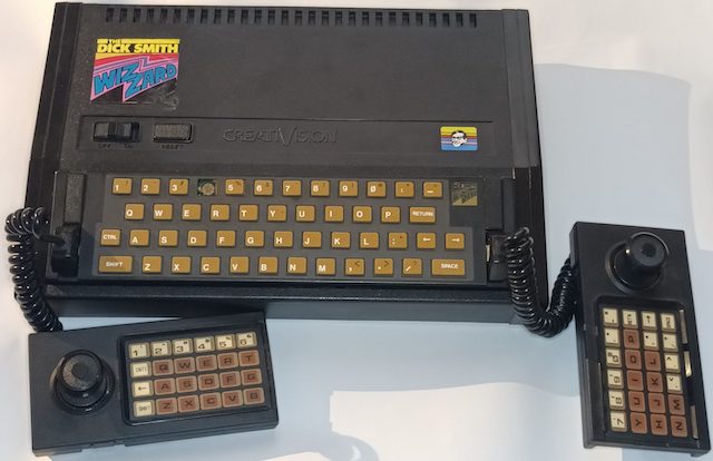
Of course, they also sold an optional standalone keyboard accessory, which seems like the ideal way to use this machine.
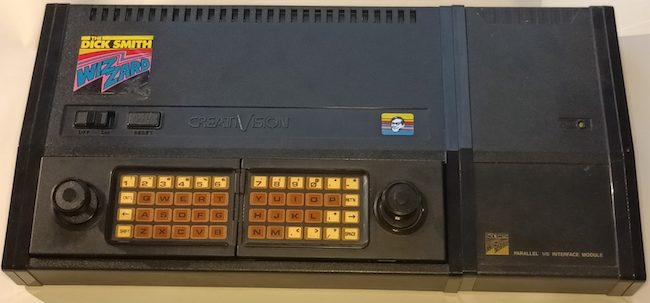
On the side is a cartridge slot, which you can install a bunch of peripherals into. The CreatiVision offered parallel-port expansions, memory expansions, and even a floppy drive. There’s also a connector for a cassette tape deck, for saving and loading BASIC programs.
What’s interesting about the hardware?
Well, to me, it’s a novel machine, one that never reached North America in great numbers. I’ve certainly never seen a CreatiVision in person before. And with the keyboard, it’s a computer-like console, which means that it could run general-purpose programs like BASIC. That’s pretty much the reason why I embarked upon the SG-1000 clone, so that’s enough justification for me on its own.
Technically, I figured that the clone would be relatively simple. Like I said earlier, I have already made several TMS9918A-based systems, and the CreatiVision schematics are public.
However, those previous systems were all Z80, and this gave me a chance to cross the railroad tracks and play with the bad MOS kids from the other part of town. My only prior experience with the 6502 came from writing some Apple II assembly programs, and I certainly have never wired up its bizarre “Φ2” machine cycle stuff for decoding.
What’s good to play on it?
Good question! I had absolutely no idea, so I went to YouTube. For whatever reason – likely cultural imperialism or Australia’s well-documented video-camera-killing-rays – there wasn’t much footage of the system’s games. Highretrogamelord, of course, has a playlist of games. A lot of them appear to be clones of popular arcade games, which is okay in my book. Many games, like Auto Chase, offer some smooth scrolling, which is definitely hard to do on the TMS9918, and indicates some competent programmers at play.
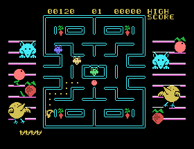
It was harder to figure out from the videos if any of them were good, so I decided to try Crazy Chicky, a Pac-Man-alike, in MAME.
Not bad. Okay, let’s get started.
Why a clone?
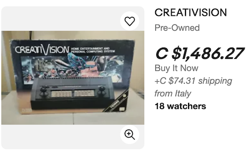
Primarily, I didn’t have one of these, and I doubted I would be able to get one. Canada never got a release, as far as I could tell, and eBay prices were – as one expects – silly.
Sure, I could have hunted for awhile to find a working one, but the hardware isn’t the best quality. Being a cut-rate machine assembled in a low-end factory, the original Creativision motherboard had a lot of flaws: bad vias, poor-quality sockets, a flimsy board that breaks traces, a flimsy power supply, and case screws that short out data lines if you tighten them too much. Cheshire was dealing with a large number of these problems, which is part of why he asked me to take a look at it.
He’d also been dealing with the controllers themselves: together, they turn into a sort of split keyboard and otherwise are an enormous membrane. That membrane was wearing out after decades of hand-borne contaminants, and so his controller PCB reproduction was born.
As a bonus, I’m not at all the first person to be dumb enough to try this. Someone else already cloned the Funvision on a breadboard using the same schematics and a CMOS 65c02. Looks like it went really well in that case, and can’t possibly go wrong for me, right?
6502 Decoding
I had assumed that the 6502 was sort of similar to the Z80. On the Z80, in order to decode parts on the board, you just hook them to the , , , etc pins and then the address lines. The Z80 lights these lines up when it’s time to reach out to external devices.
On the 6502, it wasn’t quite as obvious to me how this was supposed to work. Although there was a read/write pin, there wasn’t anything that was clear to me as being “an access to external devices.” Instead, the 6502 had a bunch of weird pins, named things like Φ0, Φ1, and Φ2. What’s going on with that?
To figure it out, I did some research. Thankfully, it was pretty easy to find out the answer, because the 6502 was and is a very popular CPU. These phi (Φ) pins represent the machine cycle of the CPU. Φ1 and Φ2 are outputs that are derived from the input clock on Φ0: Φ2 is essentially the same (amplified) signal as the input clock, and Φ1 is the inverted form of the input clock.
On a read, Φ1 goes high when the 6502 is controlling the data bus, and external devices can read the address, read/write control pin, and the data bus that the CPU is driving. Φ2 goes high when an external device is allowed to control the data bus. They’re never high at the same time, which means that Φ1 can be used to select active-low peripherals like the VDP as it’s the logical inverse of Φ2.
I’m sure it’s a little more complicated than that once you get really down into the weeds of timing, or implement some kind of ridiculous DMA system while the 6502 is “busy,” but the CreatiVision doesn’t seem to do anything super ambitious in this field so I don’t need to know it yet.
The CreatiVision makes decoding a little more bizarre than on most cartridge-based systems, as even access to the onboard BIOS ROM is controlled by the cartridge. All three bank select signals (, , and ) are passed to the cartridge, and the cartridge is expected to trigger the onboard BIOS select pin , usually by shorting it to .
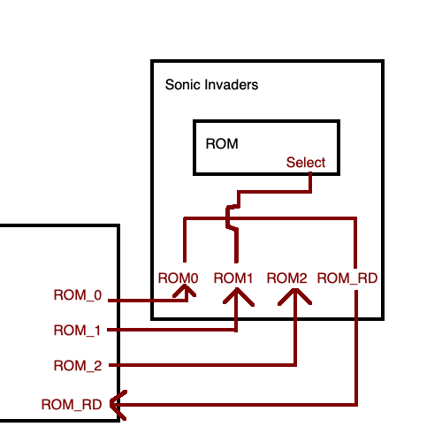
I’m not sure if any software actually takes advantage of this to remap or disable the BIOS decoding at runtime in order to offer more memory space for game ROMs – Cheshire’s own MegaCart just hardwires it – but the capability is there.
This is likely here so that an expansion device could provide a substitute BIOS to the system. I’m not entirely sure why you’d do that, versus just putting it on the regular autobooting ROM, but the capability is provided regardless.
Constructing the clone
Laying out the clone board from the schematics was pretty easy. There was one seemingly ambiguous thing that I made a sleep-deprived error on transcribing to KiCad, but we’ll talk about that a bit later.
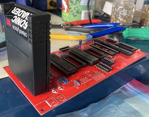
I asked Cheshire if he had something to test with, and he just smiled and sent me a Sonic Invaders cartridge. I’m pretty sure that’s how the song goes.
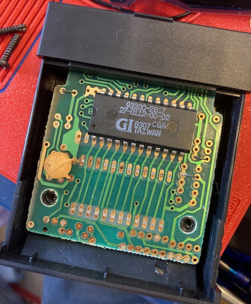
This cartridge sure looks a lot like the Intellivision ones, right down to the weird half-door on the back. Does nobody have original ideas for cartridge shells these days?
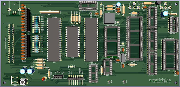
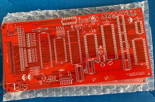
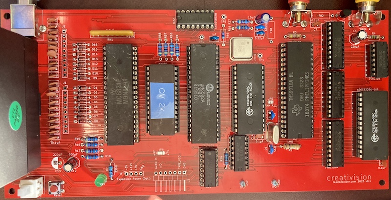
Now that I had enough ducks in a row, I sent away for the clone Creativision board, which is (I think) my widest one yet, at nearly 220mm wide. I feel like I could have taken better advantage of the space available, but I already ran into a nightmare trying to route the cartridge lines through all the diodes and resistors for the keyboard/controller connectors. The reason why it’s so long and slim is mostly because it’s easy to route. Luckily, it is also conveniently easy to stick a keyboard in a case with it.
It took a really long time after the boards showed up for the 6821 PIA to arrive from AliExpress. When it did, it was only at this point that I realized that Western Design Center is still making new 6821s (in both CMOS and NMOS!) Somehow, I also kept running out of common consumables, like 40-pin sockets and 33pF load capacitors.
All version-one systems are gonna be a little awkward, and the cartridge slot in this one definitely qualifies. If I can find a part for it, I think I will change this to a right-angle slot, both to make it look sleeker, and to support installing sidecars like the original system had. Of course, the slot for the original system is on the other end of the board…
I ran into a bit of a snag with the BIOS ROM. Like the Leako and Soggy, I had laid it out to use a 27c256 EPROM. However, I was starting to run out of those after some recent arcade shenanigans, and ended up having to spend an afternoon erasing some before I could actually program a BIOS ROM and be able to try the system. I could have used a 27c64, which I had dozens of, but it would have involved cutting the 27C64’s pin free from the ground pour it was stuck in. For version 2, I have changed this to use a jumper so that this pin is high by default, which won’t affect a 27C256 in this position, as the 2K Creativision BIOS ROM will be duplicated throughout the memory space anyway.
First Run
It didn’t work! And not even in the fun, sorta-works way. I mean the LED flickered dimly once and then I didn’t have any power at the test connectors - just 0.15V. I pulled the AliExpress parts out of their sockets to make sure they weren’t shorted, but to no avail. The series voltmeter on the USB port reported zero amps of draw, so it seemed like the power supply of the board… wasn’t supplying power.
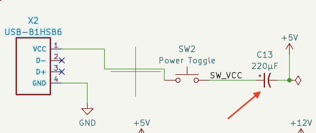
I should have noticed this earlier, but it took showing a screenshot in Discord to realize what was the problem. A cap in series blocks DC and not AC, which is sort of the opposite of what I wanted. ZephyrZ80 and YesterGearPC pointed it out. Thank you!
Once this was resolved, the system would power up, establish a blank raster, but with solid NTSC 480i sync (according to my long-suffering PVM.) I knew that I had to insert a cartridge in order for the system to work, so I did so, but there was no difference in function. It seemed that the game wasn’t being run properly.
Suspecting a decode problem, I popped in some test hooks and went to my trusty logic probe. The BIOS ROM was selected briefly on reset and then never again.
As far as I could tell, the clock was working, there was activity on the address bus, and the data bus, up to a point. After a few seconds of execution, D0 and D1 become always low. Same with the read/write pin. That’s odd, I thought. Those should be changing the most.
For its part, the TMS9918A seemed to be happily off in its corner, taking care of its RAM, even though no writes or reads were happening to it. What a trooper.
Just to make sure it wasn’t the CPU, I swapped in another beaten-up UM6502A from AliExpress, and its function seemed identical. I checked the pinout to make sure there wasn’t some subtle disagreement about data bus pinout between the UMC part and the MOS part, and there wasn’t.
After some grumbling and staring at KiCad, I realized that I had misread the original schematic.
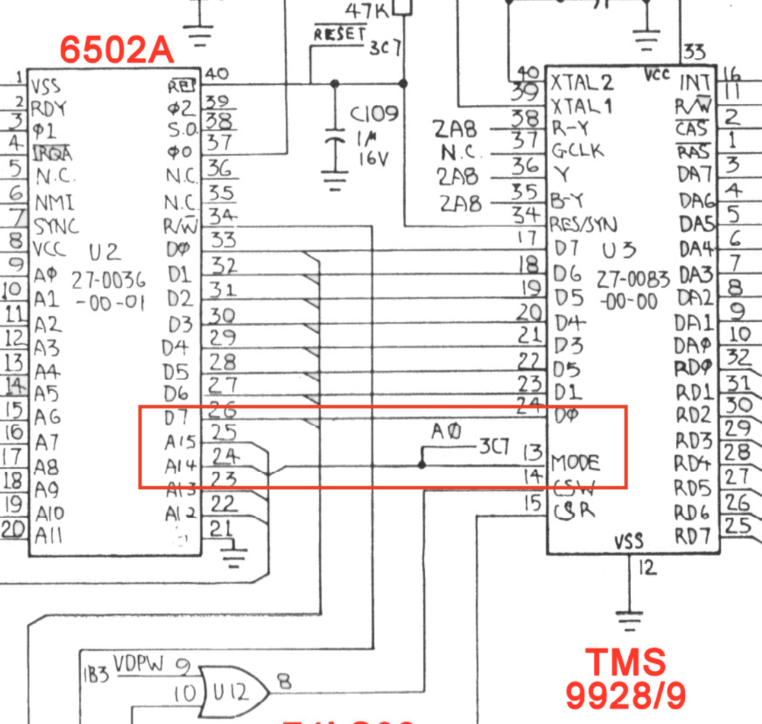
This line wasn’t coming off of A14 to the MODE pin of the TMS99181; it was coming off the address bus, and was actually connecting to A0. I’m not sure exactly what that meant for the correctness of the program, but I would assume that A14 was always low during writes or reads to the VDP, and so this pin would never be toggled high during runtime. Which could cause some problems, especially if you wanted to, say, tell the TMS9918 what address to write to. Yeah, you don’t need that at all.
After some studious pin counting, I cut the errant trace and wired MODE to A0. Now on the logic probe, I could see that D0 didn’t get into that degenerate state from before. It kept happily oscillating. Good enough for now… let’s try it on a TV.
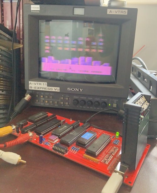
Due to the endless churn of my shop, the setup wasn’t ideal, but I was able to run this on my test PVM. The game runs!!!
Unfortunately, the image was legible but had lots of luminance blur. This might be because I had run out of ferrite beads and hadn’t loaded any for the video and sound, or because this particular TMS9918 was sick, or because the dying PVM has chosen to die in a whole new way. Still, this is a triumph. We now had a Creativision clone that works well enough to play Sonic Invaders.
The ferrites did eventually show up, so I decided to plug them in. I wasn’t exactly clear on which video characteristics I was trying to eliminate with a ferrite, but I was hoping to at least get rid of the blur that I had somehow added between the Soggy and the Derivavision v1.
With the ferrites installed, the video quality looks quite good, even on the crappy USB capture device that I have used on videos in the past. This seems like it’s the nicest output I’ve ever gotten out of one of my clones, and maybe I should think about backporting this change to them as well. Check out the detail on the windows in the background!
Of course, since I don’t have a controller hooked up, this is the automated “attract mode” from the game, playing itself. This player is not especially great at Sonic Invaders.
Conclusion
I’m very happy to have gotten this clone to work, although without controllers it’s just not very much fun yet. Through this project, I learned a lot about the 6502, a medium amount about composite video, and a little bit about life.
You can download the KiCad files for the DerivaVision here on GitHub. I will do a formal “release” with Gerbers once the controller interface is ready to go.
Next Steps
You wouldn’t think installing a controller port would be a difficult task, but the VTech machine has a trick up its sleeve. Those slick keyboard/dual controller input devices are built of a complicated passive matrix, similar to the ColecoVision. Speaking to them so that we can actually play Sonic Invaders is going to require a lot of monotonous grunt work, and just a little bit of ingenuity. Some joystick buttons are implemented by shorting more than two pins together at the same time!
In the next part of this series, I’ll be building a clone keyboard/controller interface that will plug into the headers on the existing v1 board. This will be pretty rudimentary: just enough to play Sonic Invaders and maybe a handful of other cartridge games that don’t take advantage of the keyboard.
After that, I think I have a better plan: replacing the 6821 with a Raspberry Pi Pico2, and using that Pico to handle a PS/2 keyboard and SNES control pads. Although it will be a lot of work to reverse-engineer the 6821, especially if the games/BIOS hammer the ports quickly, the end result will be an integrated, single-board Derivavision console that plays games without needing any sub-boards or expensive custom keyboards.
-
The
MODEpin is used during CPU-VDP transfers to signal what part of a command is happening. For instance, theMODEpin is held high during a write to the VDP in order to tell it that we’re sending addresses to it, and then low to send data to it. The reason why the concept of this pin seemed confusing to me is because this is hidden during software development. On the SG-1000, I wrote to e.g. $80 for data, and $81 for addresses – that’s where A0 comes in. ↩ -
I am pretty sure something smaller like a PIC would also be able to handle this case medium-well, but an entire Pico development board is pretty close to the same price, has the benefit of the PIO acceleration, and I already have a handful lying around. ↩