Floppy adapter board works for the PC98!
Tags: computer nec pc98 pc9821 pc9821ap2 floppy compile gotek retrochallenge retrochallenge-september-2018 homemade-hardware
After I designed the first version of my PC88 floppy board, I thought it would be fun to put one together for the PC98 as well. Why do I need an adapter for a computer that already has 3.5” floppy drives? The PC9821AP2 I own has a 26-pin floppy drive connector, like a mid-90s laptop, and most standard IBM PC style floppy drives have 34.
What’s more, my PC98 doesn’t have a standard Molex 4-pin power connector for floppies; the 26-pin cable carries 5V power as well.
The Board
There are a few schematics out there, but I shouldn’t have gone all the way to the Japanese internet for them. It turns out the FlashFloppy wiki had the schematic the whole time:
(26-pin) -> (34-pin + power)
Power   1 -> 5V
Index   2 -> 8
MotorA  4 -> 10
Density 6 -> 2 (see note below)
DS1     7 -> 12
Ready   8 -> 34
MotorB  10 -> 16
Dir     12 -> 18
Step    14 -> 20
Ground  15 -> GND
WData   16 -> 22
WriteE  18 -> 24
Track0  20 -> 26
WriteP  22 -> 28
RData   24 -> 30
Side    26 -> 32
I’m not sure about the “6 -> 2” part of this; another diagram I found said that pin 6 on the PC98 is DISK_CHANGE, which is pin 33 on the 3.5” floppy. Pin 2 on the 34-pin is DENSITY; from what little I understand of floppy drives, it makes no sense to connect these two. I ended up routing 6 -> 33 correspondingly, though this might be the cause of a strange problem I seem to be having (more on this later).
Note also that I haven’t tried two of the same board in one machine, since I don’t have a dual-drive 26-pin ribbon cable.
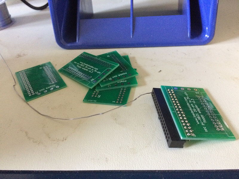
I went through a few revisions of this board - my most boneheaded mistake was omitting the power connector entirely.
- v1.0: Cancelled because it had a power connector (d’oh) before it even went to fab. It would have been 100% fine.
- v1.1: No power connector, because I somehow got it into my head that the floppy drive would get power from somewhere else, even though I had seen pictures of an existing PC98 adapter that had a Molex connector on the board. Also extremely enormous, because I didn’t take the time to route my traces very well after having to rework the board to remove the Molex.
- v1.2: Has a Molex connector, but due to a bad footprint, the holes were too small for the part I ended up using. I still made it work (see below.)
- v1.3: Still in the mail. Has a Molex connector with the correct footprint from Digi-Key, is a little teeny tiny bit smaller than v1.2.
It’s a learning experience. I’m currently thinking about ways to tile my bathroom with the leftover PCBs.
Assembling the Board
Since the Molex connector didn’t fit, I figured I’d just cut one of the very hard-to-find (in my city) floppy Molex-to-Berg adapters I had picked up for the PC88 and solder it on. Unfortunately, I didn’t realize the floppy power connector was on the other side of the board and the cables couldn’t reach, plus it looked bad. Hopefully some other project needs a very short length of Berg wiring in the future.
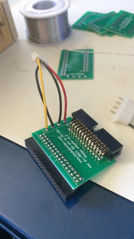
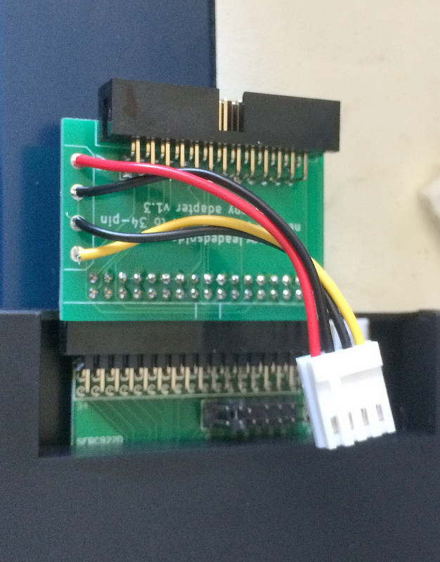
In the interest of time, I ended up just grabbing two male-to-female jumper cables out of my pile and soldering them on. Looks bad, works okay.
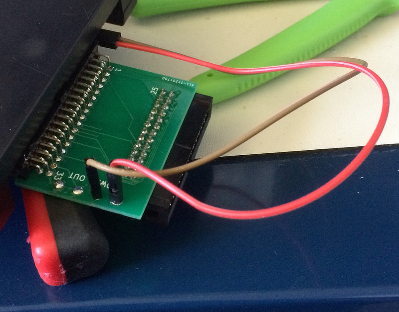
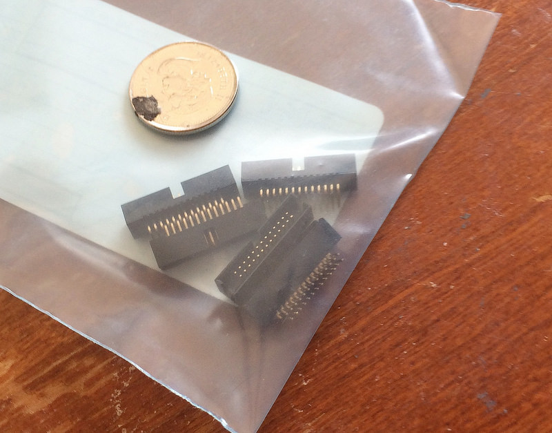
I also ordered a 26-pin header in the wrong pitch. Apparently you can get them in “very small.” Standard Canadian quarter for scale.
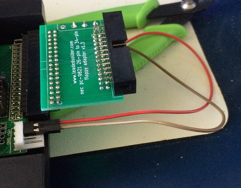
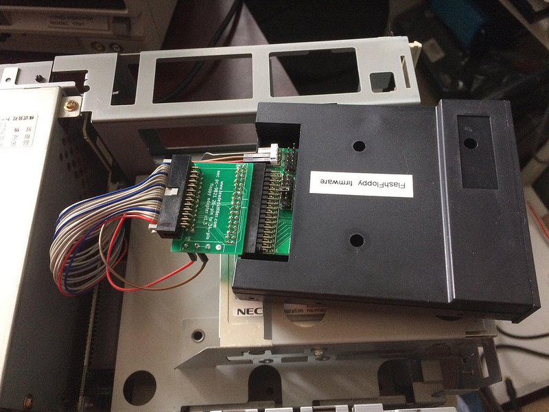
Eventually, everything worked out and I got a board that plugged into the Gotek in all the necessary places.
Preparing the Gotek
I’ve gone over this a few times already, but flashing the Gotek is basically this process:
Open the Gotek
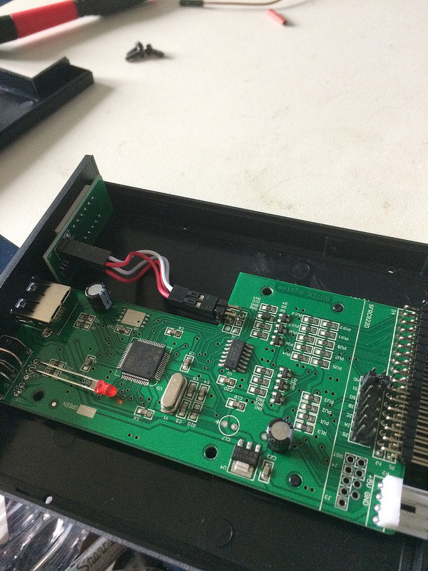
Solder on headers, then run jumper wires
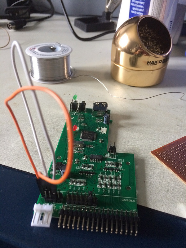
You need jumper wires because one of the connections is diagonal. More info in this great guide.
Flash firmware
I used FlashFloppy 0.9.28a and the male-male USB cable with a Windows copy of DFUse.
Connecting to the PC98
Plugging it in isn’t too hard, assuming I soldered the connectors on straight. Pin 1 is red, and delivers five volts, so don’t get it backwards.
I also swapped the drive-select jumper on the Gotek itself from S1, which it comes stock as, to S0. There’s no ‘twist’ in the cable for drive select like there would be on an IBM PC.
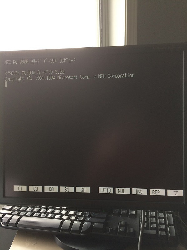
Let’s fire this thing up first without a USB stick. It comes alive, and then almost immediately goes to the “insert system disk” screen. This is a great sign, because I’ve seen with other PC98s running HxC or Gotek that it just lags for a long time before getting you there. This means I can still quickly boot off my hard drive (whenever it arrives from EMS) with the Gotek installed.

I pulled a fresh USB flash drive out of its package (like the baller I am), and then dumped an FDI disk image on it. The PC98 booted off the disk, and went to a DOS boot screen, and then… seemed to hang there.
I’m not sure what happened, but after a long time I decided to tap the change disk button on the front of the Gotek. This made the computer wake up and proceed. It might be something to do with floppy sense (the DISK_CHANGE problem I mentioned above) or some hack that was done on this game when it was moved into its own disk image. I’ll try this with more disk images later.
Playing video games
I don’t necessarily own a license to Compile’s Marvel Putt Golf, but if they want to come and get some money from me, they’re welcome to it. In exchange for fanboy fawning.

According to the place where I got it, this was part of a “DiscStation DS98 #04” collection. I’m guessing it was a freeware game or tiny demo done by bored programmers between big jobs.
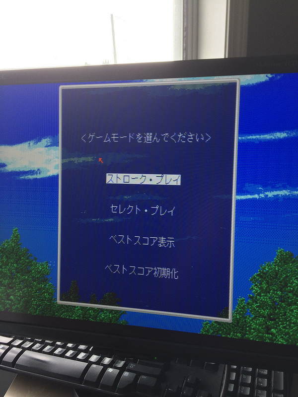
I’m assuming this is a main menu. When I hit return, it took me first to a (non-keyboard-friendly) name entry screen, and then to choose whether I wanted to play the front nine or back nine of a course. Let’s start with something simple…
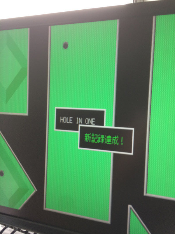
Maybe too simple. That’s as good a place to leave this entry as any.
I’m expecting my next update to be about the colour video for the PC88, as the adapter board I designed to avoid having to chop and splice DIN cables is nearly here - if you believe UPS’s lies.
Downloads
You can download the Gerber files for this adapter from the PC-9821 floppy adapter project GitHub repo’s “releases” page. The BOM is listed on the README in the front page.