PC-8801mkII floppy adapter board
Tags: computer nec pc88 pc8801mkii floppy gotek cleaning retrochallenge retrochallenge-september-2018 homemade-hardware
I wanted to get a Gotek working on my PC88, and after seeing that there were a lot of Japanese hobbyists who had managed to get an HxC floppy emulator working, decided it must be possible - even if not simple.
This is a fairly long read, so get yourself settled in.
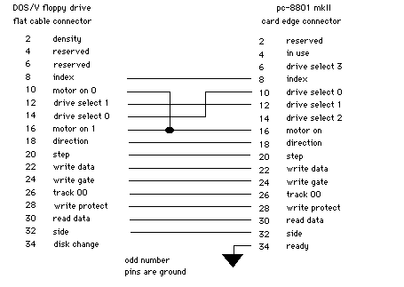
My first stop was to Koichi Nishida’s website, not least because of the quality of his writeups but because he managed to build an adapter for his own mkII. There, I found this fantastic schematic:
Update: This schematic works great for a single drive in the machine, but I had trouble when trying to use more than one floppy drive at a time.
Update 2: When you’re using a Gotek instead of an IBM PC 3.5” floppy drive, you should be using Shugart wiring instead, such as described in this schematic:
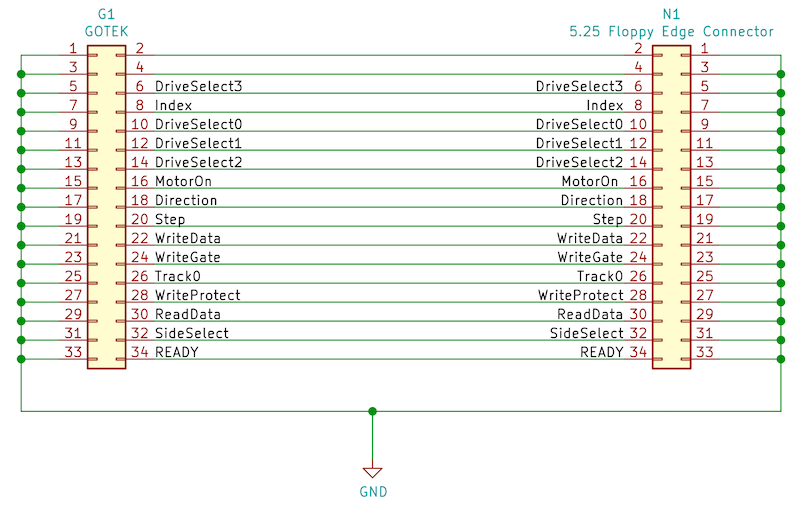
There are some generic 5.25” to 3.5” floppy adapters out there (common in the early 90s) that already serve this purpose.
The rest of this article remains unchanged, so be careful.
Chairman of the Board
I designed the board in KiCad, ordered away to Oshpark, and it arrived about three weeks later, just in time for the new run of RetroChallenge. There were a few firsts on this project: first time figuring out how to make my own custom footprint for the edge connector, and first time sending a board to Osh that did more than just have a resistor and an LED on it.
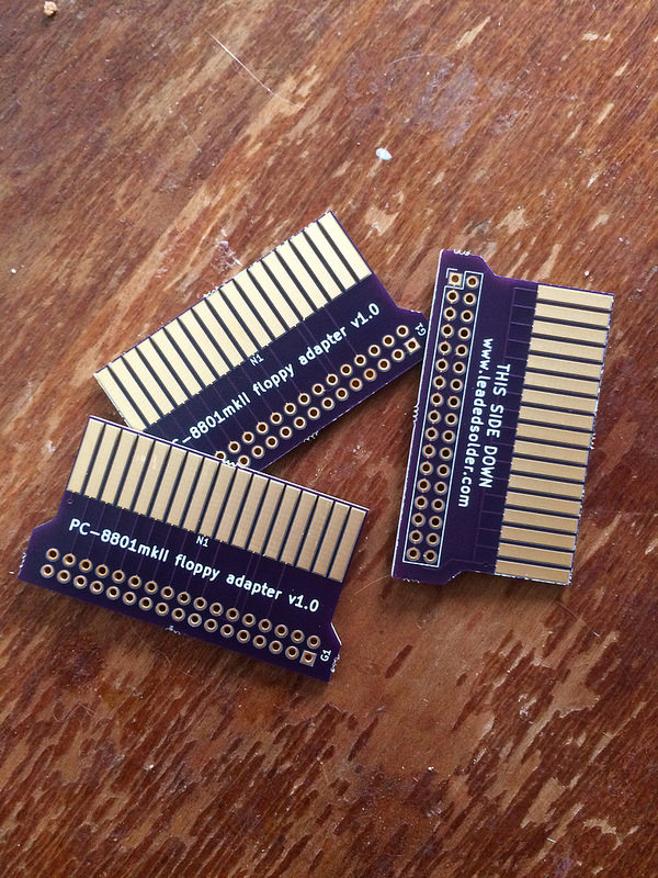
I was most worried about whether or not the edge connector would fit, but it does seem to fit alright. The board could have been a little thinner, since it fits really tightly into the ribbon cable connector, tighter than the original one did. I don’t want it to bend any pins. The width was a little narrow for a PC ribbon-cable connector, but turned out to be just right for the 88.
Never Stop Bodge-lieving
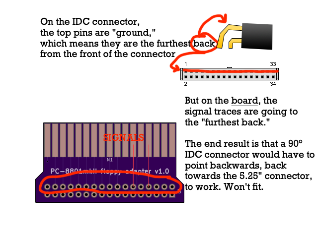
Unfortunately for me, because I was pretty inexperienced with KiCad and didn’t know how to add third-party footprints yet, my two-row pin header was actually backwards from how a real floppy drive connector would fit. You see, on a 90-degree IDC connector, the signal pins are on the “bottom” (i.e. furthest from the edge) and the ground pins are on the “top,” but I got this backwards.
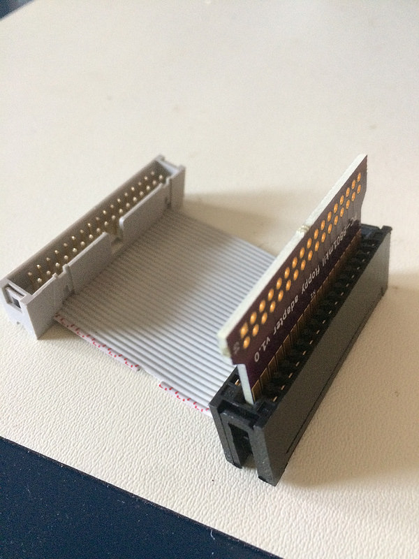
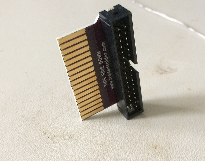
This meant I couldn’t use the 90-degree IDC connectors I had ordered, so I had to do another emergency order to Digi-Key in order to get a vertical IDC male connector, and used a standard floppy cable to join from the board to the Gotek. I’ve since revised the board to fix this, but obviously with three boards and two floppy disks I probably will never have a reason to run another one of these boards off until I get a mkIISR.
Once the bodge connector arrived, it was a pretty easy soldering job. The weird 45 degree angle at the base of my “Hakko” clone fume extractor is surprisingly good at keeping stuff like this level and tight during soldering.
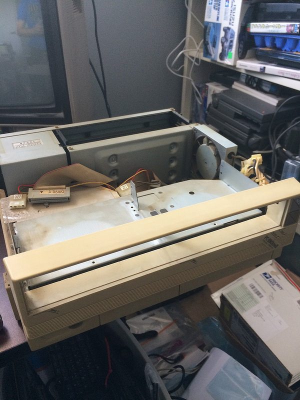
Clearing Room
It’s hard to get the floppy drive power and data cables out without removing the floppy drives themselves, so that’s what I did next. Delving into the filthy machine, I encountered some cammed-out screws. It seems a previous owner had been in this machine and done an inexpert job of removing a basic Phillips head screw from multiple locations.
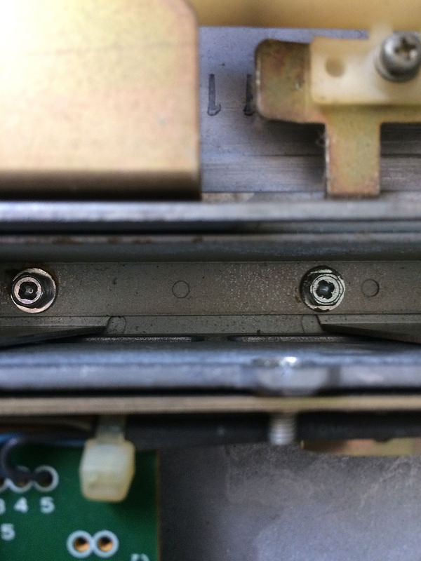
Even the ones on the side, which are relatively easy to access, were badly damaged:
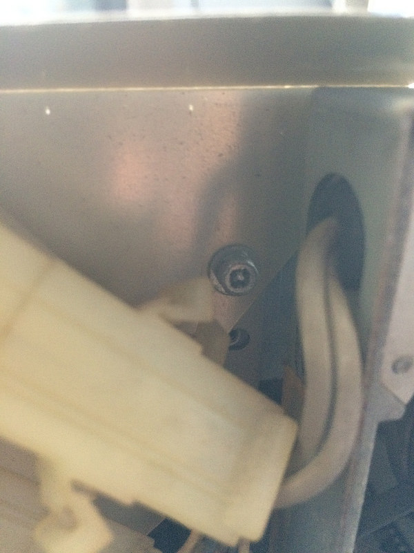
After an unnecessary trip to the hardware store to pick up a 7/32” nut driver, it turned out that I could just unbolt the floppy drives from the side using a 7/32” socket, and remove the main mounting screws with an even bigger Phillips, a lot of downward pressure and some power cursing. I didn’t even have to break out my Neji-saurus.
The 5.25 drives were liberated from the machine, although a bit of interior case plastic was damaged in the process. Thankfully, nobody will ever know unless I tell them, for example in this blog post.
I celebrated my victory by first meticulously labelling everything for future generations, and then taking the machine out to my driveway to blow it off with my garage air compressor. A worrying amount of grime remained even after the cloud of whatever it was in this machine floated off into the ether.
Don’t Flash That Floppy
I used the open-source FlashFloppy firmware in a previous entry in order to make a Gotek work on my Amiga 2500. It’s pretty easy to install: solder on a header, jump a couple pins, and use a DFU programmer to flash it with an appropriate bootloader.
FlashFloppy again was pretty easy to put on, but then I read the website documentation to find out that FlashFloppy did not officially support the PC88. Rather than run the risk of adding yet another variable to something that was already looking difficult to solve, I bought an HxC Gotek license for €10 (very well spent, in my opinion) and am running HxC’s firmware, which does officially support the PC88 (although D88 images need to be converted to the rawer HFE format, using his tools, to work).
I hope in the future FlashFloppy will support D88 for the PC88, as it already supports D88 for the PC98. Hopefully, I can contribute to the project soon.
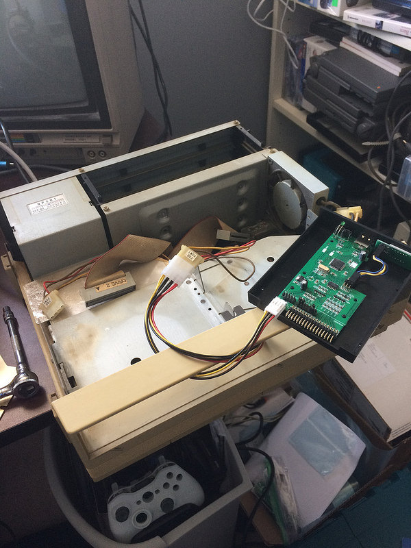
Power Up
The next step was to run power to the Gotek. 5.25” floppies usually use a Molex 8981-style 4-pin power connector, like you used to see on ATA hard drives, but 3.5” floppy drives usually use a smaller 4-pin connector, often called a “Berg” or “LP4.” Since the IBM PC market already went through a transition from 5.25” to 3.5” floppies, the computer aftermarket has solved this problem, although by the year 2018 these adapter cables are starting to get hard to find again.
After striking out at the few remaining computer parts stores near me, I headed across town to the “weird” computer parts store. Somehow, it’s still in business, and had a drawer full of these cables as well as a healthy stack of floppy ribbon cables. If only they had blank 5.25” floppies, I could have gotten my entire eBay wishlist taken care of in one shot.
When you’re doing something like this, it’s a good idea to get a multimeter and check to make sure that the computer actually is outputting 5V on the pin you expect. I’ve heard independently that some NECs (mostly PC98s) are backwards, and the Gotek probably doesn’t appreciate having 12V shoved into it. As with the monochrome video cable, a little double-checking is a lot cheaper than doing more repairs.
Everything checked out fine - the red wire did carry 5V, and it lined up with where the Gotek expected it. However, the PC88’s Molex power connector only populated one of the ground pins, not both as the ‘spec’ calls for. This was fine since the Gotek connects both ground pins together, so as long as either one is touched we’re good to go.
After connecting the $4 Molex-to-floppy-power Y-cable, the drive came alive. Sort of.
You Don’t Need Eyes To See Where We’re Going
One thing I was extremely concerned about was that the 7-segment LED screen on the front of the Gotek was not working. It should have displayed HxC and then Ldr, but wasn’t showing anything at all.
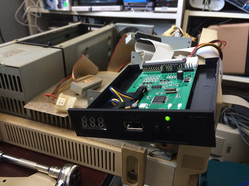
After an hour of thrashing, I determined that I had unplugged the LED display to solder onto the board and didn’t connect it back up properly. I am not a smart man.
I might put an OLED screen in this thing so I don’t have to use the HxC “indexed” mode, which is somewhat less flexible than FlashFloppy’s default mode.
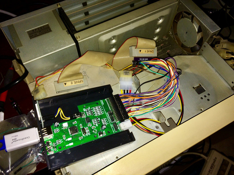
Orientation Is Critical
I spent a few hours cursing myself, getting confused, and eventually hand-rewiring the board. I’ll skip over the specifics, except to tell you that:
- It was right the way I designed the board originally,
- Something was funky with the twist in the floppy cable,
- And thankfully I buy my jumper wires in packs of 40.
Here’s the tangle of jumper wires:
As is the norm for this machine, when it works, it works with absolutely no drama or suspense. It popped into this screen so quickly after booting that I thought maybe I had broken the computer in my rewiring mania.
Reading Is Fun-damental
IT WORKS!!!!!
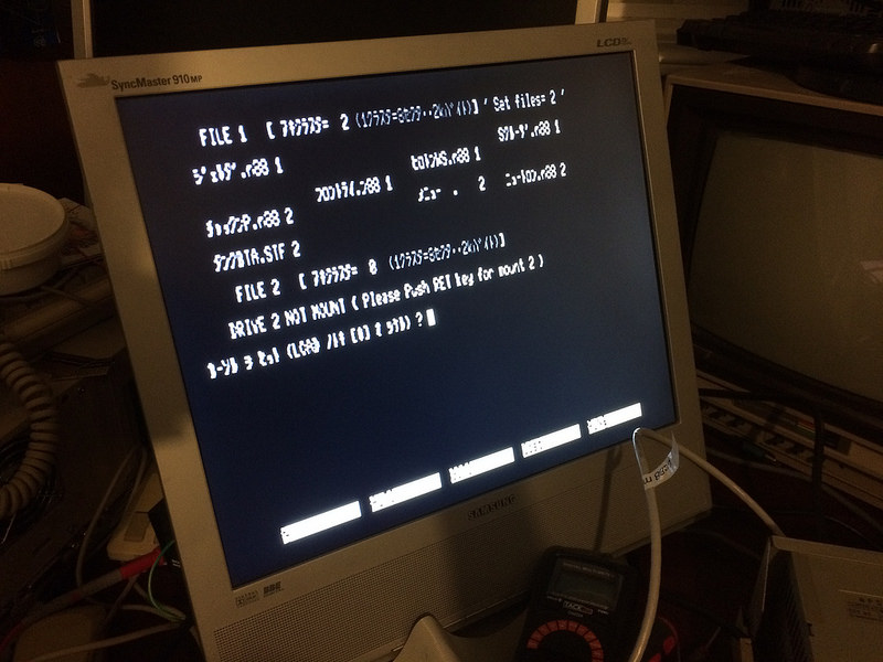
I had picked what the Neo-Kobe set had called a PC-8801mkII demo disk for my test disk, thinking it was one of the official NEC demos. What it appears to be is some crazy BASIC-based multidisk, and requires you to type the precise kanji of the name of the program you want to load.
Unfortunately, the display is too smeary and terrible for me to actually be able to tell what the characters are.
I plan to put more images on the Gotek’s USB drive soon, so I can have something else to run. Maybe there’s a game or something for small, slow children that doesn’t involve having to type accurately. It would also be nice to have a second Gotek, so I can save my game or BASIC programs.
For now, though, I plan on smugly telling everyone about the extremely obscure retrocomputer that I managed to build my own circuit board for and have it work. I’ll let you know if anyone shows any interest.
I also want to release the board so others can use it, but until the above mistakes are corrected and I’ve tested a revised version, I don’t feel good about making other people spend money and time on it. When everything seems stable, I’ll make a new post about it with a download for the KiCad info and gerbers.