The Most Useless MSX
Tags: computer msx casio pv7 repair
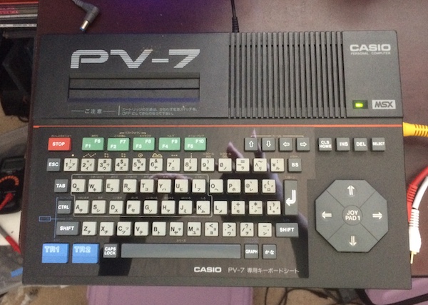
One of the more unloved MSX1s is the Casio PV-7. This poor little 8-bit computer was saddled with a crappy keyboard, only 8kB of RAM, no printer port, no built-in tape interface, and only a single cartridge slot. And that cartridge slot doesn’t even follow the MSX standard!
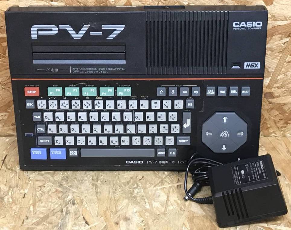
I became interested in this machine when I saw it in a video, as part of a collection of other MSXes. The tiny size and general unloved status of the computer appealed to me, and on top of that, they were pretty cheap on Yahoo! Auctions as well. I got this one for ¥2200, which was a little pricey, but it came with the 10V centre-negative power brick. Unlike a lot of other MSXes, at least the cord isn’t hardwired in there, and it could conceivably be replaced with a 110V-compliant North American 10V brick down the road so I don’t have to keep using my step-down converter with it.
Normally, I would have gone for the red model, but the pictures all make it look like sort of a depressing dried-blood colour. Definitely not pretty enough to wait longer for, or pay more money in the hopes of getting a red one.
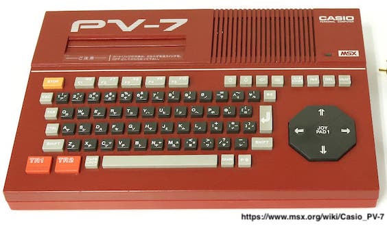
When it arrived, I gave the machine a quick look over. The keyboard is surrounded by a hard paper insert with a sticker on top, instead of a more expensive case silkscreen, to tell you what the alternate features of each key are. Unfortunately, the glue is losing its stickiness, so it’s starting to peel up a bit on the edges. I think it might be possible to borrow a friend’s vinyl cutter to make a reproduction sticker, but to do so is almost too much effort for this computer - I’ll leave it to future generations. Most of the PV-7s I’ve seen have simply lost their inserts decades ago, as with the red example up above.
Testing
I couldn’t wait to test this thing out. Like the HB-101, this PV-7 plugs into composite video, and also features a tiny little RF modulator.
I plugged the MSX into my long-suffering - and increasingly likely to be a future entry - Sony PVM and my step-down converter and flipped the switch to fire the computer up.
I got nothing. The power supply seemed to be producing voltage (14.6V unloaded from a 100V source) but the little light on the computer wouldn’t switch on when I toggled the power switch. It was sold as “energized testing” so it should at least get power…
I immediately disconnected the machine from power and started looking into it.
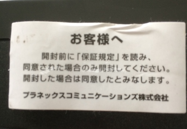
I liked that this sticker was retained by the original owner. There are a lot of characters here I can’t read yet, but Google Translate says that it is your standard warranty threat. It doesn’t say you can’t open it, just that you should read the warranty rules before you do. I’ll take my chances.
Opening the computer isn’t difficult. You just take out one screw from the underside and then work slowly around the periphery with a spudger until it pops free of the six or so clips on the side. The plastic is really high quality and seems durable - easier to open than the HB-101 was for sure.
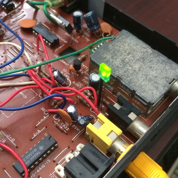
The main PCB is only single-sided, but for board interconnect Casio hand-soldered some wire all over the place. It’s really ugly (and gets in the way of probing pins) but this machine screams “built to a price.” NEC or Sony would have made this thing a double-sided board that costs six times as much…
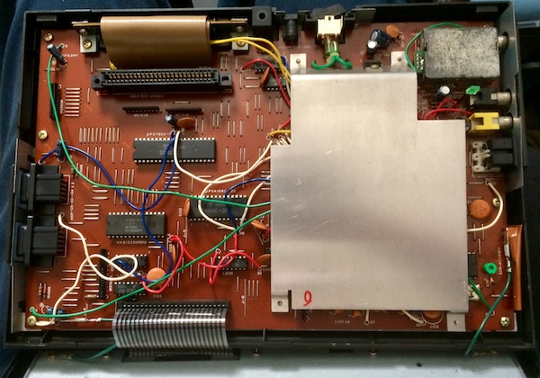
This giant heatsink is for cooling the 5V voltage regulator, as well as probably some kind of other purpose that I can’t see. It’s awfully big: I wonder if Casio stole this from some other product under development to save a few bucks. The screw that holds on the regulator is not the same as the ones that hold the heatsink to the board.
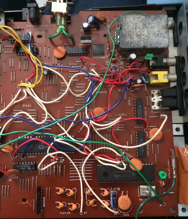
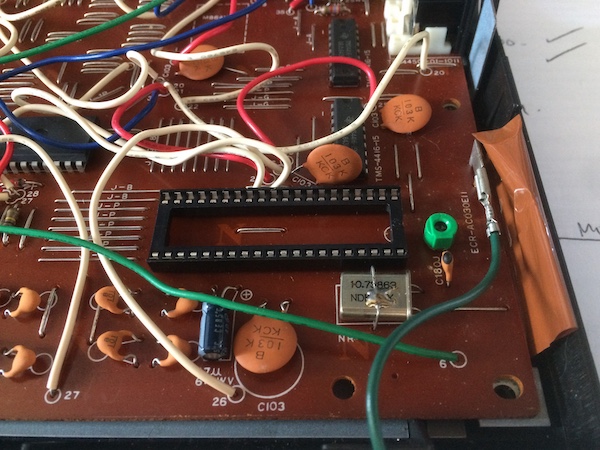
Under the heatsink is the AY-3-8910, some RAM, and the TMS9118NL (not 9918) graphics chip. I really like how the board calls out capacitor values right on it; it’s like working on a high-end stereo instead of a pedestrian piece of computer equipment. I’ve never opened up a Casio anything before, so it could be that they all do this.
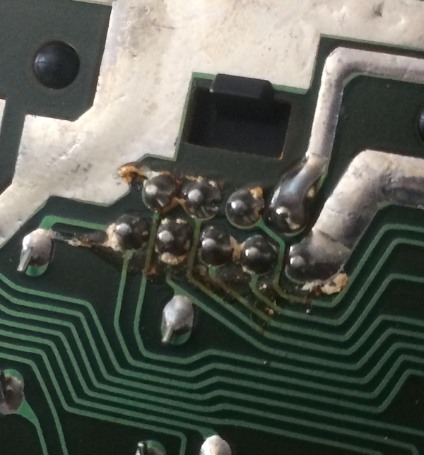
Some of the solder joints around the joystick ports are really gross. Maybe someone spilled something in here, long ago. It looks like the ‘joypad’ part of the keyboard is directly wired to Joystick #1 through the port pins. Now that’s pretty lazy clever.
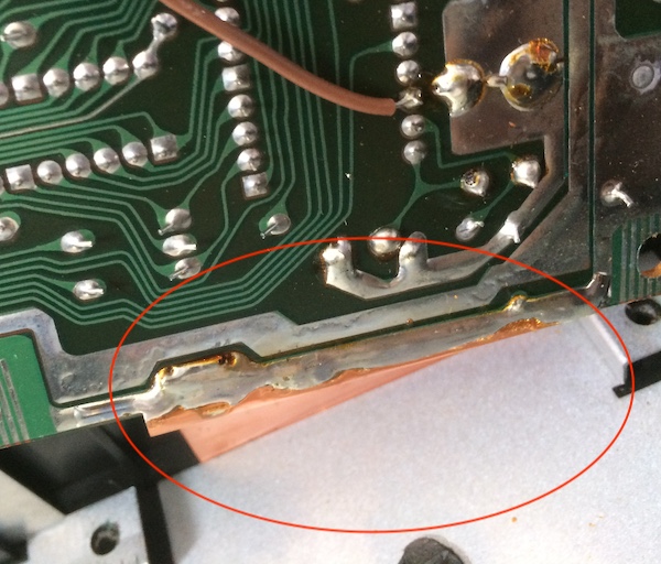
The motherboard is soldered to this awful copper tape for I assume RF compliance. This means it’s difficult to remove the board without desoldering it from the metal RF shield beneath. I tried to desolder it, but I decided I would rather not risk pumping that much heat into the board yet.
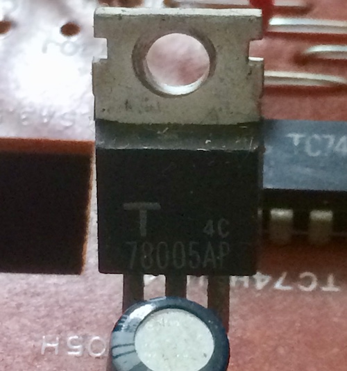
After a while of looking around inside the dismantled computer, I didn’t find anything that looked suspicious. That’s when I decided to put it back together and probe for voltages. I was seeing 0V on both the output and input sides of the 78005AP 5V regulator!
I accidentally bumped the machine while testing and the power LED jumped to life. Was it really just a bad solder joint on the power jack?
I rotated the barrel jack around a bit, and in one position the power LED would go on and stay on. The output side of the regulator was a solid 5.00-5.02V, and the input side is a naughty 12V, 2V higher than the 10V rating on the brick. That power brick - which is just a little bit older than me - is definitely starting to drift. It’s a good thing the regulator is such a little hero.
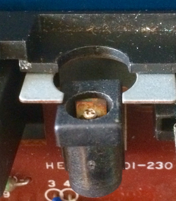
After looking at the power jack closely, I realized why I wasn’t getting good contact. The metal inside the jack that connects to the ‘barrel’ part of the plug is very oxidized. I’ll probably replace this jack later, possibly when I find a new, safer, power supply for the machine.
However, there was still no video; nothing seemed to be establishing sync. I’d get a little flash when switched on and then nothing… I wiggled the composite video jack, figuring it might also be loose, but no position seemed to make a difference.
I put the logic probe on the CPU, and it looked like the clock was good, reset was working properly, activity was happening on the address and data pins, and it was making memory requests. Sounds like the CPU is okay? It struck me as very weird that the /IORQ pin wasn’t lighting up - in order to read from or write to the video chip, the MSX has to hit I/O ports just like on the ColecoVision.
Unlike the ColecoVision, the PV-7 uses a TMS9118 VDP instead of a 9928. The RAM interface is different - that’s why it only needs two TMS4416 video RAM chips.
When inspecting the area around the TMS9118, I noticed that it has its own dedicated 10.73863MHz crystal. That’s not cost-effective, Casio. You should do some freaky analogue-domain stuff to generate a clock multiplier, like Coleco did. Maybe they should have anyway, because both legs of that 10.7MHz crystal (and correspondingly, the XTAL2 and XTAL1 pins of the TMS9118) were pulled low.
I first started with the video RAM. On the TMS4416 video RAM connected to the TMS9118 video chip, I only saw /RAS to be low and /CAS to be high. Boy, they should be cycling…
So we know that the TMS9118 video chip is just not doing its job inside this little MSX. I have never encountered a bad crystal before, and there’s nothing in between the crystal and the XTAL2/XTAL1 pins of the TMS9118. Maybe the video chip got fragged from ESD one day from having composite video plugged in on a shag carpet?
Flummoxed, I started searching around. One of the first places I found was this Japanese blog, where the intrepid repairperson had this to say:
The system did not start even if the power was turned on when this PV-7 was obtained, but it was restored after replacing the VDP.
That’s a bit of a coincidence. I was beginning to suspect a design flaw. I definitely didn’t have a replacement 9118 VDP on hand.
Putting the mega-hurts on the TMS
While I waited for a few TMS9118s to arrive from Aliexpress (at surprisingly high cost compared to the “normal” TMS9918), I decided to make use of a new toy - my el-cheapo frequency counter. Could it see a clock even if the logic probe could not?
The frequency counter came with two wire harnesses to solder up: one is for power (+, -) and the other is for frequency analysis (a little wave icon and a ground). When I first set it up, to try and figure out what voltage it likes (anything over 7.7V; 9V-12V is nominal), I put it on the bench supply. Once I put enough power into it and it leapt to life, I noticed that it was reporting 45MHz when not hooked up to a frequency source. Clearly, it is very sensitive to any noise in the power supply.
I wired it up to a 9V battery to try and eliminate that variable, and with the 9V battery it correctly reports 0MHz when not hooked up to anything. Always test your tools!
I also checked it against the Leako clocks when I was working on the earlier boards of that project, and it helped inform me that I had wired up the TMS clock completely wrong as a result. It’s a nice tool to have around, even if getting it set up was a little rustic. My Tektronix 2246 oscilloscope also has a frequency counter (since it’s pretty easy to implement once you’ve done everything else to build an oscilloscope) but dragging a bulky 80s scope out and setting it up is not always feasible or pleasant, so it’s nice to have a more portable alternative.
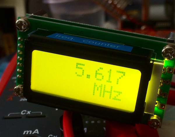
In any event, when I hooked the counter up to the MSX, the frequency counter reported 35MHz when hooked up to the crystal - whether or not the computer was on!
So, the answer to my question was “no” - the frequency counter isn’t magically better at seeing the presence of a clock than a logic probe.
It is, however, a very useful little tool. I’ve used it on the the ColecoVision clone already to debug that TMS VDP (see above - the clock there is definitely not 10.73863MHz.) More on that project soon!
Texan Masticator of Scanlines
Aliexpress came to the rescue with a collection of TMS9118s. I made multiple orders, because of the unpredictability of Coronavirus-era shipping. One order came first, with two TMS9118s jammed into regular old white staticky styrofoam in a manila ePacket envelope (come on!)
I flipped the board over. At first, I was going to remove the copper braid so I could more easily solder to the board, but there was enough room to work with. Also, my iron was struggling to transfer enough heat to reliably desolder and re-solder this grounding line, and I figured I was already taking enough risks.
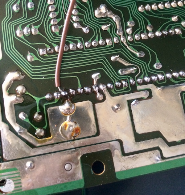
I retained this brown bodge wire. It’s a little hard for me to count pins when I’m flipping the board over all the time, but I think this is the CD6 pin. This runs to a weird pad on the other end of the board, which I think might be part of the expansion header.
The TMS9118 came right out with no problems - it practically fell off the board after I desoldered all of the pins. I wish every through-hole desoldering job was this clean!
I popped in a socket from my stock of them. The DIY-ColecoVision project has added a lot of TMS-related parts to my inventory, that’s for sure! This is just a regular cheapo single-wipe socket. The additional height didn’t interfere with the heat sink, and the additional width of the socket didn’t interfere with any of the bodge wires or caps in the area. It looks like it was meant to be here.
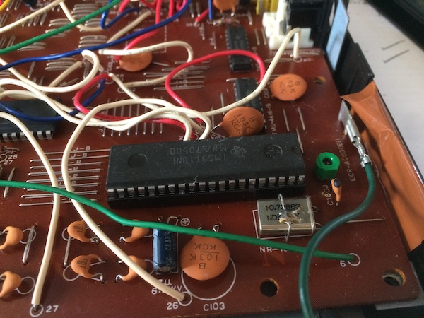
And then I put one of the Aliexpress VDPs in. The “new” chip came with the legs all splayed out, so I gently rolled it on my ESD mat until the legs would easily fit into the socket.
Fire one!
I put the motherboard back into the case and then wired it up to my composite capture rig. The computer sprang to life when the switch was hit and showed the MSX boot screen, and then MSX BASIC.
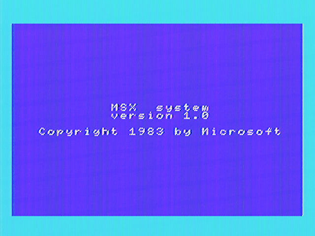
It’s alive again!
I wasn’t sure that the old TMS was actually bad. It’s definitely possible that the bodge wire was somehow damaged by being pierced by a pin (Jan Beta style), but I didn’t notice any perforations on the insulation when I was checking it out. Just to be safe, I wrapped the wire in Kapton tape before reinstalling the board to give it a bit more protection.
I swapped the TMS chips back just to be sure (after all, it is now socketed) and got the same behaviour as before. The experiment was conclusive: the TMS that came with the PV-7 was bad, and so it must be thrown into my bucket of bad parts until perhaps some future miracle occurs that revives it or I toss the contents in the trash.
Let’s get back to the new, good, VDP:
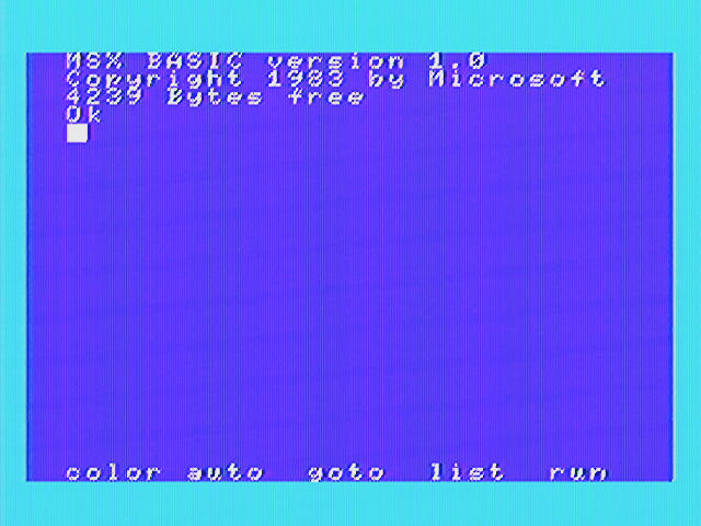
Boy, 4239 bytes is not a lot of free RAM! Whatever are we going to do about that?
Putting it back together
Putting this machine back together is kind of fiddly. You have to line up both the very long-legged power LED and the cartridge slot and then do up a bunch of plastic snaps. I got it eventually.
I noticed also that the peeling surface on the keyboard overlay was actually just removable cling-film on top of it. Peeling back the 37-year-old cling-film gently, I discovered the actual overlay was beautiful and shiny. Just look at this thing! I’m not sure if I should clearcoat this in order to protect it, since it’s surely a fingerprint magnet.
Unfortunately, when I fired up the MSX and tested with the keyboard, I found out none of the keys on the keyboard worked. It’s going to have to come apart again for a cleaning and potentially a trace repair. Kind of a bummer - I hope it’s just a cleaning like this other PV-7 user had to do. There’s not a lot of other repair info, possibly because nobody bothered to save an MSX with only 8kB when they were plentiful.
On the plus side, the PV-7 immediately fired up my cartridge copies of Door Door mkII and Adventure Island, which are the only two MSX games I own. A joystick plugged into port one worked great, and the machine seemed generally happy overall.
I’m pretty pleased I could save it, even though there’s more to do:
- Fix the keyboard;
- Replace the corroded power jack;
- Upgrade the RAM!
Repair Summary
| Fault | Remedy | Caveats |
|---|---|---|
| Black screen on power | Socket, replace TMS9118 VDP. | Hard to get this variant. |
| Keyboard does not work | Not remedied | Joystick works OK at least |