Ms. PC-9801 if you're NS/T
Tags: computer pc98 pc9801nst pc9801 nec repair batteries capacitors corrosion
I got ahold of a PC-98 laptop. Unfortunately, it has a lot of battery leakage and won’t power on. Come hang out and smell the vinegar with me for a little while.
For the last few months, I’ve been trying to get a working PC-9801N laptop. I have had little luck, as basically the same parts are damaged beyond repair from battery leakage on every machine. With some more effort, I think I will one day be able to save one.
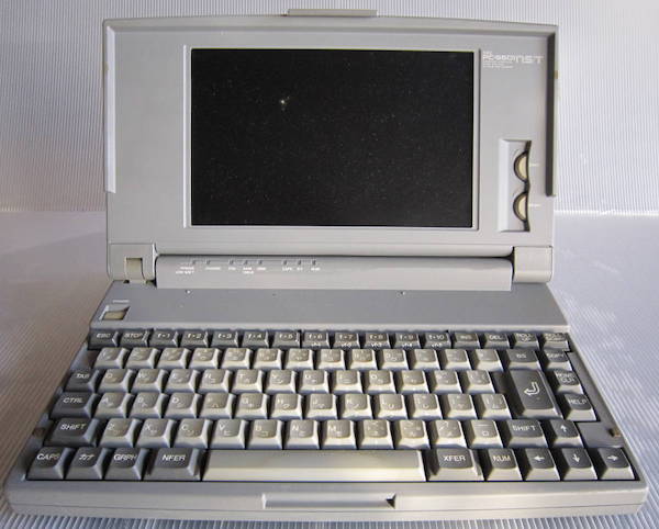
While I was looking for more 9801N parts machines (they’re very cheap - because they’re all scrap), this NS/T showed up. I figured it would be an easier project than the 9801N, and possibly use some of the same parts, so I grabbed it. The NS/T is a much more powerful machine - it’s 386-based instead of an 8086-equivalent NEC V30.
It has a 2-bit (4 colour) monochrome LCD screen, a floppy drive, and a unique “RAM drive” that lets you pretend to have a second floppy drive by imaging a floppy into RAM. This RAM drive, of course, requires a large rechargeable battery to sustain it…
Looking Deeper
NEC did not really learn from their mistakes regarding battery leakage in the original 98Note - if anything they added more batteries. There’s a big “regular” battery, a big standby battery presumably for when you are swapping the regular one (new!), a big NiCad battery pack like that in the 9801N to sustain the RAM-backed second virtual floppy drive - which has leaked, and a lithium coin cell battery on the motherboard. That’s absurd, NEC. You should be ashamed of yourselves.
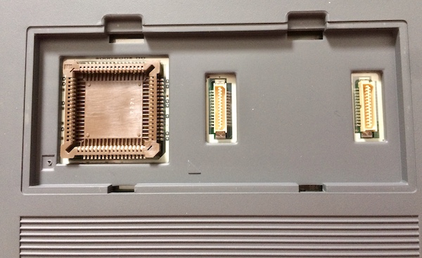
Not wanting to stop there, there are two ways to add extra RAM to the machine - a 9801N-compatible RAM module that plugs into the bottom but offers slower speeds, and a door on the underside that accepts a new-style, lightning-fast RAM board as well as a floating-point co-processor. Neither are loaded in this machine.
One weird thing is that the lid says “SX/T,” while the display bezel and model sticker on the bottom both say 9801NS/T. As far as I can tell, this is normal for this machine. I guess they were really excited about having a 386SX?
![]()
![]()
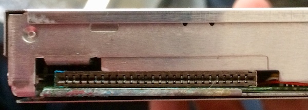
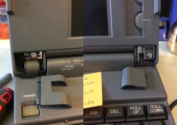
There’s a bay around the side that I think is for installing a hard drive. I don’t have a hard drive; the bay is just empty and doesn’t even include the screws. The connector is some weird-looking parallelogram from Hirose, so I think it must be another proprietary PC-98 hard drive sled like on the PC-9821Ap2.
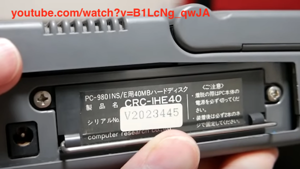
Here is a picture from a helpful Japanese YouTube video series about another battery-damaged 9801NS showing an installed hard drive caddy. It has a similar pull-handle to the sled in the Ap2.
To open the laptop itself, you have to pop off the plastic hard drive cover around the DC jack (it slides back,) unscrew all the screws you can see, pop out both ‘top’ batteries, and work your way around the front of the top case carefully popping clips with your thumbs until the display top case comes loose at the front. One interesting side note is that the keyboard seems to be identical to the one in the 9801N. This is good since the NS has a gross keyboard, and as I’ve already stated, I have lots of 9801N parts machines.
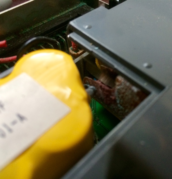
Then you can remove the special little door, which reveals a battery hiding under a battery. I can’t figure out a way to get this out without taking the whole top of the machine off, but the door also seemed to get in the way when I was removing the top case so it’s worth removing. This leaky backup battery is almost certainly where our problems have begun…
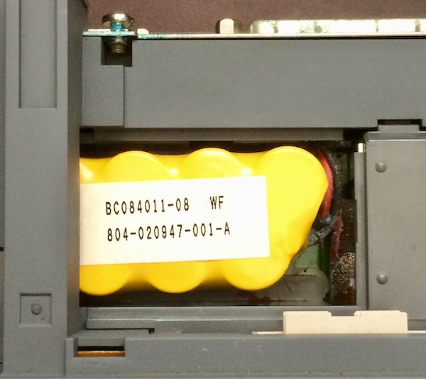
I cannot find any information on this battery, but there exists a Yahoo! Answers thread where a Japanese owner is convinced it is keeping his machine from starting. There’s no positive resolution to the thread, but I’m not so sure that we actually need this RAM backup battery to be present in order to start the machine. I suspect a failure somewhere else is to blame for the no-start condition.
With the top off, there’s this big plastic chunk that provides support for the case and also holds onto the clock battery, all of the battery charging circuitry, a speaker, and the 3.5” floppy drive.
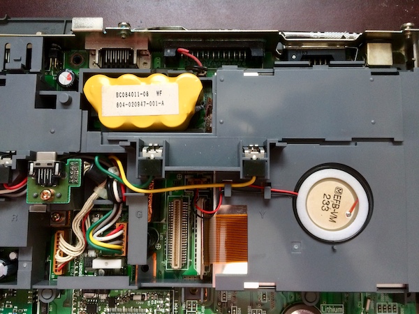
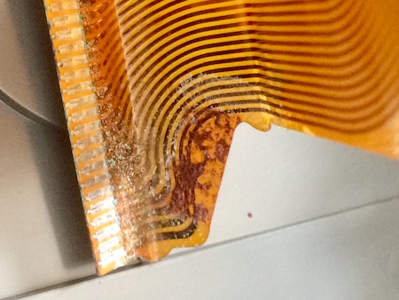
The plastic has shielded most of the battery acid from spraying all over the motherboard, which is nice. Unfortunately, it sprayed on the FD1139C floppy drive and its FFC ribbon cable instead…
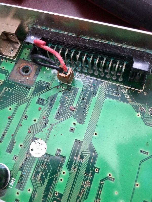
Rather than fight with the battery harness, I just snipped it off. And by ‘snipped’ I mean I touched it and it turned to ash. This was a non-cable. It sure left a lot of gunk behind, though, including inside the RS-232 port:
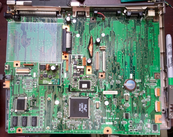
Now I can see the top of the motherboard. It’s really pretty! I would appreciate NEC’s weird grid system (see the south border) more if I had a service manual to go off of. You’d be able to find components in a hurry!
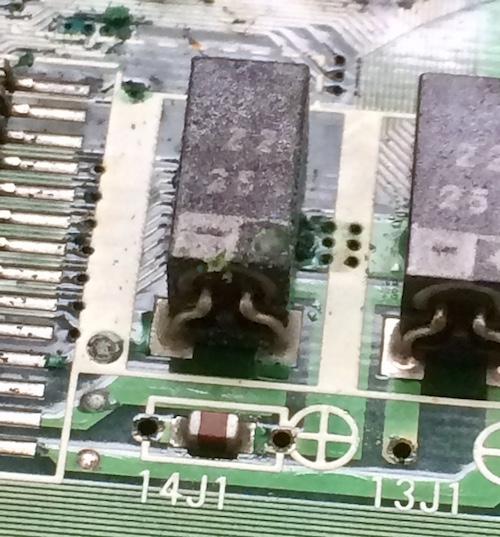
I’ve found in my research that the usual 9801N afflictions (bad power board caps, backlight failure, screen hinge breaking) also affect these, so I took an extra special look at the Murata analogue board to the side of the power board in the middle of the motherboard. It has these weird giant surface-mount ceramic caps, which look like they got very toasty at some point:
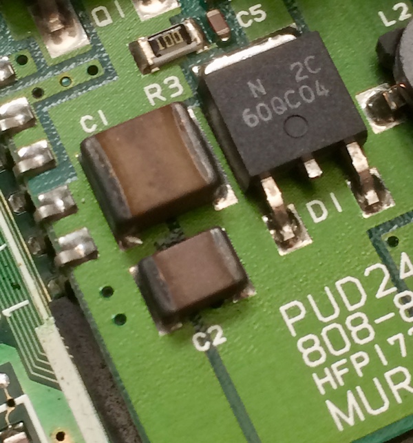
After tapping them with a little bit of isopropyl alcohol, the q-tip came back bright green (battery goo!) and the capacitors looked fine. I guess that’s what you get when you mix those two gross colours together.
Once I flipped the board over, I got a pretty good look at the huge custom NEC ICs. Lucky for me, their legs and packages looked clean.
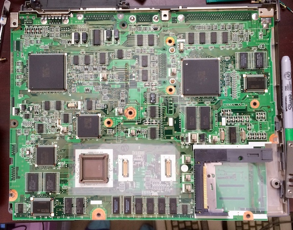
Unfortunately, there were also more electrolytic capacitors, and they’re not the good kind. There was also a lot of corrosion blooming out of vias as well as stuck onto traces, which means that there’s at least one broken trace in here somewhere.
Apparently the “engineering name” for this style of capacitor package is “chip electrolytic,” but I have mostly seen them previously in Sega’s Game Gears. What’s important is that I know they are prone to leaking like crazy, and one of them has sucked up a good lungful of battery acid to boot. These caps are probably bad, although they are unlikely to be the primary culprit of a no-start condition.
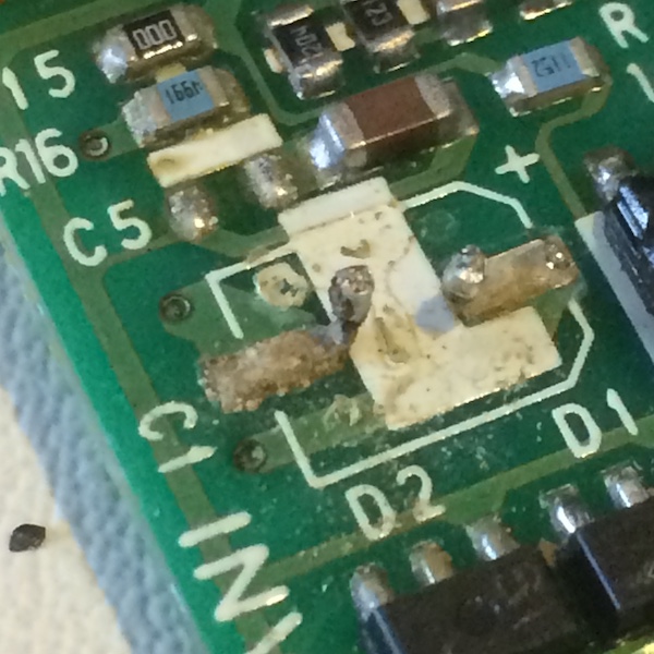
There’s one 10µF surface-mount can cap (C2) on the power board, too, and it definitely has been leaking:
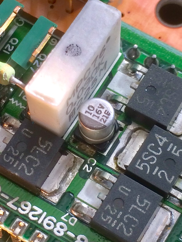
Probably all of those huge diode packs were also putting out enough heat to cook that little cap. It looks like the pads are even damaged enough that the legs are no longer making contact, which could mean the no-start condition is just a mere open circuit. Lucky for me, I have a bunch on hand from recapping the Mac LC, and so I decided I’d just throw one at it to see if it would help.
It was a little tricky to get in with all the other components in the area, so I ended up making a bit of a solder glob on one end, but it worked.
While I was in there, I also noticed that the 270µF through-hole electrolytic cap on the Murata board appeared to be a little domed. I desoldered the sub-board and removed the cap and found that it had basically puked all of its guts out:
Yuck! It cleaned right up with some alcohol, but it’s always nice to see an indicator like this that you’re on the right track.
I had those on hand as well (thanks, previous 9801N recap attempts!) so I slammed them in. The new caps have a superior vent design, and are also (in the case of the 330µF and 220µF caps) a lot smaller than the originals.
Ohayo World
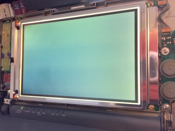
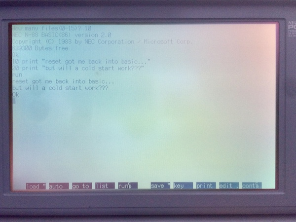
After loosely installing the display, I plugged the machine in and fired it up. It immediately sprung to life, quickly emitting some Japanese warning that I couldn’t read in time and then dropping into N88-BASIC, just like my Ap2 liked to.
The keyboard seems to be fully functional, although cramped and awkward to type on. It felt like I was always typing one key to the right. The floppy light was on solid, owing to the complete lack of a floppy drive.
This screen was impossible to photograph! I have read that the backlight driver board often has bad capacitors, but I had some backlight. It seemed like the contrast was pretty dim and the screen is very reflective, so I would just end up taking blown-out pictures of my phone instead of the screen.
Without thinking, I shut the machine off after only a few minutes to see if it would power on again. Then I turned it back on. Now, all I got was the power LED and the backlight. Nothing seemed to work. After a few more power cycles and jiggles, I no longer got the backlight, either. It seemed that one of the components I didn’t replace just gave up the ghost after being introduced to its first new current after a few decades.
The important thing is: now I knew it could work.
Full Partial Recap
If at least one cap was bad enough to be domed, probably all of its friends and relatives are not in great shape either. Also, I may have imagined it, but I smelled a distinct fishy odour the first time the machine failed.
Right next to the power board, I spotted 12F1, one of the 220µF capacitors, that had also domed. I don’t know if I missed it before and it had always been that way, or if I just put a little bit too much strain on it during the test run, but it was time to replace it.
I tested again after replacing just the 220µF and 330µF through-hole caps on the motherboard: no dice. Diagnosis is hard; let’s stuff caps.
My luck on having replacements on hand ran out here, and I had to place an order.
Here’s a cap list of the motherboard:
| Position | Capacitance | Voltage | Notes |
|---|---|---|---|
| C7 | 270µF | 16V | Murata board |
| C11 | 27µF | 25V | Murata board |
| C2 | 10µF | 16V | Power board; SMD button cap |
| 13H1 | 330µF | 16V | Mainboard; through-hole |
| 12F1 | 220µF | 25V | Mainboard; through-hole |
| 8J3 | 220µF | 25V | Mainboard; through-hole |
| 15J2 | 22µF | 25V | Backside; rectangle SMD |
| 15J1 | 22µF | 25V | Backside; rectangle SMD |
| 14J1 | 22µF | 25V | Backside; rectangle SMD |
| 13J1 | 22µF | 25V | Backside; rectangle SMD |
| 14G1 | 22µF | 6.3V | Backside; rectangle SMD |
| 8G1 | 22µF | 6.3V | Backside; rectangle SMD |
| 20E5 | 1.5µF | 50V | Backside; rectangle SMD |
| 20E4 | 1µF | 50V | Backside; rectangle SMD |
| 13E1 | 22µF | 6.3V | Backside; rectangle SMD |
| 16D1 | 22µF | 6.3V | Backside; rectangle SMD |
| 11D3 | 22µF | 6.3V | Backside; rectangle SMD |
| 6D1 | 22µF | 10V | Backside; rectangle SMD |
| 5D1 | 6.8µF | 35V | Backside; rectangle SMD |
| 4D1 | 22µF | 6.3V | Backside; rectangle SMD |
| 7C2 | 22µF | 6.3V | Backside; rectangle SMD |
| 7B3 | 22µF | 6.3V | Backside; rectangle SMD |
| 7B2 | 22µF | 6.3V | Backside; rectangle SMD |
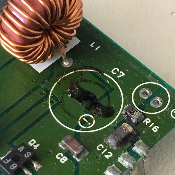
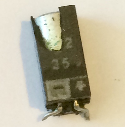
14J2 was a particularly pukey cap. Battery acid had gotten trapped under it where it was glued to the PCB, and filled up all of the vias underneath as well as crept into the cap.

The plastic body of the cap broke as soon as I touched it with my finger to wiggle the glue loose:
An ugly mess to be sure! It also stunk of fish and took a million years to clean up the pad. This one had puked for sure, even though a lot of its 22µF neighbours did not.
I found a post where a similar problem had happened under the 15J1 capacitor, which severed a trace needed for the hard drive controller.
I mounted some cylindrical 22µF electrolytic capacitors in the same way, with the leads bent in a sort of “kneeling” position. I had ordered some surface-mount ceramics with the plan to ‘bridge’ these pads as they were just close enough to reach, but I had heard the capacitance drops very quickly as they approach their voltage limit, so I ended up just using the el-cheapo can caps in an awkward fitment.
The 3-pin surface-mount component in 12D1 had drank quite a bit of acid and its joints were badly corroded as well, with some crusted-up battery electrolyte trapped underneath it. I used a magnifying visor to read “S33” off of the top, but all I could find for that tag were 5-pin linear voltage regulators. That’s a shame, since I would have preferred to replace that part with a fresh one. I cleaned and reflowed the joints just to be sure.
I also went and reflowed the surface-mount cap on the power board, because my initial joint was really sloppy. With an appropriate amount of flux, it flowed like quicksilver.
Firing it up again after only replacing the 22µF caps, I noticed no real difference in behaviour. This is probably to be expected, as I hadn’t replaced all the caps yet and also it was unlikely to ‘just’ be caps if the problem got worse on successive power cycles.
I hooked up the speaker to see if there might be a boot sound (“pipo,”) but I didn’t observe one on cold boot.
After unplugging the speaker and trying to boot again, I noticed - purely by accident - that the contrast and brightness wheels still worked. More importantly, I found out that the reset button works. Pushing the reset button would make the Caps, Kana, and Num lights faintly flicker three times in quick succession.
I discovered that doing this reset must take the machine past something that was hanging on it - because now the caps lock, kana, and num lock keys toggled the lights. I also saw, just for a brief millisecond, some very-hard-to-read Japanese message similar to the original boot message appear: matte black pixels on a gloss black screen.
After poking around for more damage, I noticed a nick in the insulation of one of the screen wires. I didn’t think it was important - and it didn’t seem to be down to the copper inside the wire. I wrapped it in Kapton tape just to be on the safe side.
So I knew the following things about the machine:
- The ‘computer part’ works when it has good clean power;
- The backlight can come on, but it’s dim;
- The display is still working;
- Hitting “Reset” gets me somewhere different than just starting up the computer cold, somewhere where the caps lock key works
I had some theories:
- Maybe the clock battery has sort of “half-kept” the BIOS settings after the only successful cold boot, and that corrupted setting means that the computer is getting into some impossible state where it cannot continue;
- One of the caps I didn’t replace (i.e. every non-22µF one) was bad and needed replacement;
- Something in the display is drawing too much power and keeping the computer from coming up all the way;
- Something in the computer won’t come out of reset from a cold start, even if you on-off cycle it;
- One of the vias under 14J2 has failed and its trace is somehow important for the proper function of this machine;
- A witch has cursed me.
I desoldered the last remaining battery, the lithium VL-2320 clock battery (measured voltage: 2.08V/3.0V; there’s no way it was keeping anything), and tried to start it up again. No difference, and with enough on/off attempts, even the Reset trick no longer seemed to work. At least the load of recharging this battery was now lifted from the power circuitry.
A Brighter Future Awaits
I also wanted to open up the display and finally get at the caps here. Luckily, a Japanese enthusiast had posted a video with a full re-cap of the 9801NS/T that includes this sequence of opening the display panels. Steeling my nerves, I worked to free the ancient plastic from itself.
You start by removing these two little doors on the hinges and then you can pop the retaining screws loose and work around the perimeter. The clips on the bottom are tricky, so don’t leave them until the end like I did.
Notice the huge gouge in the plastic on the left side. Be very careful not to slip when you are, say, using a flathead screwdriver to pop the clip. Not that I would ever do that. Must have been some guy in Japan.
Make sure not to lose the little tension clip on the left side. I think it’s for making contact with the switch that turns off the backlight. It’s a little hard to align back onto the plastic pegs if it does fall off, but you can do it if you slip the metal in at the top first and work your way down instead of the other way around.
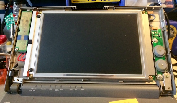
At last, the screen is exposed. I’ve never dismantled a laptop LCD before. It feels kind of perverse, like I was not meant to see it naked.
This was a surprising amount of work. There are lots of clips around the perimeter and I scratched up the plastic very badly. At last it was loosened.
I pulled the contrast/brightness dial board first, but it doesn’t have anything of interest. Then I pulled the backlight control board - made by our friends at Toshiba.
This one has a very loose connector, which initially I thought was caused by these corroded solder joints:
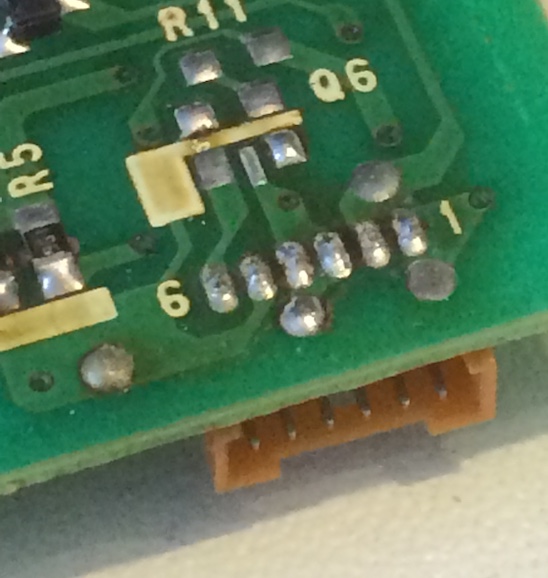
But cleaning the joints and re-soldering them didn’t do anything to fix the looseness. Just be really careful when removing the top harness. There was also a surface-mount resistor that had drank a little too much cap juice. I cleaned up that pad and resoldered the resistor.
The 47µF electrolytic cap on the topside of the backlight board is shot:
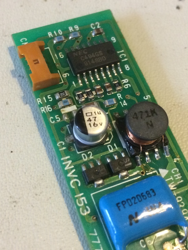
The legs are attached to disgusting-looking pads, but it did clean up. After cleaning up the joint and the rest of the board, I slammed a new cap in from my “classic Mac caps” pile.
I couldn’t wait to reassemble everything; let’s fire this puppy up.
Holy shit, that’s bright. But still nothing is happening. Let’s try hitting RESET and see what it was doing when the caps lock, num lock, and kana lock keys were working.
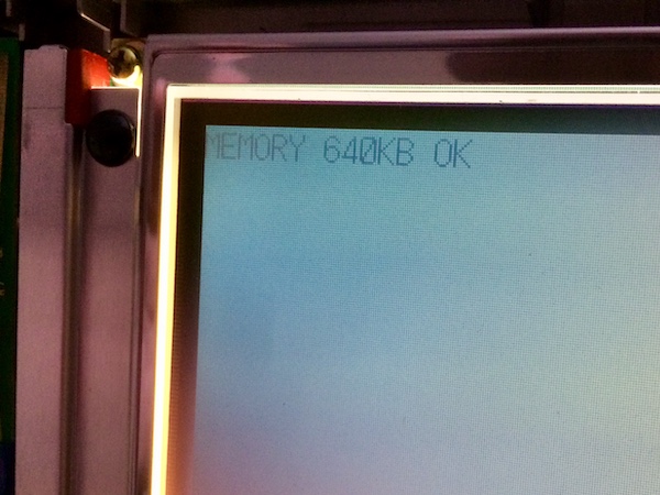
At least the memory is OK. Sometimes it freezes on this screen, but other times it advances to a blank screen instead of N88-BASIC like I expected.

I caught a glimpse of that Japanese message that comes up at startup. It says something like “initial settings restored, perform setup” which is not surprising because I just desoldered the BIOS battery.
I can’t believe how nice this display is now. Now I’m going to be questioning every LCD in my house about whether they also need a visit from Dr. Goodcaps.
After carefully re-assembling everything and swearing at the “screen open” latch a few times (the long part of the spring goes at the back, resting on the two little nubs on the front half of the screen), I put the machine back into its corner because another project came up.
This ‘98 has a beautiful white display - it might even be nicer than the period PowerBooks. This machine must have cost an absolute fortune when it was new.
Now all I need is a booting computer to go with it.
Finish the Job
After thinking about the problem for a little while, I decided I would replace the rest of the motherboard caps. After all, I bought them to use them. A little cap shotgunning can’t hurt, right?
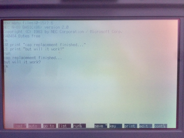
I replaced the 22µF/6.3V caps first (with 22µF/25V ceramic caps - 14G1 was especially leaky) and gave the machine another test run. To my delight, it booted right into N88-BASIC after giving me the MEMORY OK and default settings warnings.

I wrote a quick BASIC program to test that it worked, and it did.

However, just like before, when I turned the computer off and back on again, I couldn’t get it to work. Still though, this was progress - of a sort.
A Recap in Four BASICs
Now I replaced all the rest of the caps (1µF, 1.5µF, 6.8µF and the oddball 22µF/10V) and fired it up.
It sprung to life, as it has many times before. But was it getting ready to betray me?
It still worked after pushing Reset, which was a good sign… but does it work from a cold boot?
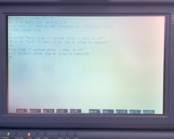
It worked if I shut the power off and back on again. Would it work if I pulled the plug entirely?
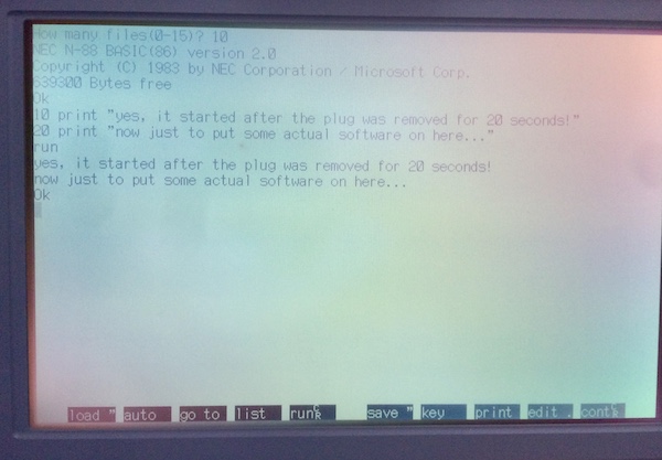
Wow! It might be fixed.
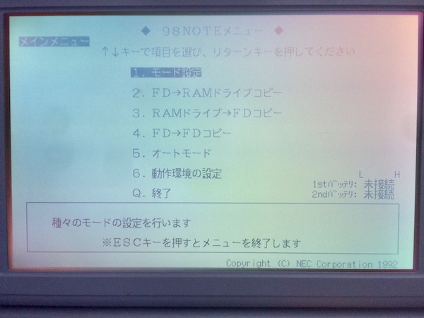
I decided to take the opportunity to check what the soft-DIPs had to say. By holding HELP down at startup, like on my desktop PC-98, it will drop into this PC BIOS-like screen where you can configure various properties. I can understand none of this, except for the last option, which is “end” or “quit.”
Based on the “FD -> RAM” and “FD -> FD” options, I’m assuming this is where you would copy floppies into the long-term memory or duplicate floppies.
So What Was The Problem, Smart Guy?
I don’t have much of a diagnosis for what actually went wrong, but my guess is that one of the faulty capacitors was able to hold the machine (or some component of it) in reset for a very long time, possibly from being internally shorted. Removing the capacitors for previous re-cap attempts must have drained that cap long enough that it would no longer hold the machine in that bad state. However, I have no evidence of this being the case.
Now What?
The PC-9801NS/T is alive again, and that’s a good enough place to stop for the time being.
For the next steps, I want to get the floppy drive working - or a floppy drive, at least - and then try out some PC-98 software on this beautiful paper-white monochrome display. The corrosion on the serial port is very concerning, but I haven’t had any luck finding a direct replacement for it, nor have I buzzed out the potentially damaged traces to see if they need to be bypassed.
In the distant future, I think it would be nice to hunt down a hard drive upgrade. Curse NEC and their proprietary drive sleds!
Repair Summary
| Fault | Remedy | Caveats |
|---|---|---|
| Battery leakage corrosion | Remove batteries, clean leakage | More may lurk unseen, or have damaged traces for functionality that was not tested. |
| Does not boot | Replace some caps | Don’t know what actually made a difference. |