LJN Video Art Appreciation 101
Tags: console ljn-video-art reversing dumping homemade-hardware
In order to understand someone, it helps to learn how they think. To understand an obscure 1980s video game console, it helps to learn how it thinks. And how does it think? With cartridges. We’re gonna buy a cartridge for the LJN Video Art system, and build a dumper for it.
In my Discord server, a chatter named shellylynnx brought up the existence of the LJN Video Art and her enthusiasm for said machine. I had never heard of it before. Apparently, I was one of the few who hadn’t seen it getting excoriated in the seemingly endless YouTube Reacts To… hatewatching fad that spanned the far-off year of 2004 all the way to the present. Toymaker LJN, infamous for publishing poor-quality licensed games on the NES, had decided to make their own console.
As you might expect from the name, the Video Art system let kids (and probably some adults) paint pictures on the television set. The art looked chunky and pixellated, with a limited palette. That made me wonder if it was a Texas Instruments TMS9918A-based system, which would appeal to the part of me that likes cloning those consoles and computers.
After some more research, I discovered (and added to the Wikipedia page) that the system was actually based around a Thomson EF6805R2P microcontroller, along with their 16-colour EF9367 VDP. Some board scans of the Video Art console revealed that it has an onboard ROM containing a simple drawing program, as well as what I assume to be a common library of BIOS routines to ease development. The overall system has a surprisingly small number of parts in it.
I couldn’t find an affordable system for sale – it seems like Canadian distribution was minimal to non-existent – so I decided to do the next best thing. Even if I couldn’t get ahold of a real system for myself, I was still in a good position to acquire cartridges and dump them, so that emulators could be developed and the software preserved.
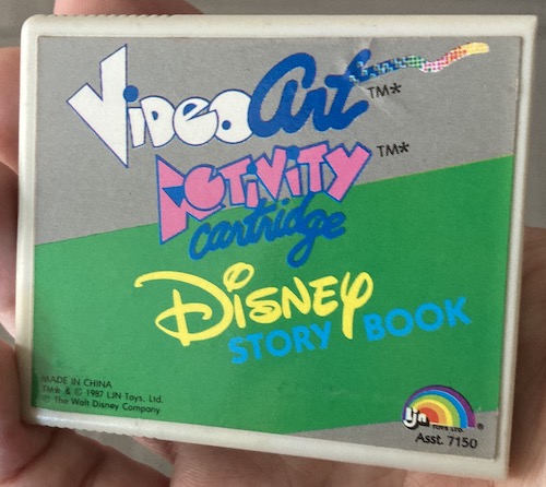
eBay provided a cartridge for $4 (plus a lot more for shipping) from eBay. It’s LJN Video Art Activity Cartridge: Disney Story Book.
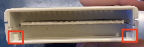
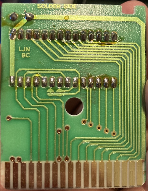
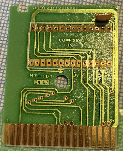
The underside reveals a 36-pin gold-plated edge connector (beveled, of course) with these polarizing tabs to keep you from inserting the cartridge upside down in the system. They are mounted on the solder side of the cartridge.
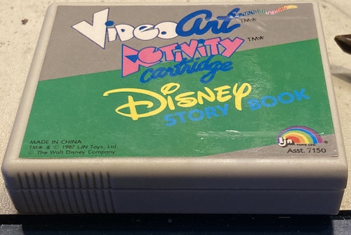
Look at how innocent it looks, landing on my workbench. It has no idea what’s about to happen to it.
Once the single screw is removed, two clips on either side of the cartridge must be pushed in to open the clamshell. With the right light, you can just barely see them through the gap.
The PCB has a notch in it to make it polarized, so that the solder side faces towards the label side of the cartridge. The cartridge pinout is numbered odd/even, with odd pins 1 to 35 on the backside, and even pins 2 to 36 on the label side of the cartridge.
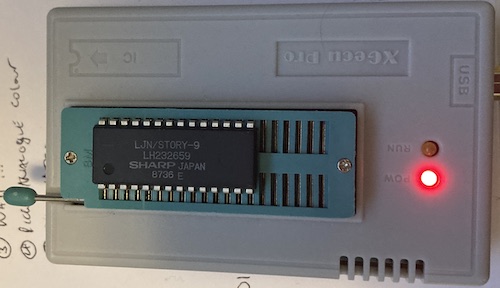
The ROM is found!
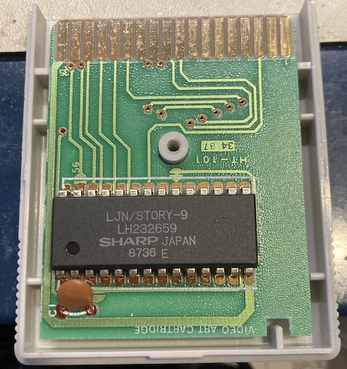
I didn’t have luck initially hunting down the Sharp LH232659 part number, and assumed that it was simply Sharp’s internal number for the specific mask that the customer had ordered. I was right, but I didn’t figure this out for a few more hours.
Eventually, looking in the Bitsavers.org copy of the 1991 Sharp Memory Data Book catalogue, I found this interesting chunk of the document. It would appear the true part number was LH23126, and is a 16-kilobyte mask ROM, roughly equivalent to a 27c128.
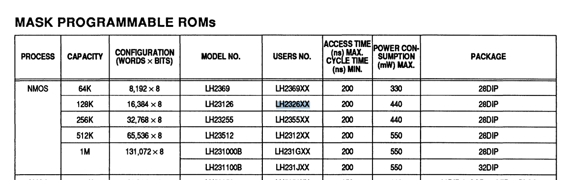
And sure enough, here it is later in the book:
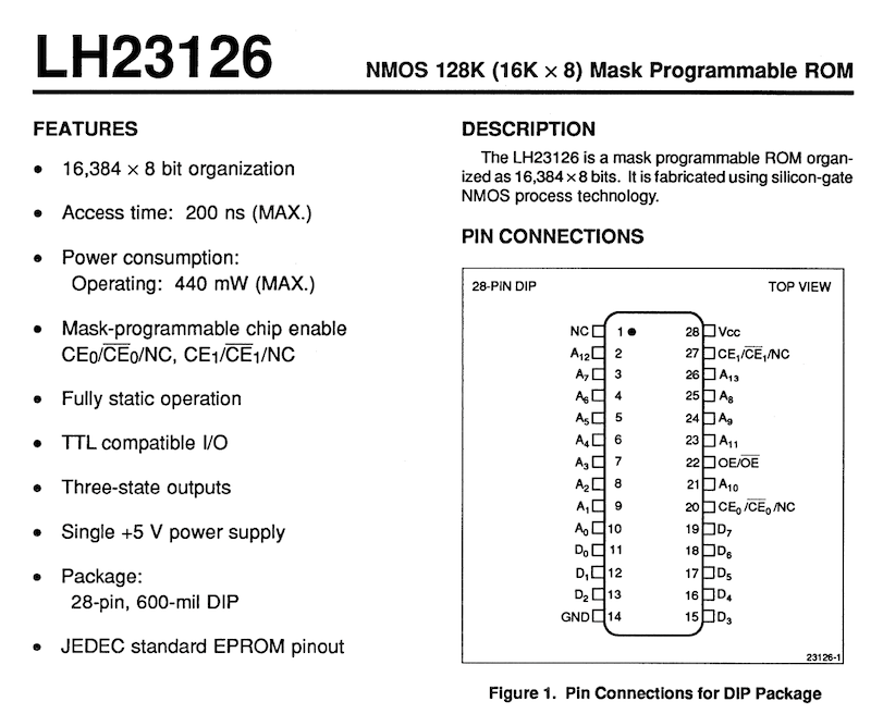
This mask ROM has two configurable chip enables, which is potentially extremely annoying – shades of the mini5SX all over again. But at least we have a pretty good idea now of what the pinout will look like – it’s JEDEC standard, thankfully.
Other Video Art cartridges seem to use a mask ROM sourced by General Instrument, with what appears to be the same “HT-101” circuit board, so their pinout is likely identical.
Tracin’
I started buzzing out the ROM to figure out which pins on the edge it connected to. This didn’t take so long, as the pinout is pretty reasonable. I found out that the pin on the ROM is shorted to GND, and the CE1 pin on the ROM is shorted to +5V.
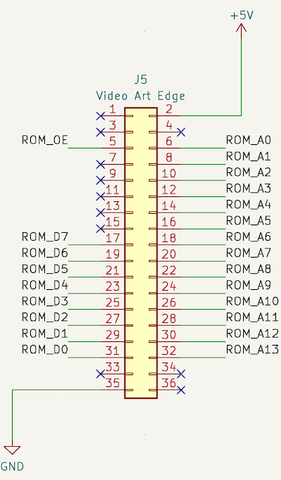
There are still a few mystery pins on the Video Art, as 11 out of the 36 pins were unused on this cartridge, which seems like a lot. I suspect that pins 1 and 3 likely do some kind of additional decoding, so that the cartridge can hold more than one ROM chip without needing to also add logic. That is a pretty common design of the period, also seen in systems like the ColecoVision.
Dumper construction
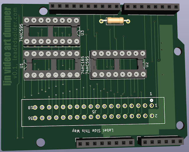
Since this was sort of a lark of a project, I decided that I would like to make this as easy on me as possible, so I went about putting the dumper into an Arduino Uno shield. This way, I didn’t have to think about USB-serial communication, or building a working microcontroller board. I would only need to buy some incredibly expensive male stacking headers, and some way to turn the Uno’s pitifully low 14 GPIOs into 14 address pins, eight data pins, and a chip select.
The answer to the second problem, as it is to most problems in life, is shift registers. With a couple inexpensive serial-to-parallel 74HCT595s, I can turn one serial data pin, one clock pin, and one latch pin into eight data pins. If I used two of them, I could easily control the 14-pin address bus from just three pins (one ‘595 can shift into another that’s daisy-chained on its output pin.)
On the data side of things, I could use a parallel-to-serial 74HCT165 shift register to compact the ROM’s 8-pin data bus into a single data pin (plus clock and shift-out pins.)
I had a lot of both ‘595s and ‘165s on hand from previous adventures, which made this solution all the sweeter.
In total, I’d end up only using:
| Signal type | Shift registers used | Total GPIOs |
|---|---|---|
| Address (14-bit) | 2 | 3 |
| Data (8-bit) | 1 | 3 |
| Output Enable (1-bit) | 0 | 1 |
| Total | 3 | 7 |
Plenty of pins to spare. Even so, I have only reverse-engineered Disney Story Book, and it’s possible that there are other cartridges out there that would use some of these unused pins, or have additional address pins or bank switching to support a larger ROM. I can’t guarantee that this dumper will work for every single one of the ten known Video Art carts, or the unknowable infinity of unreleased titles that may or may not exist somewhere out there.
There are probably other ways I could shave this particular pin count as well: I’m just counting up the address bus sequentially, after all, or I could use some kind of latch to control the address pins.
As for the connector itself, I found a 36-pin TE AMP female edge connector, 5530843-3. I asked for a free sample, and they went ahead and sent me one the very next day. I guess that makes TE Connectivity an unwitting (but consensual) sponsor of this project. They must be so proud.
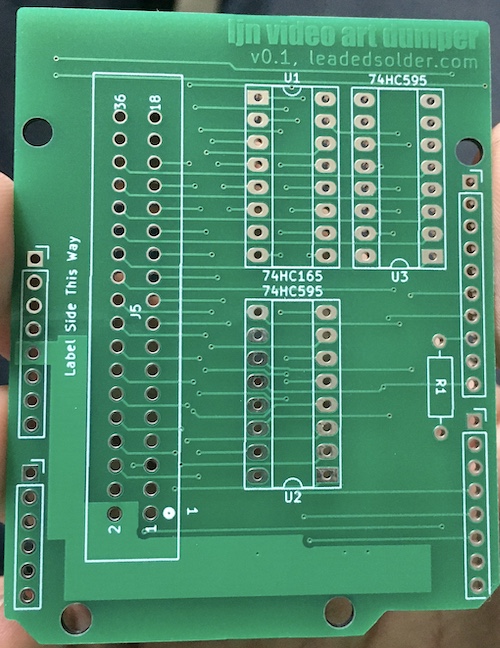
I don’t know if I will ever get tired of the feeling of opening a package containing a version-one PCB that I designed. It’s very satisfying to hold something in your hand that didn’t exist just a few weeks ago.
Unfortunately, the other thing I have gotten used to is that feeling of disappointment that something doesn’t fit or work properly. When the PCB arrived, I found out that the TE edge connector did not match the KiCad footprint that they themselves provided. I should’ve printed it out and test-fit it before ordering, but I was in a hurry.
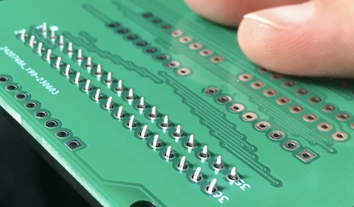
To fix the problem, I used some pliers and swearing to bend the edge connector’s pins closer, so that they would slot into the PCB. This is not exactly a reliable long-term connection, but to dump just one or two cartridges (there were only ever nine released!) it should do the trick.
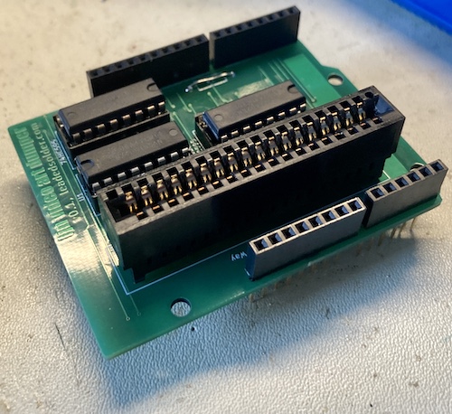
Connecting it to an Arduino Uno needed a stacking header, since a normal 0.1” pin header (of which I had tons) was not long enough to let the shield clear the USB port on the Uno. So I had to pay a crazy amount to get those from Amazon.
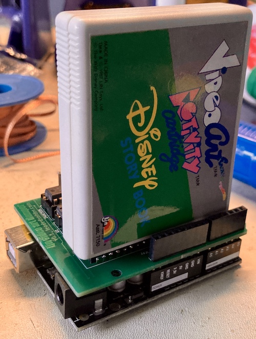
Even after I got the thing assembled, I noticed that I had inadvertently put the pins of one of the 74HC595s way too close to the USB port. If things wiggled, they would short out on the housing. Some kapton tape (barely visible in the above picture) fixed that problem, but I’m a little embarrassed nonetheless.
Firmware
Lots of bugs here, as you would expect.
On my first run of the dumper, I got nothing back but $FF . It turns out this was because I accidentally set it to active high output enable. Now I got nothing back but $00 . Removing the cartridge from the dumper and re-running the dump process generated nothing but $FF again, which convinced me that the output enable was indeed working.
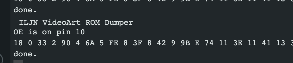
After a little fiddling with the order of enables and writes and making sure I got my latch and clock pins right, I ended up getting nothing but $18 . Ah, progress.
Dumper debugging
I put the address pins on the scope and was surprised to find out nothing was happening on either of the output pins on the address-generating 595s. They were getting data in on their serial inputs, and the clock and latch pins seemed to be oscillating, their output enables were shorted to ground, but nothing was getting latched in.
After hours of confused head-scratching, I eventually figured out that I had marked the active-low “reset” pin of the 595s as not-connected. At the very least, for reliability reasons, they should be pulled high if I’m not intending them to be constantly resetting.
Tying up this “reset” pin to +5V on both 595s made something plausible (and consistent) come out of the dumper, at long last:
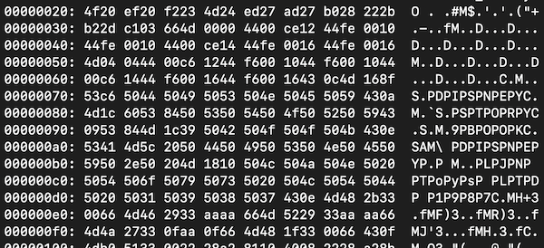
I shoved it through Python to convert it into a binary file, then opened it in a hex editor. My hope was to see a human-readable string or two that would help me figure out if I had a good dump, but no such luck. The file followed the general pattern of a ROM in terms of addresses, with nothing but a big chunk of $FF after $2dc2, but nothing jumped out at me as obviously textual data.
If I made a mistake on addresses, I might have made a mistake on data, too. I was not convinced that my ‘165 technique to read back the data bus of the cartridge was actually working yet, so I decided to poke a little further. Ghidra’s 6805 disassembler was having a lot of trouble with it, possibly because I hadn’t set up my memory map properly. For kicks, I decided to flip the data bus readout process to least-significant-bit-first, but this didn’t produce anything that made more sense. Throwing the ROM into my tile extractor script didn’t generate any legible tiles, either. I at least expected to see a letter, or part of Mickey’s head, but maybe the text tiles are stored in the console’s ROM.
Someone smart would have desoldered the ROM from the cartridge board and dumped it using a TL866 by now, to provide a useful reference. After a little bit of grumbling and looking at histograms of the dumped cartridge, that’s what I decided to do.
Desoldering the ROM from the board was pretty easy, and I got ready to shove it into the TL866. Here, I hit another obstacle. As we learned with the 23c4001 in the mini5SX, mask ROMs usually don’t behave in the way that the TL866 EPROM programmer expects.
The TL866 complained of “bad pin contact” on a number of pins. Visually, they looked fine to me, so I proceeded with a dump. Out came a ROM that was precisely identical to the “MSB first” dump that I did through the cartridge itself! A confirmed dump, or at least as good as we’re going to get lying to the TL866 about this.
Surprising Outcomes
After posting about it on Mastodon, MAME contributors hap and Sean Riddle rushed out to dump their own ROMs – both the built-in microcontroller ROM on the Video Art console, and the packed-in Activity Cartridge game. They even started work on a preliminary MAME driver for the Video Art, which was first featured in MAME 0.261. Not only that, but the driver is actually playable.

hap was nice enough to verify my own ROM dump as valid – there it is up above, running in MAME. Wow!
A few weeks later, they got in touch with the rest of the ROMs. This means that, as of this writing, the BIOS and all nine of the known games for the LJN Video Art have now been preserved. Double wow!
Now what?
| Component | Download link |
|---|---|
| Firmware and hardware | leaded-solder/ljn-videoart-dumper |
As far as I know, this was the first dump of a Video Art cartridge, so there is a lot more work to be done, especially if I ever build another dumper for a different system. I’d like to thank hap for helping me verify that my dump was correct, and Sean Riddle for extending the work even further and dumping all the rest of the set. Who knows, a clone system may even be possible soon!
Everything deserves to be preserved.