Pretty Eight Machine
Tags: computer fujitsu fm8 pickups repair artdink
I got a really good deal on a Fujitsu FM-8, the big, brown predecessor of the FM-7. Of course, it’s missing a few parts. Follow along with me as I get acquainted with an earlier version of Fujitsu’s dual-processor wonder computer.
FM-8 History
Officially the Fujitsu Micro 8, the FM-8 was one of Fujitsu’s earliest PCs, released in early 1981. Fujitsu made revisions while also taking a lot of features off this machine in order to make the cheaper FM-7 the next year, but the FM-8 had a large following of hobbyists that made the machine special.
Not big enough for you? Fujitsu also offered the FM-11 as a better-specced successor to the FM-8 for professional use. Don’t expect to see one of those on this blog anytime soon.
Like the FM-7, the FM-8 system runs dual 6809 CPUs, with one normally dedicated to graphics. You could also upgrade the system with an MB22404 8088 board, or an MB22401 Z80 board, if you wanted to run alternative operating systems like CP/M-86 or CP/M-80 respectively. Flexible!
As a bit of pop culture history, it seems also that the classic Japanese puzzle game SameGame originated on this system (alongside a type-in FM-7 version.)
This FM-8 is History
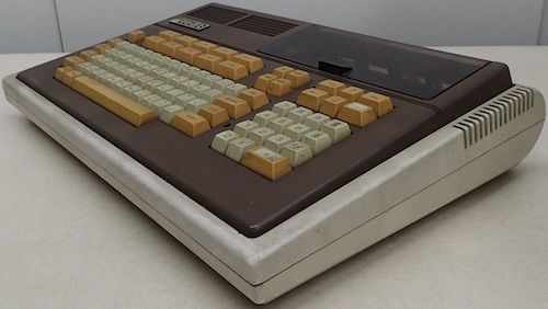
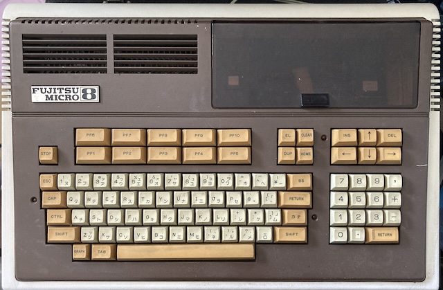
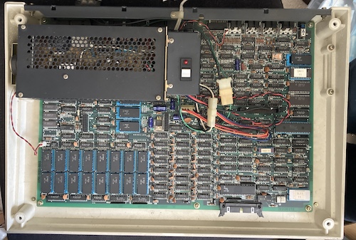
Here is the FM-8 as it was photographed at auction. It looks a little grungy, but it’s not that bad overall.
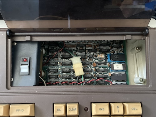
Why was it so cheap? This is why:
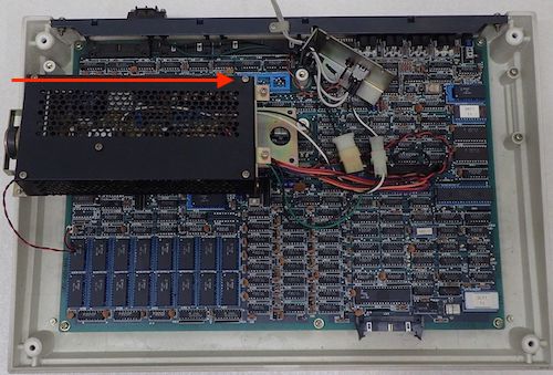
The CPU is missing! Not both of them, just one of them – the main MBL68A09!
It Wasn’t A COMPACkage Deal
Why isn’t there a CPU? One obvious reason is that it’s been parted out. Blog friend Frio found that the same seller (yugen2plus) also, coincidentally, had a Fujitsu FM-8 CPU accelerator board (“HERO-09 (by) COMPAC”) listed shortly after it. This board slots into the CPU socket using an IDC DIP connector.
The ad fesses up to the brain surgery:
Removed from FM-8 being exhibited at the same time.
Wanting to reunite them, I bid on that board, but didn’t win it, as it went for ¥9000, way more than the ¥2900 of the FM-8 chassis itself. Let’s take a look at the auction photo of that accelerator board:
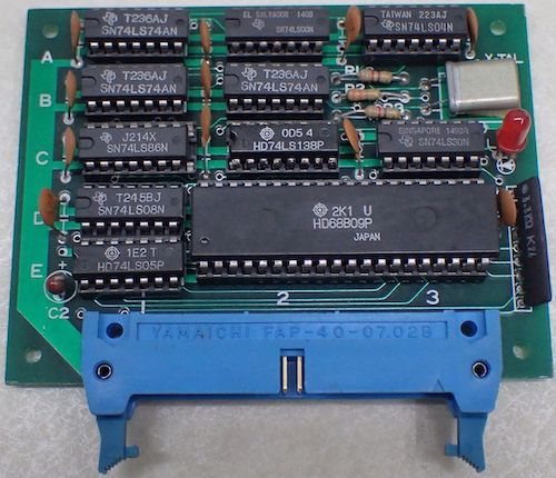
The presence of a separate clock crystal and some flip-flops seems to indicate to me that the CPU is being run at a much higher clock rate than before. Indeed, the ad describes it as a “double-speed” board. All of this support circuitry must either synchronize it with the slower system bus, or add wait states; it’s a little bit above my pay grade at the moment.
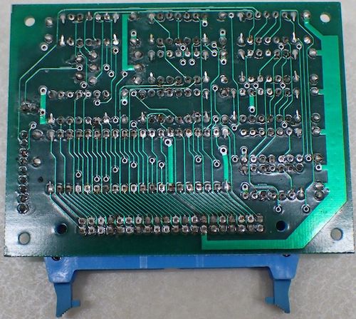
In my research, I found that the October 1982 issue of I/O magazine published an article describing how to build the HERO-09 accelerator board at home, written by TAKAYA Kasasaku1. This seems to be a pseudo-commercial version of that board, made by COMPAC. Judging from the solder joints, it was probably made in low quantities and by hand. There are lots of other speed-up boards for the FM-8 out there, as well as fancy video boards and other hobbyist shenanigans. It’s great that websites like this listing of accelerators still exist, and offer a glimpse into the history of a relatively niche computer. Even Artdink – my Artdink?! – made a bank-switching board to expand the memory.
Speed-ups were popular: this machine’s performance, as we’ll find out later, is absolutely glacial. Blog superfriend Nicole even set up her proprietary nya™ BASIC benchmark that shows a stock FM-8 is even slower than a Sega SC-3000 at printing large quantities of scrolling text.
Fascinating – and I think this deserves a journey into making a modern, open-source replica of the HERO-09. However, it would be silly to spend a lot of time making a clock-doubler board for a computer, if the computer doesn’t even work.
Brain Transplant
In order to test the machine, I reached into my drawer of CPUs and pulled out a 63C09EP. This CPU is a Hitachi-made hot rod, essentially identical to a 6809 until its secret alternative mode is activated. That mode is so secret that Hitachi’s engineers didn’t bother mentioning it until a few years later, when the info was published in magazine Oh!FM in 1988, and later distilled to an English-speaking audience by Hiroshima University’s Hirotsugu Kakuga on the comp.sys.m6809 Usenet group in 1992.
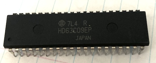
What kind of features does this secret mode unlock? Extra registers. Of course, there’s lots of other bonuses, too, such as fewer cycles per instruction, block transfer instructions, and hardware multiplication, but “finding some secret extra registers” is pretty far up the list of good things in the world. They also seem to be able to tolerate a much faster clock than the 6809, which is why they’re a popular upgrade for the Tandy CoCo3.
However, I wasn’t not planning on doing any of those fancy upgrades, either. All I want is the regular old 6809 mode, at the original 1.2MHz. Turns out that was going to be harder to get than I thought!
Open It! Open It!
Soon, the FM-8 arrived, and it was unexpectedly grungy. I gave it a quick wipe on the case with a Lysol wipe, and that took care of a decent portion of the gunk. I assume that this is all storage gunk, as the inside of the FM-8 looked too clean to have been used in an industrial setting.
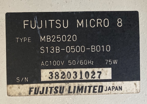
I haven’t been able to find a decoder for this “type” designation, so I’m not sure what this computer came with from the factory. The serial number is pretty funny; although this machine was popular, I sincerely doubt Fujitsu sold nearly 400 million of them.
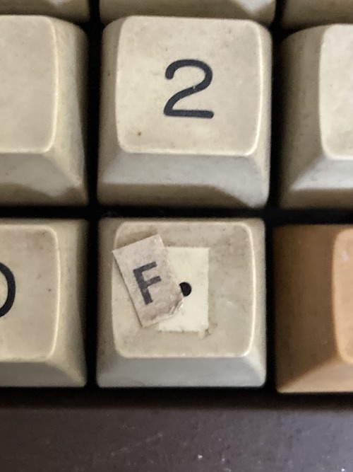
While cleaning, I noticed that there were letters “A-F” on stickers stuck onto some of the number pad keys. I assume this was for some kind of hexadecimal input, maybe an assembler or machine monitor. Between the HERO-09 and this, it sure seems like this computer got used for fun stuff.
The Fujitsu FM-8 is a massive computer. I sort of expected it to be about the same size as my already-large FM-7, but it’s at least another quarter as large in each dimension. Here’s a Game Gear for size comparison:
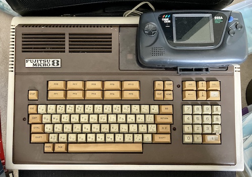
Okay, let’s get it out of the way now and check out what’s under the Game Gear: that tantalizing smoked-plastic door.
I do so love a compartment.
As you can see, the door on top of the machine has nothing under it. Normally, this is where an expansion (such as the bubble memory) would go. Based on my limited research, machines without an expansion had just an empty space-filling cup here, often colloquially referred to as “the ashtray.” The seller left the screws that mount this ashtray behind, which was nice of them. There’s an IDC expansion header on the motherboard underneath, which I’m sure we can fill up with something good.
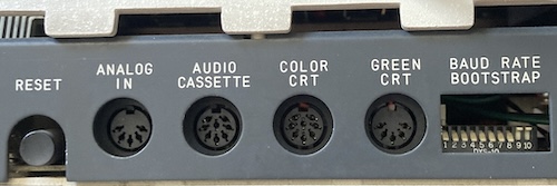
The ports are pretty straightforward, except the “analog in” connector is a little mysterious. Turns out that’s for reading any analogue data source, such as Apple II-style joysticks. There is support in BASIC for quantizing them, and presumably some kind of simple internal ADC to read them somewhere in the maze of passives around that port. That’s a cool addition!
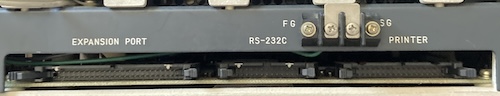
Of particular note on the right side is that “FG” and “SG” are broken out separately. This made me suspect that “SG” was for the shield ground of the RS-232 cable, which should not be connected to logic ground.
Despite the fact that the computer had been opened recently, the screws were very tight. I think they probably used a power tool to close it up again. Thankfully, the computer has brass threaded inserts for the screws to go into – this thing must have cost a fortune, as the screw pillars are even reinforced! It must have been a huge job to injection mould the massive case, as there are multiple injection and ejection marks on the bottom pan.
Once the four screws holding the top on were removed, I had to remove the keyboard cable so I could pull the top off. Keeping with the high-quality standard, this is an IDC ribbon cable. It’s a little bit short, which is annoying to manuever, but I’ll take that any day over fragile membrane ribbons from the 80s. Top notch.
With the motherboard exposed, it’s worth taking a moment to admire the vast quantity of ICs on this puppy.
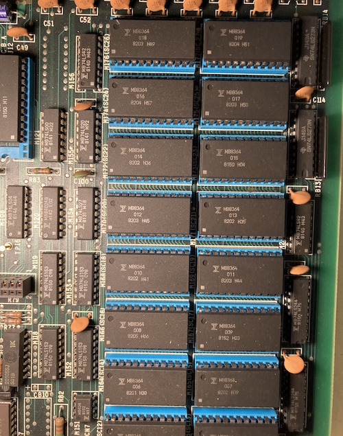
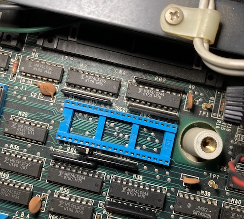
There is an entire bank of sixteen 64kBit MB8364 ROMs here! And they’re all socketed!
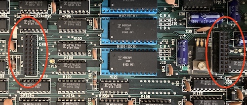
There is also this intriguing pair of expansion headers near the ROMs. On the FM-7, this pair of connectors is used for a sound expansion. On the FM-8, almost all internal expansions used these connectors, because this machine lacks the nice expansion card slots of the FM-7. Maybe a Z80 card could go here, if one were to be invented? Hmm.
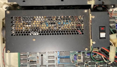
The CPU, or, to be more accurate, the CPU socket lies underneath the big black power supply. The speaker is bolted to the side of the power supply, and points inward rather than outward. Maybe that’s so they can minimize how loud it is? I looked around and found four screws holding the power supply to the bottom pan, but had to remove the main power switch first to get at two of them.
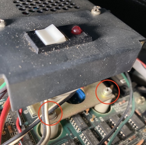
For some reason, Fujitsu put the main power switch under the expansion door on the top. You have to flip the lid to flip the switch, which makes some sense. However, as you can see, the switch plate blocks the screws that hold the power supply to the bottom pan, so I had to remove that first. Inside the switch plate is a switch, a mount for a power LED, and a fuse holder, and it passes 100VAC to the rest of the board through a Molex-esque connector which was incredibly seized, so I decided to leave it alone and just move the whole assembly aside.
The screws holding in the power supply were of mismatched lengths, which doesn’t bode well, but the threaded inserts were more than deep enough to accept the longest screw.
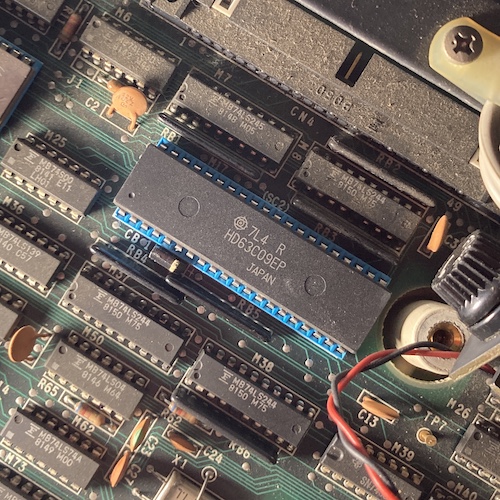
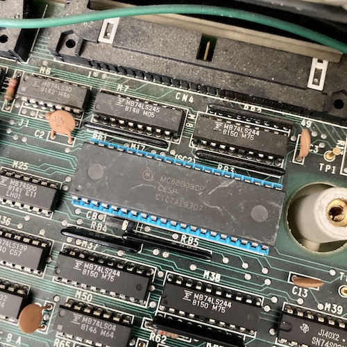
At last, the power supply was out of the way, and the CPU socket was exposed. I’m a little confused why this is labeled “SC2,” and thought it might actually stand for “sub-CPU,” but the other CPU was labeled “SC10,” so perhaps Fujitsu’s IC-numbering person took a day off on this one.
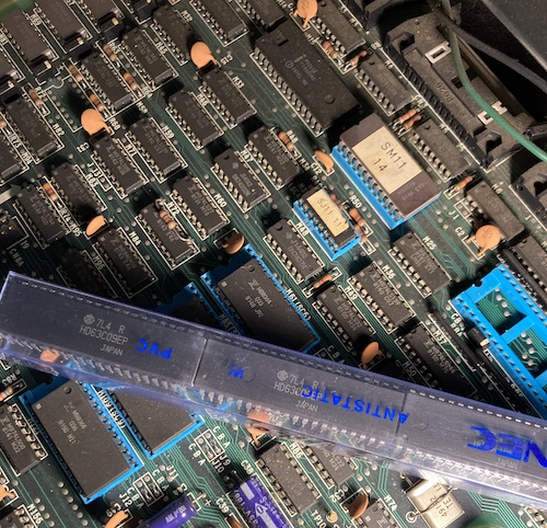
I pulled out my sleeve of AliExpress-salvage 63C09EPs, and started preparing one for insertion. The CPU socket has such a narrow opening that you have to get the pins really straight for a clean insertion. It took a few test fits and re-tries with the IC pin straightener until I got it, but finally the new heart of the machine was seated home.
After reassembling, it was time to try it out. Right after I cleaned the desk enough to find a place to set it up. I decided to procrastinate on that task, which turned out to be fortuitous.
You see, I had just put the wrong CPU in!
A Lesson In Reading The Labels
The 6809 comes in two varieties: 6809, and 6809E. If you look very closely at the picture up above, an HD63C09EP is being inserted into the socket, and if you look closely at the HERO-09 picture, a non-E HD68B09P2 is what was originally being used. I had these 6809E-compatible chips on hand to do a Tandy CoCo upgrade in the future.
What does the “E” stand for? 6809Es require an External clock generator. Non-E parts generate their own clocks internally (using an external crystal, of course,) which is a pretty neat trick for 1978. Of course, this discrepancy means that the pinouts are not compatible, and these two parts are not interchangeable besides both being 6809s.
The Fujitsu FM-77AV2 I’d been struggling with at the time used an 6809E variant for its main CPU, too, so I didn’t even think to check if the FM-8 also did. Luckily, blog friend Curt noticed from the pictures that it was the wrong part. I opened the machine again and pulled out the HD63C09EP with a chip extractor.
Try, Try, Try Again
I ordered a non-E HD63C09P from AliExpress, and waited patiently by the mailbox for it to arrive.
What else should show up after several weeks but another 63C09EP?
So I went nuts. I ordered 6809Ps from two more sellers. One of them sent me a pack of ten “68B09Ps,” which were actually:
- Three 68B09EPs;
- Two 6809Ps;
- One 68B03P (how’d that get in here?);
- Four 68B09CPs!
Hooray! At last we have a non-E 6809 to put in this thing. I checked around but I couldn’t figure out what the “C” designator meant, other than perhaps higher temperature for industrial use. I’ll take it.
The chips looked very dinged up, but I prefer that to the fakey remasked ones that many AliExpress sellers offer. It’s especially annoying when they add solder to the chip legs to shine them up, and end up making them harder to bend and more likely to snap.
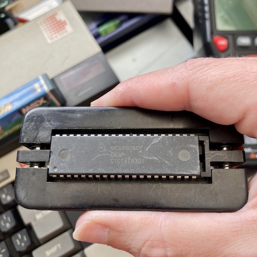
I squeezed the legs of an MC68C09CP in my chip leg straightener so it would be easier to insert, and then I dropped it into the socket. The only drama involved was having to back the screws off on the power supply, so that I could wiggle it around to get a better angle on the mounting posts.
I’ll have to find something to use all these other CPUs for.
Hello Major FM-8, Are You Receiving?
I’ve been told that the FM-8 video pinout is identical to that of the FM-7, which means it’s identical to that of the PC-8801mkII3. And that’s really good news for me, because I have made a PC-8801mkII video adapter before.
I powered the computer up. The ceremony of flipping up the expansion-ashtray door to hit the main power switch is kind of fun.
Sync! Video! Unfortunately, the video was just a blinking insertion cursor in the top left. It was followed by a shrill beeeeeeeeeeep from the speaker. Something wasn’t right.
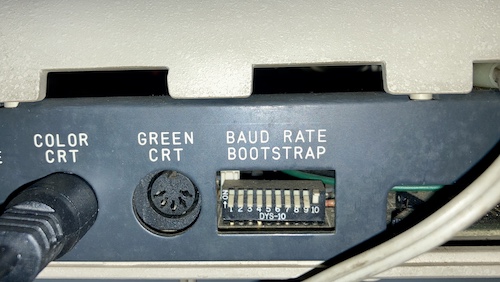
I suspected this row of dip-switches on the back, labelled “BAUD RATE/BOOTSTRAP.” Out of laziness, I decided to flip switch number 10 back down to match the others. This made the beep go away, but there still wasn’t anything happening on screen.
After annoying everyone I knew who knew things about FM-8s, I eventually did a search and found blog friend Sean’s post about his FM-8. He was gracious enough to have taken a picture of the back of his computer, where switches 9 and 10 were flipped up. So I did the same.
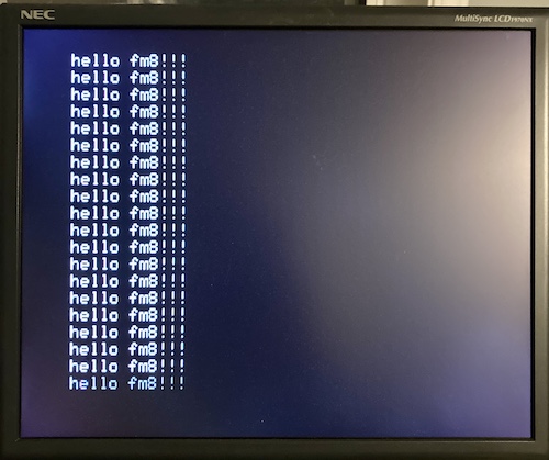
Now, after some hesitation, Fujitsu BASIC was launched and a program was entered. This is a very nice keyboard, possibly because it’s built like a brick shithouse, just like the rest of the computer.
If I had been a little more patient, I would have been able to look up blog friend Curt J. Sampson’s knowledge base about the Fujitsu FM-8, which would have told me to put up switches 9 and 10:
| Switch 9 | Switch 10 | Does what? |
|---|---|---|
| UP | UP | F-BASIC ROM/disk mode |
| UP | down | Bubble memory |
| down | UP | DOS |
| down | down | Reserved/unused (or 8” DOS?) |
Take the ROMs to the PROM
Something was still bothering me. Maybe you noticed it in one of the previous pictures. The ROM closest to the CPU isn’t a mask ROM, like the other ones on the motherboard. No, it’s a UV EPROM. If there were other modifications done to the system, then maybe the person who had it before put something cool in ROM! So… what’s on that ROM?
I did a little bit of poking around and found two plastic-package EPROMs: SM11-14, and SN11-11. According to Retro PC Gallery, these are the stock Fujitsu 5.25” floppy BIOS and the font ROM, respectively. I also found a ceramic package chip with a sticker, which I’m also assuming is an EPROM, marked SL11-11, and what appears to be some kind of small PLD or bipolar PROM, SK11-11. I wasn’t able to find any documentation on these parts, but I’m assuming they are all stock.
So, no new cool software, but it’s fun to look at how many ROMs this considerably expensive machine held. If I am understanding other sources correctly, then there is some kind of ROM-resident Forth out there that I would like to try and get running on this machine in the future.
In the meantime, this FM-8 is running, and it’s ready for all kinds of other shenanigans. I have a couple things I would like to explore:
- The software catalogue, including the few games made available for it;
- Disk drive interfaces, maybe even an emulated one;
- Implementing the HERO-09 clone. I’m pretty sure we can build one for less than ¥9000 plus shipping, even if we do need to buy an IDC DIP connector.
Repair Summary
| Fault | Remedy | Caveats |
|---|---|---|
| CPU is missing. | Put the correct 68B09P CPU in. | Do not put in an “E” CPU. |
| Does not boot after CPU replacement. | Change bootstrap DIPs 9 and 10 from “DOS” to F-BASIC ROM (UP/UP) |
-
There appears to be an article later, in the June 1983 edition, where they discuss fixes for floppy drive compatibility when using the HERO-09. The HERO-09 introductory article is reprinted in the FM-7/FM-8 Application Note mook, as well. ↩
-
The “B” indicates a higher clock speed than the standard issue. According to the Hitachi HD63B09 datasheet, the “B” part is good to 8MHz, unlike the “A” part which is 6MHz, and the unmarked part which is 4MHz. ↩
-
Tons of Japanese computers use this pinout for TTL-level RGB, making it almost a de facto standard in my book. This might be the most useful piece of hardware I’ve ever made. ↩