A mystical journey to PC8801mkII colour video
Tags: computer nec pc88 pc8801mkii video retrochallenge retrochallenge-september-2018 homemade-hardware
I’ve been using the monochrome video cable on my PC88 ever since I built it. Colour video was a little more complicated, so I ended up designing a bunch of adapters to try and get it to work. I’m happy to announce that one of those adapters has finally worked!
Theory
NEC apparently didn’t think the PC88 needed vibrant colour, so for the pre-SR models (like my mkII), they didn’t bother adding it.
What they have apparently done from the PC-6001 on upward to the 8001 and 8801 series is do digital RGB colour. In case you’re not terribly familiar with the idea (I wasn’t), here’s the concept as far as I understand it.
In this digital-RGB implementation, red, green and blue are either all the way on (logic level high) or all the way off (logic level low). This means that you only have 23 = 8 colours to play with, but with dithering and crappy CRTs, that’s probably enough. Hell, it’s six more than the period Macs got.
Unlike CGA, it doesn’t have an intensity bit, which would double the number of possible colours (by toggling between “dark” and “bright” versions of those colours). Lots of other 8-bit computers used this “RGBI” digital video, including the Commodore 128, so I’m not sure why the PC88 didn’t bother.
On the 8801mkIISR and better, which came immediately after my computer, NEC decided they needed to display more colours than just 8. The “V2” graphics mode added on those later machines allows them to pump out any 8 of 512 colours. You, the programmer, get to choose. These machines use the 15-pin Japanese-style “analogue RGB,” like my PC-9821AP2 does.
Okay, enough about the theory, let’s move onto the hardware.
Building the adapter
After looking around on the Japanese internet for awhile, I found a pinout (at the always-helpful Nishida Radio). My first idea was to make it use the “CGA” pins on the cheapo GBS8220 upscaler I had lying around, but then I stumbled across an implementation of the design that just used 150 ohm resistors on red, green, and blue to force them from “TTL” level down to the voltage level that VGA understood.
The pinout is supposed to be the same for a lot of other computers, such as the Fujitsu FM-7, but I haven’t tested it yet.
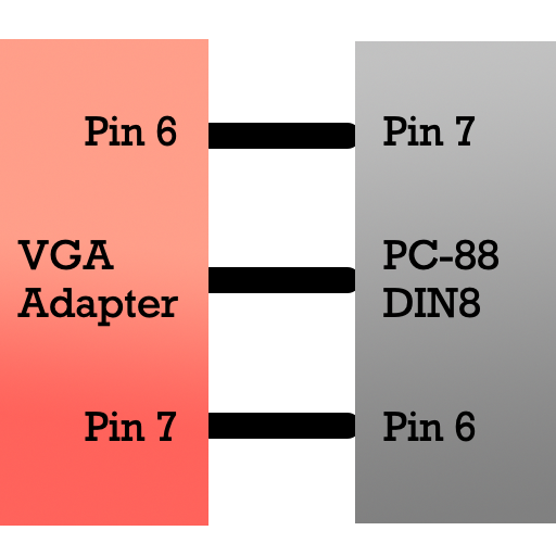
Update: The previous version of this pinout uploaded had the colour pins flipped horizontally and was thus totally wrong. Thanks to Curt J. Sampson for pointing out! This version is correct as measured from my working adapter:
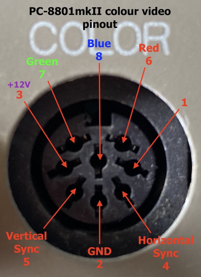
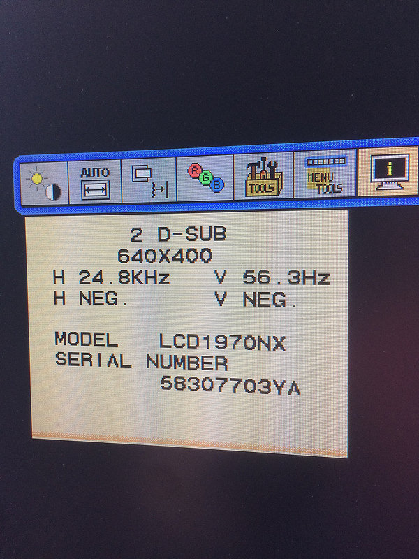
Paired with a 15/24kHz-capable monitor, like my trusty NEC 1970NX, this would be enough to put sharp colour video on the screen.
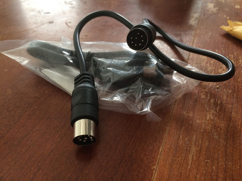
One big problem was going to be making an 8-pin DIN cable. I had enough trouble trying to make 5-pin DINs for both my C64 and the monochrome video cable for this machine, and I dreaded having to do even tighter-quarters soldering work.
Luckily, after a few weeks of hunting, I found an Ancable male-male 270° DIN8 cable on Amazon. It was short, and it was cheap enough that I could cut it up and make pigtails if it didn’t work out. According to the seller, the cable is actually intended for a “Peavey Sanpera” guitar pedal, so if you have one of those pedals lying around you’re good to go.
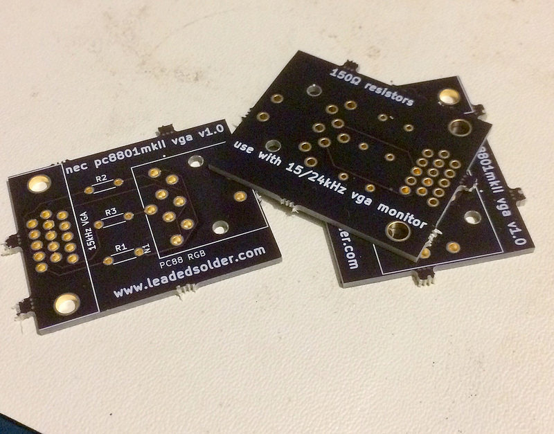
Board version 1
I put together my first version of the board, sent it off to Oshpark, and waited a few weeks. When it got here, it didn’t work. I tried adding some patch wires, thinking I had gotten the H-sync and V-sync lines backward, but all that did was make the monitor wake up and recognize a video signal, before again returning to “no signal” status and turning itself off. What happened?
A short digression for those of you unfamiliar, as I was, with how you buy electronic components to assemble logic boards. When you lay out a PCB, tools like KiCad use a “footprint” to figure out how big to make the holes, how to map pin numbers to holes, that kind of thing. If that footprint’s wrong, the resulting board is either not going to fit the component, or it’s going to be wired up incorrectly.
In my case, despite getting the footprint from the actual vendor of the connector, it was backwards both side-to-side and front-to-back.
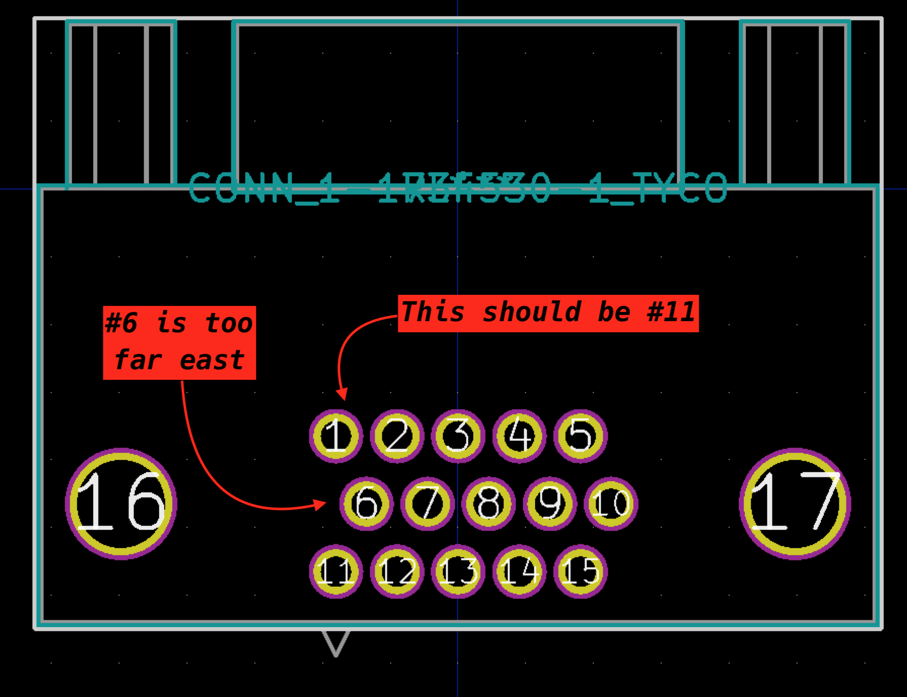
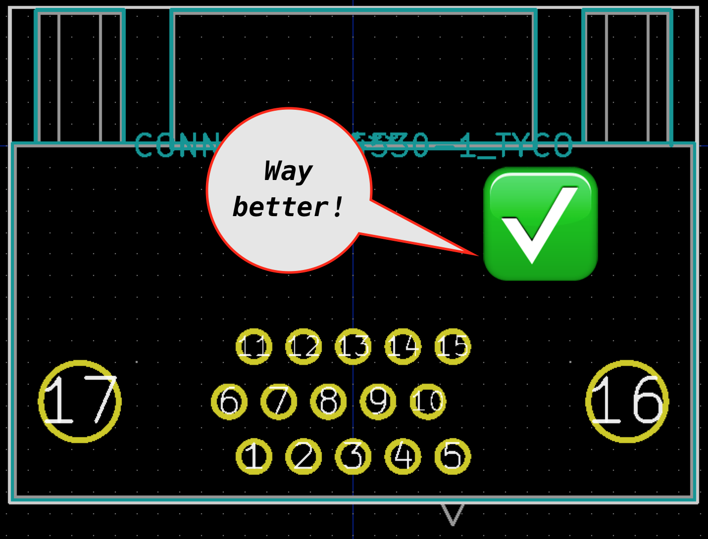
I ended up manually editing their footprint and printing out a few copies of the board on paper (like a caveman) to make sure the pins actually lined up and that they were mapped to the correct pins. It’s amazing how much sending signals to the right places matters.
While I was in there, I also flipped the DIN connections side-to-side, after realizing that if a female DIN faces a female DIN, they were going to have to be mirror images of each other - not straight through.
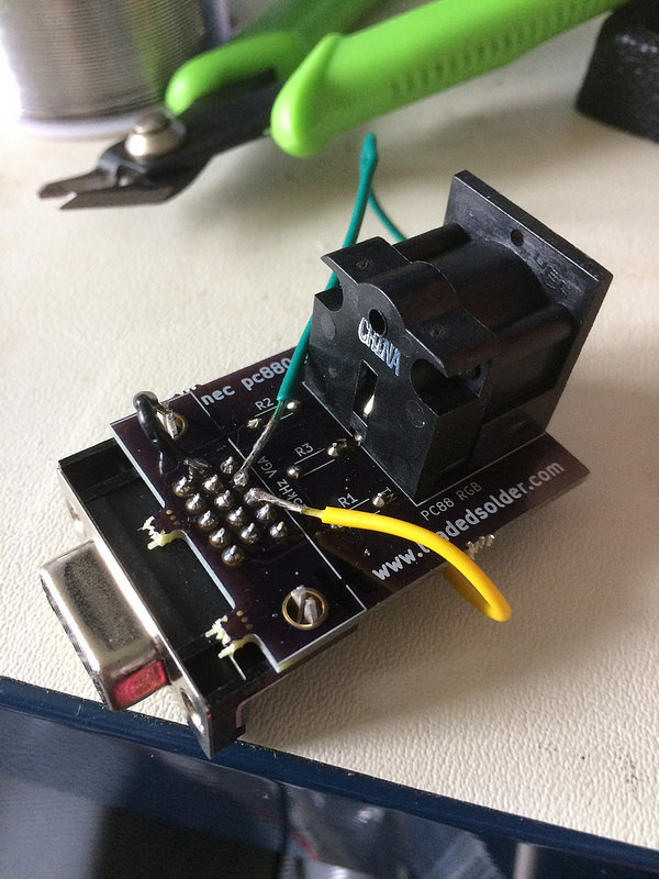
Board version 2
Another board arrived quickly from AllPCB, and I went to work putting it together. Everything went together great, and then I fired it up.
Blank screen.
I dimly remembered that when I put together the composite cable, I was initially confronted with a black screen, and had to move the resolution jumper from “high” to “low” in order to get anything to display. Could this be the other way around? I reset the jumper and started the computer again.
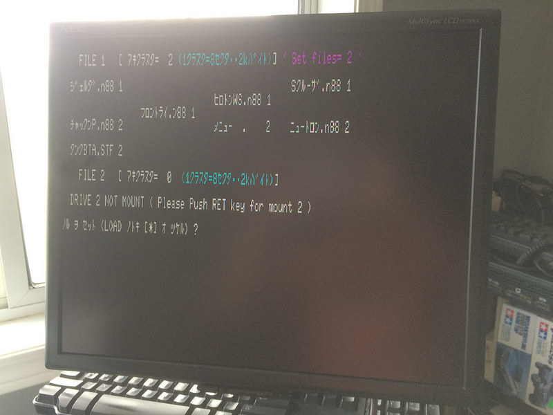
IT WORKS!
As documented, “high” mode runs in 24kHz horizontal refresh. Most monitors, and especially most LCDs, can’t do a refresh rate this low (VGA usually uses 31kHz), as Amiga and Atari ST owners know all too well.
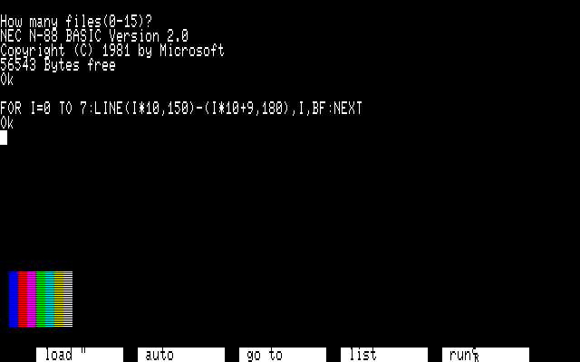
I immediately restarted into N88 BASIC and ran a one-liner to make sure that I did actually have the colour mapping working properly. According to a screenshot on Wikipedia, this is what you should get when you run the one-liner:
After a few typos, I ended up with my own version:
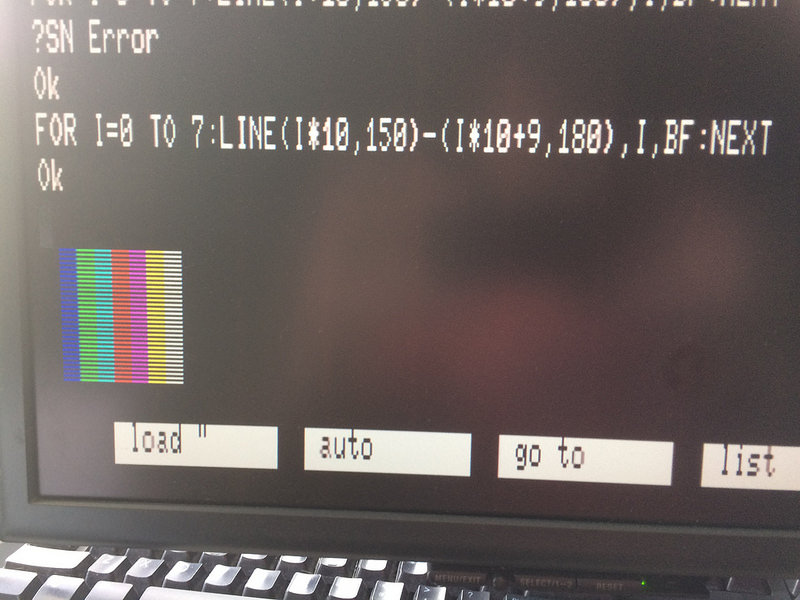
In case you’re colour-blind or just skipped your coffee this morning, here’s the problem. Red and green are swapped - I mixed them up coming off the DIN. Somehow I managed to screw up colour but not horizontal/vertical sync when I was copying Nishida’s diagram.
Not to worry - I left enough room to get in there and bodge the whole thing. After soldering in some resistors with really long legs, I was able to confirm that I had indeed mixed up red and green.
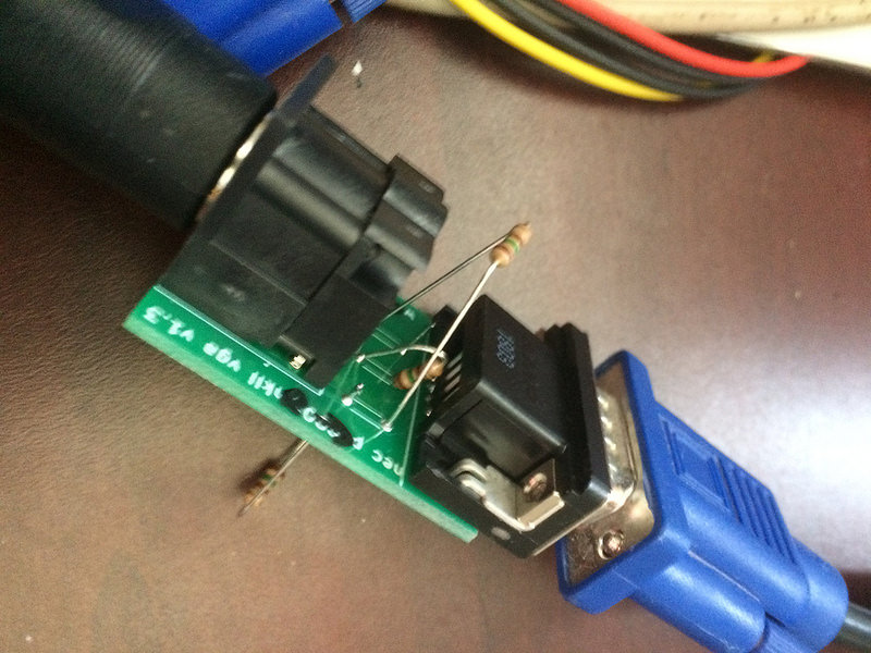
Why did I not just put red and green next to each other on the board? Uhhhh, next question please.
After bodging, the colours now matched that of the Wikipedia one-liner:
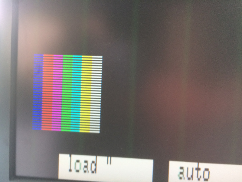
You’ll notice some green vertical bands there, which are probably caused by the very long resistor legs now picking up some interference. I’ll live with that for now, but I might experiment with shielding them if I get particularly bored.
Next steps
I actually accomplished all my goals for a RetroChallenge and still have just about a week to go. Maybe next time, I’ll have to invent cold fusion, or build a whole computer from sand. I’m definitely no Nintendo horse betting system reverse-engineer, or native Forth machine Verilog abuser, but I had a lot of fun with this relatively simple little machine.
I’ve already sent out for a “version 3” of the board, so hopefully that will be good enough for public consumption soon. A few people have already expressed interest!
I did a bunch of other stuff with the PC98 while I was waiting for parts, so there’s another blog entry coming this week on that subject.
You’ll remember that when I first got this little mkII, my goals were simple: I wanted to learn about the platform. I think with the having built a monochrome video cable, floppy disk adapter, and now a colour video adapter, I now have a pretty good handle on the PC88 platform and have to set my sights higher. Perhaps I can even track down a technical manual of sorts, and build an expansion card for this little machine!
I’m also interested in getting an 8801mkIISR or better for my next Japanese NEC computer. While I’ll have to make another video cable for that, at the very least there are a lot more games, and my expensive keyboard will also work with an SR.
Update: The green interference lines turned out to be an artifact of my monitor’s scaling logic. After I noticed it in a PC98 game, I tweaked the monitor’s horizontal scale and fine adjustment until they were no longer visible. When I tested on the PC88, the vertical lines were gone.
My favourite kind of fixes are the free ones, or at least free unless you value your sanity.