Building my own mechanical keyboard for the CoCo 1
Tags: computer tandy trs80 coco keyboard homemade-hardware
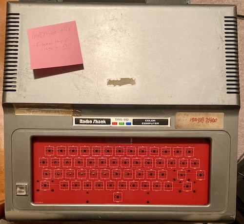
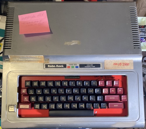
Yep, it finally happened. The backwoods repair that I did to my Tandy TRS-80 Colour Computer’s keyboard membrane failed. Turns out that garden-grade self-adhesive copper tape and some electric paint is not a lasting replacement. Let’s do something that will last a little longer.
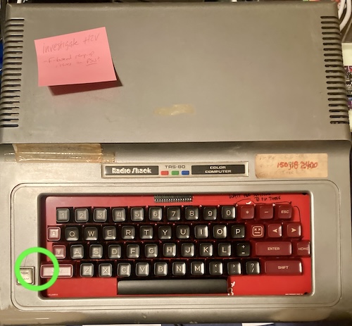
In case you’re new to this project – welcome! – this TRS-80 Colour Computer is one of the first machines that I acquired for the purpose of repairing. Someone on Reddit was getting rid of it after finding it in a waterlogged shed, and I stuck my hand up. Naturally, there was lots of dirt, nature, and other gunk inside the machine.
After getting the computer to boot, I realized that the keyboard didn’t work very well. Inside the keyboard, the plastic keys rest on sliders, and those sliders pinch a mylar keyboard membrane, which acts as a sort of flexible circuit board. These membranes are very inexpensive to make in large volumes, and usually very reliable, but after nearly forty years, this one was starting to fail and had a bunch of broken traces.
The original concept
In other words, my CoCo1 showed up with a largely non-functioning keyboard. It seemed like it would be a lot of work to patch it up with paint, and copper tape, and jumper wires. Chances are it would be less work to simply replace the finicky membrane with more durable mechanical switches.
Back then, there weren’t many options for this. The CoCoMech existed, and that was all I could find. It’s a super-high-quality drop-in replacement, solves all my problems. Unfortunately, it cost $120 USD plus shipping, which was a little too much money to invest in a CoCo1 that got dug out of a shed flood. And it was out of stock.
I decided that any PCB would need to use common keyboard-hobbyist parts in order to keep costs down. I can do this because there is a huge (and growing?) Chinese supplier market for mechanical keyboard hobbyists. I can pick out switches and high-quality injection-moulded key caps, and take advantage of software, datasheets, and other knowledge the community has already figured out to do this - ideally - cheap and fast. Why reinvent the wheel?
First, I decided that I would try just making a frame to hold key switches in mid-air, and then run wires between them for the matrix. Somehow, it seemed like less work than a PCB, and I wanted an excuse to play with OpenSCAD and 3D printing.
Version 1: does a frame even make sense?
Originally, I wanted to write some code in OpenSCAD to generate this keyboard frame. I’m generally unfamiliar with CAD software, and so being able to write code to line things up instead of fiddling with the mouse appealed to me. It’s a pretty good package if you’re “dimensionally-challenged” like I am, though I am definitely still doing more Googling than drafting. I wrote a few little modules to generate the special “Cherry-mount” holes, and then fiddled around for a good hour until I had something that looked alright but not great.
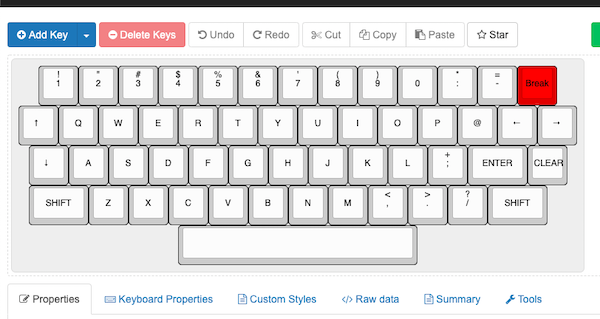
Then I found out that there was just a tool that would generate plates for you. It’s called Plate & Case Builder, and the best part is that it takes keyboard-layout data from the excellent Keyboard Layout Editor web-app.
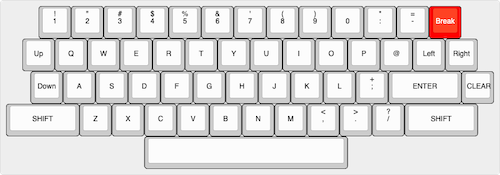
I decided I would stick to the original TRS-80 CoCo keyboard layout, if for no other reason than I had no better ideas. It wasn’t completely straightforward, as I had to change the space bar out from the original “8u” width (i.e. 8x the width of a normal, “1u” key) to a 6u, which was much easier to find keycaps for from eBay/Aliexpress thanks to the growth in 60% “Poker” or “GH60” keyboards.
It took about 15 minutes to make this CoCo keyboard layout in the cool GUI editor:
And then I quickly imported that raw layout code into the Plate & Case Builder:
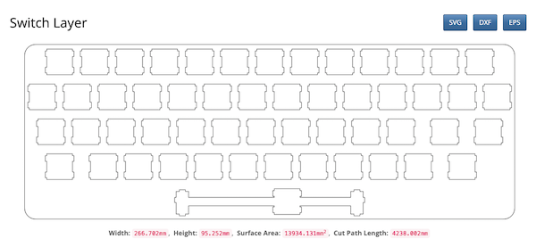
And then it spat out a DXF file, which included a hole to stabilize the 6u-wide space bar.
If I had a laser cutter, this would be the end of it. I’d just feed in the 2D DXF information, cut it out of some handy-dandy 1.6mm metal (Cherry says 1.5mm ± 0.1mm is best for plate mounts) and wait a few minutes while my house filled with the odour of CO2-powered incinerated metal.
However, I only had access to my brother’s 3D printer, and as that is virtually free - family comes first, right? - I figured it was worth doing a little bit of additional work to send it out of that fancy robotic glue gun. I extruded the 2D DXF to a 3D STL file, using OpenSCAD:
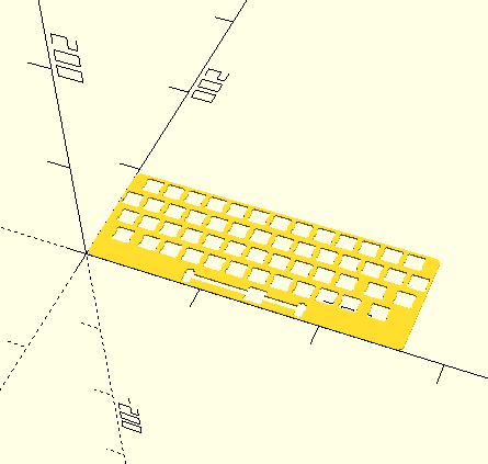
Unfortunately, the printer only had an 8x8cm bed, so we ended up chopping the model in half. While this wouldn’t be great for production, I figured I could at least work out whether or not the switches even fit in the frame.
And then we set about making the printer do all the hard work. Pop a window, because that stuff stinks.
That didn’t come out the way I expected. The first run, whether because of old ABS filament (it picks up humidity in storage) or because of some freak micro-earthquake, more closely resembled black plastic vomit than it did a working keyboard.
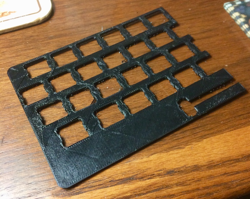
This, the second run, didn’t come out too bad. After trimming the raft away, it looks like it could be workable.
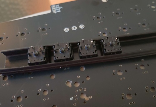
Although I didn’t have any plate-mount stabilizers on hand to test the spacebar, I decided to try and test-fit some of the Gateron switches from my parts bin…
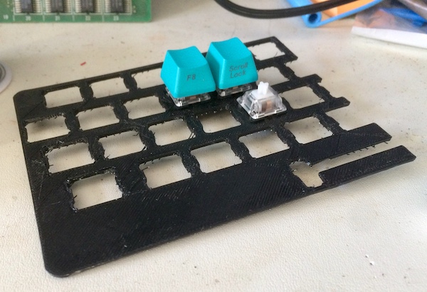
Looks good. This might just work out after all! The plate did distort quite a bit when the switches were being loaded, mostly because it was very thin ABS plastic. I reckoned that I would have to add strengthening ribs or make a much thicker plate, in order to have decent typing feel, instead of “moist serviette.”
Then, after all this, I decided not to go through with it.
I ended up being able to fix the membrane in 2020, and bailed on this entire project in favour of playing videogames on the CoCo instead.
That is, until I took the CoCo back out of storage in 2024, and found that the membrane had failed once again. Now you’re all caught up.
Version 2: You know what? Let’s just do a PCB.
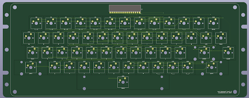
In the intervening years, I’ve gotten slightly better at PCBs. Nobody is going to say “a lot better,” because that’s a lie. Tools for building keyboards have actually gotten a lot better, though: a very cool tool called klepcbgen can import the Keyboard Layout Editor files and generate an entire KiCad project for your keyboard.
I rebuilt the keyboard in Keyboard Layout Editor. This time, I made sure to also pick key spacings that made sense for key caps I could actually get: 2.25u for shift, 6.25u for space bar, that kind of thing. I ended up with an altered, but still recognizably CoCo, layout.
Since klepcbgen is meant for a hobbyist keyboard community, it makes some assumptions that aren’t helpful for my needs. Primarily, the tool makes a very simple “grid” keyboard matrix, with rows and columns corresponding to the physical rows and columns, and wires it up to at an Atmega. I had to rewire the matrix to fit with the CoCo one, but that only took an hour or so. Last, I needed to do some dances in KiCad to “re-establish” the relationship between the schematic symbols and the footprints on the PCB file, but this was all documented in the wiki.
klepcbgen also inserted surface-mount anti-ghosting diodes, which I decided I didn’t actually need. The original membrane didn’t have them, after all. Now, if it had inserted RGB LEDs, that would have been a whole other matter…
The primary benefit of using klepcbgen for this part of the project is that it took care of all the monotonous placement of the footprints and symbols. Now, all I had to do was take care of the monotonous measurement of the keyboard frame itself.
This time around, I chose to build the keyboard in the outer structure of the original plastic frame. It would be sunk down fairly far in the case compared to the original keyboard, but I could always add a plate or something to help smooth it out later.
I ran into an unexpected problem when I went to print out the PCB in order to test fit it. At 315mm wide, the PCB is wider than a single 279mm sheet of letter paper! I ended up using KiCad’s “plot” feature to plot to PDF, then cropping the PDF in macOS Preview.app, and finally printing it using the “poster” setting in Adobe Acrobat Reader. After some arts and crafts to cut and tape the two pieces of paper together, I could now test fit to make sure that my measurements were good. And they were!
After all of this physical-layer mess, actually laying out the PCB traces went relatively easily. I mean, it’s one of my worst PCBs ever, because I didn’t think about the route in any way other than “please make the ratsnest go away.” But it passed DRC, and that’s what it’s all about.
Building five of these keyboard PCBs cost nearly forty bucks shipped, which is steep but honestly not ridiculous for the size. I regret not having done silkscreen that was more fun, or at least pretty, but I was “on a roll” and didn’t want to derail this project any longer than I had to. You know how it is.
Testing Version 2
Waiting for the PCBs to arrive felt like an absolute eternity. Perhaps one day I will spend slightly more than “the cheapest possible shipping.” Or I could get sponsorship or something. Sponsors, go ahead and line up over there.
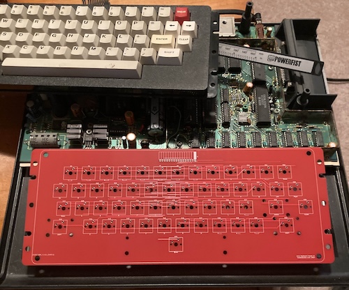
To my delight, it turns out that all that measurement and printing has actually paid off. The dry fit shows that the PCB mounts properly between the alignment pins, and leaves enough room for screw holes. I was very excited about this and immediately wanted to build it.
The top case looked pretty good too, other than two minor issues:
- The space bar sure seemed like it was going to get close to the bottom of the case. I decided I should move the switches up a couple mm, but I didn’t want to spend another $40 on another run of PCBs – I work around this later in the story.
- The two-dimensional PCB has significantly less structural support than the old three-dimensional plastic housing, so it slightly flexes and makes a vibrating noise when you type in the middle of it, where it’s not supported by any structure at all.
An unexpected problem came up: the connector. You can make the world’s fanciest CoCo keyboard, but it’s all for naught if you can’t electrically connect it to the CoCo! My CoCo1 has been modded so extensively that I have a couple different options for connections, including a male 1-row-by-16-columns 0.1” pin header.
Easy fix there, right? Just buy a 16-pin female DuPont connector, right? No! Apparently that particular configuration is kinda hard to find. I did find a fully pre-made cable at PCBoard.ca for $3.19, so I just bought that, even though it’s way too long for my purposes at 20 centimeters long. The website also offered this handy bit of info:
The DuPont crimp terminals are also known as Amphenol FCI Mini-PV compatible connectors.
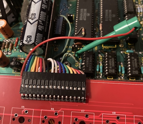
The more you know! The PCBoard cable harness showed up quickly, and did the trick. Ignoring my own silkscreen, I tucked the connector and the harness underneath the new keyboard PCB, giving it a little bit of a date with the hair dryer first so that it would take a bend.
The connector became a problem almost instantly, but let’s first look at some eye candy.
Bit-Shiftin’ Blues
The key caps also appeared at the same time. Let’s take a side bar to discuss the keycap plight for old machines before I show them to you.
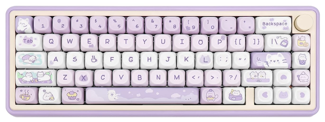
Virtually all keycap sets that are for sale right now use this kind of ANSI-style layout, where shift+2 produces @. Unless you live in Japan, you can look down at your hands and see a keyboard like this. As you might expect, that popularity is what drives demand for keycaps, so everyone makes them that way.
However, the CoCo, and a lot of other 70s and 80s machines such as the BBC Micro keyboard, use a different layout. This one goes by a few different names. ECMA-23 is probably the most descriptive one, but a lot of folks call it “bit-shifted.” Here’s blog friend Johnny Blanchard’s BBC Master to demonstrate:
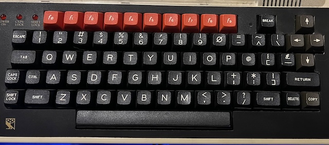
Why is it “bit-shifted?” Because it accurately names what happens to ASCII characters when the shift key is held:
| Number key | With shift (ANSI) | With shift (bit-shifted) |
|---|---|---|
1 (0b00110001) |
! (0b00100001) |
! (0b00100001) |
2 (0b00110010) |
@ (0b01000000) |
" (0b00100010) |
3 (0b00110011) |
# (0b00100011) |
# (0b00100011) |
4 (0b00110100) |
$ (0b00100100) |
$ (0b00100100) |
5 (0b00110101) |
% (0b00100101) |
% (0b00100101) |
6 (0b00110110) |
^ (0b01011110) |
& (0b00100110) |
7 (0b00110111) |
& (0b00100110) |
' (0b00100111) |
8 (0b00111000) |
* (0b00101010) |
( (0b00101000) |
9 (0b00111001) |
( (0b00101000) |
) (0b00101001) |
0 (0b00110000) |
) (0b00101001) |
0 (0b00110000) |
As you can see from the table, the “bit-shifted” format does nothing other than zeroing out the fifth bit of the character on the number row when shift is held down1. When you’re using ASCII, it’s a lot easier to calculate than the ANSI format, because it’s just an easy AND with a bitflag.
Like all bad things in the world, the change away from bit-shifted keyboards originated with IBM, specifically their Selectric typewriter series. I won’t go too much into the history of this, mostly because I don’t know all that much about it, but the long and the short of it is that I had to buy keycaps that don’t accurately reflect what character comes out when you push them.
Yes, there are some keycaps that have 2/", but most of them are UK layouts, which also don’t do things like 8/(. Believe me, I spent many evenings searching for any keycap set that offered bit-shifted characters. Eventually, I think the only way I’m going to be able to pull this off is with a custom-printed setup like that offered by WASD or Thock Factory. If you know of another, please let me know.
While picking out keycaps, I learned about the concept of a “profile.” In short, a profile is the vertical shape of the key. If you look closely at most any computer keyboard, you’ll notice that not all the keys are the same height. The QWERTY row, for instance, is a different height than the ASDF row.
Because the CoCo keyboard isn’t a conventional layout, I worried about getting caps that were different heights and looked bad. So I tried for a “uniform” profile family, where all the keys are the exact same height. For instance, the “XDA” and “MA” profiles are uniform ones.
Unfortunately, I couldn’t find a set that I liked. It seems like uniform-height keycaps are sort of unpopular, so I ended up with an “SA-profile” keycap set. While this keycap set has non-uniform heights, the heights are a lot closer together than on a traditional Cherry-profile keycap.
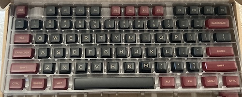
Here’s the keycaps I settled on, a $24 Canadian set called “Red Samurai,” in the SA profile. They’re a pretty good blend of old-terminal typeface with a nice splash of colour.
Because the inaccuracy of the legends bothers me – as clearly evidenced by the paragraphs, photos, and tables you just read – they probably won’t stay on the CoCo forever. But the price was right, and I think they look pretty cool.
Now let’s get back to assembling the keyboard.
Switches
As expected, I managed to get a good deal on switches. Originally, I was going to take advantage of a big sale at a small business, but their inventory cleared out before I was able to confirm if their switches would fit this board.
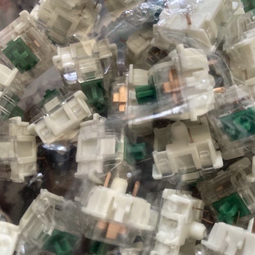
My choice was a Gateron green, mostly because it was cheap (just under $20) and it’s a nice shade of green. I have absolutely no rationale for this choice. If this makes mechanical keyboard nerds angry, please fight each other in the comments.
While I was waiting for them to arrive, I pulled some spare switches out of an abandoned XD60 keyboard and started shoving them into my prototype PCB. I was going to get a test.
First Test
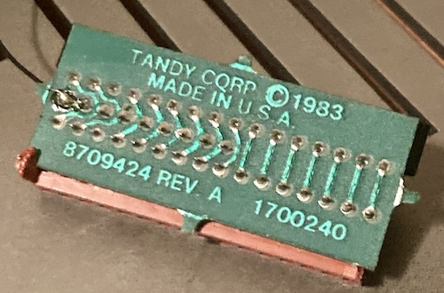
As I mentioned earlier, the connector was a source of much pain. On my CoCo, I had a little bodge board, labelled as a “Tandy 8709424 Rev. A,” attached to the pin header on the motherboard. This bodge board adapts the CoCo1 motherboard’s pin header to the plastic membrane of the long-throw CoCo2 keyboard.
I hadn’t paid it much mind, and just assumed I would remove and hoard it for later, plugging my glorious new keyboard right into the pin header. Unfortunately, as I was removing it this time, I realized it had something attached to it. Somehow I had managed to completely ignore the fact that there was a resistor network soldered in between, with a black wire running to TP12 on the motherboard.
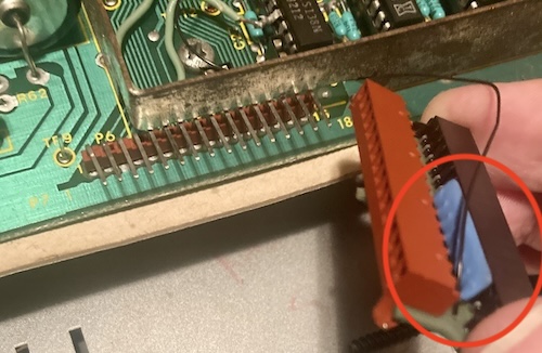
Yep - a nine pin, 4.7kΩ resistor network on the row lines of the matrix was apparently required to make a passive CoCo2 keyboard membrane work with this motherboard. The same passive membrane I designed my PCB around.
I grumbled for a bit, and then decided I’d just send it and see what happened. After some wrestling with cables, I fired up the CoCo with only the space bar switch populated.
Friends, I hit that space bar. And nothing happened. I hit it a few more times, just to be sure, but nothin’. Clearly this resistor network was important.
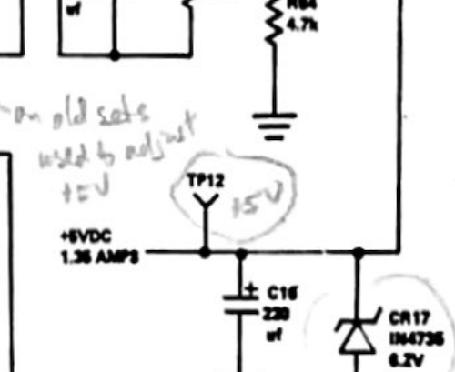
I had some questions at this point. Is connecting this to TP12 a pull-down or a pull-up? If it is a pull-up, what voltage is it pulling up to?
Poking around with my multimeter, I was able to find that TP12 was continuous with the Vcc pin on a nearby 74LS244. I assumed that was +5V, but I reached for the CoCo1 schematic just to be sure. It reassured me that it was indeed +5V.
It was at this point that I also realized my CoCo1 wasn’t running a Rev F motherboard after all, as I had initially assumed a few years ago. Not only are all the parts in the wrong spot, but the 8709137-E part number seemed to indicate something a little bit different was installed. It is a Rev E board, which doesn’t really mean anything to this particular project, but the placement of the chips might affect how I design the composite mod down the line.
I revised my keyboard PCB design to incorporate the fixes from the bodge board, but I sure didn’t want to spend another forty bucks. I made a quick bodge on the underside of the keyboard to add a 10kΩ resistor network of my own, copying the adapter. It’s very convenient that the pin spacing of the resistor network is the same as the connector, so I was able to just dead-bug it onto the bottom and then add a probe hook to a fly wire.
Now that I was pulling up the row lines, the keyboard should work! And it did, sort of.
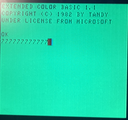
Whenever I hit the space bar, I got a 7. I’m not too used to the CoCo, but I don’t think that’s right.
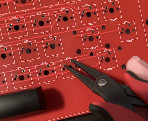
I decided to test the rest of the matrix, using my trusty Hakko pliers to short the contacts together. It turns out that most of the keys were right!
Enter the Matrix
Obviously I hooked up the space bar to the wrong pins of the matrix. An easy fix, right? Yes. I cut and bodged it to the correct pin, and now I had a working space bar. The same goes for the * key, which was bodged to the wrong column. A cut-and-splice fixed that one too. Now we were getting somewhere. Time to start putting switches in!
Population: Some
I ordered some Gateron “green” switches from AliExpress to serve as the majority of the keyboard. Unfortunately, when I got them, I realized that they didn’t have mounting pins on the side like my footprint expected.
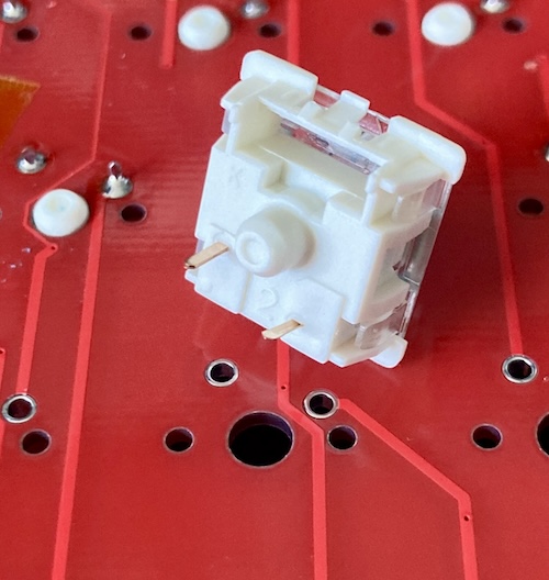
With only a single pin to mount them, it was hard to keep the switches exactly straight when soldering them down. A bunch of my keys still look slightly crooked, and it bothers me very much – but not another $30 set of switches much. It’s almost certain that this set is meant for plate mounting, or maybe even for some kind of funky hot-swap socket.
I have seen some kits that included a small “mini-plate” with room for only a handful of switches, and I hadn’t figured out what they were for until just now.
They are in fact a jig for holding this kind of switch in place so they’re not crooked when you solder them.
I did have a bunch of other Gateron switches with compatible mounting pins left over from a previous project, but they weren’t enough to populate the entire keyboard, and their feel is too different to the Greens. So for now, I’m dealing with individually reflowing switches when their grotesque misalignment bothers me. Heating up the joints and pushing them over a few millimeters to get them lined up does the trick. Lesson learned: look to make sure the footprint is exactly what I want – Gateron has much more variance in footprints than I expected, and “3-pin” is not the same thing as “5-pin.”
Notice how some of the red keys seem to “stick out” more than others? That’s the consequence of picking a non-uniform SA-profile keycap set. It’s not so bad when typing on it, but it sure makes it look weird. The crooked keycaps only slightly offset that jankiness but do not get rid of it.
These struggles are relatively small in the grand scheme of things. This first version is aiming for “working,” not perfect, because perfect never gets done. Soon, my ugly keyboard was coming together.
Mood Stabilizers
Now that I have most of the “1u” keys installed, it was time for the keys that are a little wider. The wider keys, such as space bar, shift, and enter will all wobble if you just put them on a bare switch. To solve this problem, this keyboard is designed to accept a common Cherry-style stabilizer.
A stabilizer works sort of like the sway bar (which is also called a stabilizer bar) in your car’s suspension. When it wobbles on one side, the other side of the bar tries to resist the motion. This makes the key cap sit flatter and straighter as it moves up and down, so you can take corners harder. Er, I mean type smoother.
Otherwise, if you pushed on the right side of the space bar, it would just flop to one side and maybe not even register the key press. That won’t do for fast-moving action games like Aerial or laugh-a-minute thrill ride word processors like Electric Pencil.
Putting the stabilizer together is always a little frustrating. With trial and error this time, I figured out the best procedure was something like this:
- Start with all the pieces uninstalled from the keyboard. It’s a lot harder to do with the sliders installed into the PCB.
- Feed the sliders through the bottom of the slider bases, keeping in mind the little keying tab in the corner on each part that handles alignment.
- Feed the end of the bar into the bottom part of the slider, keeping it inside the slider base.
- Click the bar into the clip in the bottom of part of the slider base.
- Repeat on the other side.
- Insert the two assembled slider/base assemblies and the bar into the keyboard PCB, putting the front in first and then pushing the pop clip in the back in second. They should both be flat to the PCB and not interfering with the switch.
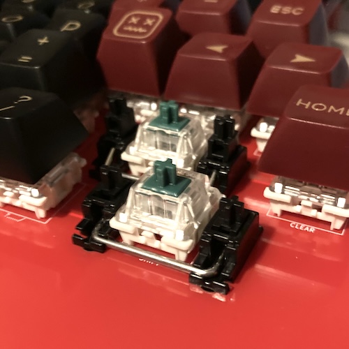
I then was able to stick on all the stabilized keys. Unfortunately, I found out that all of my left-Shift keys with stabilizer holes ended up rubbing on the left side of the case.
For that key, I ended up swapping out for a slightly narrower Shift key, that didn’t need to be stabilized, and removing its stabilizer mechanism. Still types fine, even though it does look really crooked in this picture. Hey, it’s version one!
And! All the other stabilized keys are doing great. Well, except for the space bar, which ended up fouling on the bottom of the case after all. I ended up filing just a little bit of the PCB holes down in order to let me move the PCB up, where the bottom of the space bar would no longer rub.
Hey. It’s… version one. Sigh.
One last complication occurred when putting the whole thing together. The plastic of the original keyboard is much thicker than a 1.6mm-thick PCB, so I ended up spacing the PCB using these rubber cable grommets. This way, the PCB doesn’t slide up and down in the case when it’s screwed together.
It’s not a perfect solution, but it works for now. I’m not sure if there’s enough pin depth on the Gateron key switches left to go to a 2.0mm or even thicker PCB.
Landing the Long Piece
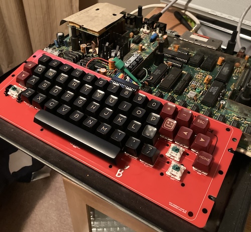
This hackjob keyboard is in good enough shape for me to load and play Tetris off FujiNet:
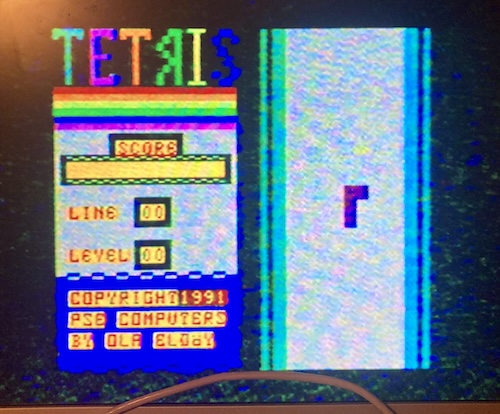
That’s enough for this project for now, I think. I wanted a keyboard that worked, and I have one. Sure, it’s ugly and funky, but so is the rest of the machine. It’s actually really fun to type with, which makes me more likely to use the CoCo.
Let’s review what lessons were learned from this adventure:
- 3-pin key switches are not the same thing as 5-pin key switches;
- Resistor networks aren’t added to boards for no good reason;
- No matter how much you measure, it’s never enough;
- Assembling stabilizers before putting them in the keyboard is much easier;
- Doing cool stuff with your old computer is always worth it.
Out of shame, I am not planning on releasing these early PCB files to anyone until it is a lot better of an experience. For now, it will just be “my thing.”
Another important part of this project is that nothing permanent was done that we can’t put back to stock, if I decide I wanted to do a hard membrane after all. The original keyboard is sitting in a storage bin with a bunch of other CoCo parts, ready to accept a new PCB whenever. Honestly, after this adventure, I realized that’s what I actually should have done – but I’ve had enough monotonous keyswitch soldering for at least a few more months, and now I have a working keyboard, which is a huge step ahead of where I was before I started.
Hey, doesn’t that Tomy Pyuuta also need a new keyboard membrane? Quiet, you.
-
You’ve no doubt noticed that
0turning into0is not the same pattern as with the rest of the bit-shifted number row. For whatever reason, most machines using the bit-shifted layout (PC-6001, CoCo, BBC Micro at least) simply don’t do anything with shift+0, which seems like a waste of a key. Following the pattern, shift+0 would become 0b00100000, or $20 , which is “space.” I guess I can understand why they didn’t bother, but it would be kind of handy to have a second space bar for when yours, say, rubs on the bottom of the computer’s case. Not like that’s ever happened to me. ↩