Assembling the PC-6001
Tags: computer nec pc6001 pc60 homemade-software
When you’ve got a computer as underpowered as 1981’s NEC PC-6001, you need to squeeze every ounce of performance you can out of it. BASIC just didn’t cut it. For many enthusiasts, the only game in town was machine language. It’s well past time for me to apply my Z80 assembly knowledge to the little white wedge.
Background
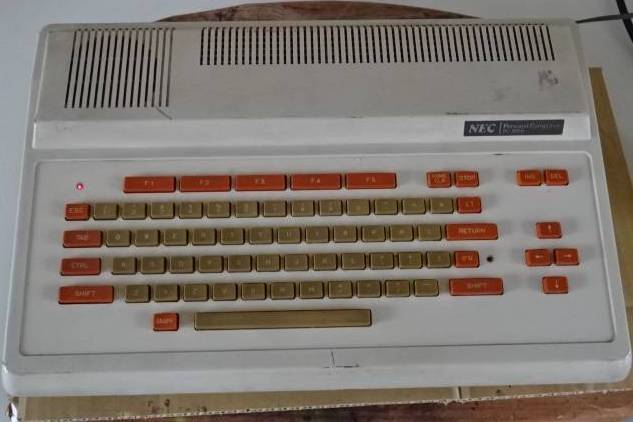
As regular readers have probably inferred by now, I really like the NEC PC-6001. It’s a low-spec Z80 system from the very early 80s. Programming games for it is a challenge, not least because of the small amount of RAM, but because of the mysterious Motorola 6847-like video chip inside.
Later generations of the PC-6001 changed out the 6847 for NEC’s own semi-compatible video chip, but whatever lessons I learn here will carry on to the more advanced machines. Lots of commercially-released games targeted the PC-6001mkII instead of the original-recipe model, so things can only get better from here.
Although I have workmanlike Z80 assembly skills, I have no idea how to program graphics for the PC-6001, so I decided that I would try and figure it out.
Environment configuration
As with previous Z80 experiments, my assembler of choice here is zasm. Zasm works well and has a reasonable (if occasionally cryptic) macro facility, which helps make boring chunks of code easier to write.
I reused a Makefile from a previous project, which essentially boils down to this handful of rules:
MAME = /opt/mame0253-arm64/mame
mame_dir = $(dir $(MAME))
local_path = $(dir $(abspath $(lastword $(MAKEFILE_LIST))))
mame_args = -skip_gameinfo -window
asm_args = -w
asm = zasm

pc6001.bin: pc6001.asm
        $(asm) $(asm_args) pc6001.asm -o pc6001.bin

all: pc6001.bin

clean:
        rm -f pc6001.bin pc6001.lst

run: pc6001.bin
        cd $(mame_dir) && $(MAME) pc6001 $(mame_args) -cart1 $(local_path)pc6001.bin

debug: pc6001.bin
        cd $(mame_dir) && $(MAME) pc6001 $(mame_args) -debug -cart1 $(local_path)pc6001.bin
I’m sure that anyone who uses make more than I do could make this shorter and snappier, but computers are fast. It’ll be fine.
For debugging, I use the MAME debugger. I suspect at least one of the PC-6001 emulators can import the LST file generated by the assembler in order to get symbols, but as far as I know, this is not possible in MAME. The most I’ve been able to do so far is add comments using a debugger startup script (-debugscript.) Thankfully, the programs I wrote in this article were so short that I could keep track of my symbols the hard way.
A great set of tips on how to use and extend the MAME debugger using Lua can be found on Matt Greer’s website; I wish that I had found these when I was first starting out.
Hello World
I was lucky enough to find a complete PC-6001 “Hello World” example at mm’s website. Not only does it explain how to make a viable cartridge image and print text to the screen, but it also gives the magic addresses for a couple other system calls such as locate and putchar.
My modified program is as follows:
; cartridge hello world demo
; from http://p6ers.net/mm/pc-6001/dev/4keprom/index.html

putchar: .equ $1075
cls:     .equ $1dfb
locate:  .equ $116d
putstr:  .equ $30cf

; cartridges start at $4000
.org $4000
; PC-6001 original cartridges are identified by this magic string...
.db "AB"
; ...followed by the address to jump to
.dw main

main:
    call cls
    ld hl, $0a08
    ; set position of the text we're about to print (roughly centred)
    ; H = column, L = row, both 1-indexed
    ; $0101 - top left, $0201 - first row, one column to the right?
    call locate
    ; print hello world to the screen
    ld hl, msg_hello
    call putstr

loop:
    jr loop

msg_hello:
    .db "Hello PC-6001!", $00 ; 14 characters long
Does it work?
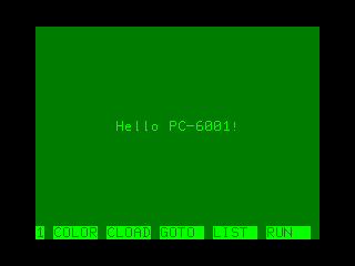
Nice.
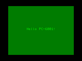
I fought for awhile longer and then found out that you can set the CONSOLE3 global ($fda6 ) and then call the internal CNSMAIN implementation of the BASIC command CONSOLE (at $1d52 ), and it will hide the function-key bar for you too. Sweet.
Simple Graphics
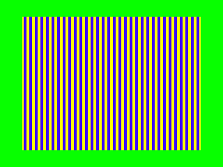
To figure out how graphics worked, I took a look at the P6 Tech page on the subject. On the PC-6001, you tell it where in RAM to pull the video buffer from by setting the value of a magic write-only I/O port, $b0 . Then in your newly-dibs’d VRAM, you write a bunch of “attribute” bytes that each control 16 lines of video – palette and resolution. The first 512 bytes of VRAM are dedicated to these attributes (keener readers than me will realize this number lines up with the 32x16 text mode exactly.)
It took me a bit of spinning in circles to understand exactly what was going on here, as the naturally funky level of free-association poetry that Google Translate sometimes produces from Japanese technical documentation was on full display here. Ultimately, it took some of Inufuto’s code (thank you!) and a bit of pen-and-paper math to figure out how the layout works.
In the mode I’m using, mode 31, you have 128 x 192 pixels to play with and 2-bit colour (chosen from one of two palettes – I use green, yellow, blue, red.) That means that each line is 128 / 4 = 32 bytes long, with each byte containing the values for four pixels.
For instance, here is the pattern 0b01101001, or blue-yellow-yellow-blue, applied to every line of the video, all 6144 bytes of the buffer:
The program isn’t too complex, although I’m sure it could have been done shorter. I really need to figure out how to write a 16-bit loop macro in zasm:
    ; now try to get into graphics mode
    ld a, (port_b0)
    and $f9 ; clear the vram address bits 1, 2 -
    ; that tells the 6847 VRAM starts at $c000
    out ($b0), a

    ; write attribute bytes
    ld hl, $c000
    ld bc, 512 ; 512 attribute bytes (for 512 characters in text mode)
set_attributes:
    ld (hl), $8c ; green yellow blue red (mode 3)
    inc hl
    dec bc
    ld a, c
    or b
    jr nz, set_attributes

    ; wipe the display portion of VRAM, which starts
    ; after the attributes ($c000 + $200 = $c200)
    ld hl, $c200
    ld bc, VRAM_ROW_SIZE * VRAM_HEIGHT ; or 128 x 192 divided by 4 = 6144
erase_vram:
    ld (hl), 0b01101001 ; blue yellow yellow blue
    inc hl
    dec bc
    ld a, c
    or b
    jr nz, erase_vram
Pretty cool stuff. Now I had to figure out how to draw something actually useful. I had some Python code lying around from earlier when messing with dithering, so I wanted to find an image that had a lot of blues, yellows, greens and red and see if I could get it to look good on the PC-6001.
Monet’s Meules is as good a choice as any. It’s got all four colours!

Someone paid $110 million for this painting, but we can draw it on the PC-6001 with just a little bit of effort and some very nasty dithering code…
# PC-6001 mode 3 is pretty brutal: green, yellow, blue, red
MODE_3_PALETTE = [
        0, 255, 0,
        255, 255, 0,
        0, 0, 255,
        255, 0, 0
        ]

from PIL import Image, ImagePalette

palette = Image.new('P', (4,1))
palette.putpalette(MODE_3_PALETTE)

oldimage = Image.open('meules.png').convert('RGB')
newimage = oldimage.quantize(4, palette=palette)
newimage.save('meules-4.png')
This Python script produces the following quantized image. PIL used the default dithering routine (Floyd-Steinberg.) I’m sure there are better choices for this kind of extremely-low-colour palette2, but it looks surprisingly good anyway… despite having obliterated the trees.
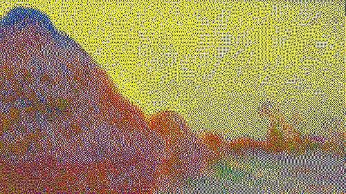
After adjusting the dithering script so that it also resizes the image to the appropriate width for the PC-6001, we end up with a lot of pixel data ready to be blasted to the screen.
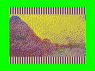
Because of this mode of the 6847’s unique portrait aspect ratio of 128x192, I first thought it would be a clever idea to rotate the image 90 degrees before display. This way, it can fill the entire field without wasting any pixels. You just have to tilt your head… or use tate mode.
I wrote some more quick Python code to convert the whole mess into a packed .db array for the assembler. After one embarrassing screw-up where I realized that I had accidentally given it too long of a length value, overflowing the PC-6001’s memory (and somehow reading part of MAME’s internal state into the PC-6001’s video RAM in the process) I was able to get some nice looking Meules:
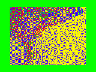
Okay, that’s pretty wild. It’s amazing how even sloppy dithering fools our primitive monkey eyes.
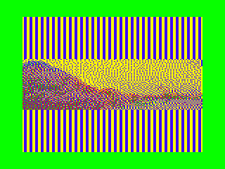
I also tried a horizontal version, but the width wasted a lot of space. You can see the remains of the blue/yellow test pattern behind this image, which is a mere 72 pixels tall out of 192 pixels of room…
I tried scaling it disproportionately and I think it just doesn’t… look like the original picture. It’s like when your weird uncle shows off his collection of full-screen DVDs.
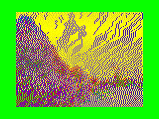
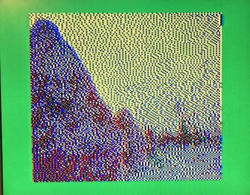
As a quick hack, I decided to double up the rows, drawing each pixel twice vertically. I thought it looked pretty okay, but the stretching in the grain is very noticeable.
“Full-screen” it is. You’re welcome, Unc. Let’s take a look at it on real hardware.
Hardware configuration
To test on real hardware, I decided it would be best to use my own cartridge. Even though I have a PC-6006 with ROM sockets, ROMs in a compatible pinout (µPD2716, µPD2732, µPD2364) are not easy to come by. These earlier ROMs don’t follow the same JEDEC-pinout as the 27c64, 27c128, 27c256, 27c512 etc that I’m used to using (and have on hand.)
Although I can use an adapter, the PC-6006 cartridge only supports addressing 8K of each ROM inserted as well. That’s not a particular obstacle here, as the Monet-infused ROM is under 6K even without compression, but the combination of these two issues bug me enough that I wanted to use my own cartridge.
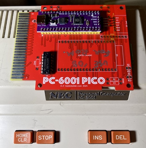
Because the program doesn’t need expanded RAM, I was able to grab my bodged-up Pico cartridge from the previous entry and throw it right on there. How convenient!
Actually, it’s not convenient at all. Putting a new ROM on the Pico cartridge consists of:
- Assembling the ROM;
- Padding the ROM out to 8K or 16K;
- Dumping the ROM out to C array format and putting it in the header;
- Recompiling and re-flashing the Pico firmware.
Still, “popping it in” takes less than 10 minutes, which is faster than waiting for a UV eraser to erase a ROM so I can burn it again. Don’t ask how long it takes if I misplace my USB-C cable.
We’ll have to figure out a quicker method for this develop/assemble/flash/test cycle in the future – even figuring out how to keep the A8PicoCart’s drag-and-drop flash functionality would be a step up from this. Still, it’s good enough for now.
My somewhat-untrusty Samsung 910MP LCD was on the bench, so I opted to use it for this test. And it looked okay!
But: I know what people really want here is weird CRTs. Here’s the same demo on a dinged-and-scratched Magnavox RD0510 I found at a flea market. It’s a 5” portable colour CRT with a composite input.
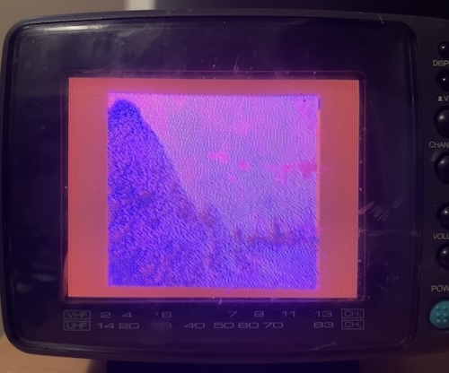
Oh no! Those haystacks look much less appealing on this set. I have noticed that the 6847’s method of generating composite colour makes some television sets really mad, although all the detail is clear. This set works fine with other systems, although it does have a troubling pink hue for a little while until it warms up. Likely a future project. Oh well, it’s still neat to have it on a tiny little CRT.
GitHub repository
Because this project was built on the hard work of so many others, it would be silly not to distribute my own code as well. If you’re interested in how this was programmed, come check out the GitHub repository for pc6001-assembly-programming. Be forewarned, it’s pretty rough in there, and has a lot of other code from previous PC-6001 projects intermingled with the files you want to look at.
The Future of Touching Bits
Now that I have done the absolute bare minimum to figure out how to program the PC-6001’s graphics system, I’m ready to move onto something more exciting. Making a small, original arcade-like game for my favourite little computer has been on my “dream project” list for quite some time, so maybe I should sit down and do it.
A port of the Sharp MZ game Numbertron could also be really fun, and wouldn’t need anything more than the PC-6001’s tile modes. It would be a good excuse to see if the PC-6001 port of the z88dk tools are up to snuff enough to program the system in C.
Obviously, displaying a static image is a lot different from anything with motion in it, so learning all the performance tricks will be essential for a smooth arcade game without flicker. There appear to be lots of cool strategies for quickly displaying sprites in order to overcome the PC-6001 graphics system’s glacial speed. For instance, the newly developed PC-6001 game XeGrader appears to use self-modifying code. That’s a technique I haven’t used much, but could be a mind-bending amount of fun.
Where would you like to see this mess of Z80 assembly go next?
-
In the TRS-80 CoCo, I think that this would be referred to as the “CG6” mode, as that’s what Motorola called it. ↩
-
PC-98 games often appear to have used an ordered-dither technique, such as Bayer dithering, in order to stretch the limited palette for jaw-dropping effects. That would probably work well here as well. ↩