Three Times the Fun
Tags: computer apple apple-iii corrosion repair
If you think “funnest” isn’t a word, you’re wrong. Maybe you just haven’t met the Apple III yet, Apple Computer’s comprehensively-failed attempt at turning the hobbyist miracle of the Apple II into a serious business computer. If anyone asks, I’m a serious business person, so I’m allowed to have this.
What is the Apple III?
The Apple III was Apple’s attempt to get into the business-computer market. By taking an Apple II+, expanding it, and chucking a bunch of cool new features on it, the idea was that they could produce a system that was more turn-key than hackery. Tandy followed a similar idea with their TRS-80 Model II.
There’s a lot of cool stuff added to the Apple III, like a standard 80-column mode, paged memory management with at least 128kB of RAM out of the box, RGB(!), and a built-in floppy drive and disk controller. It’s also got a new operating system, Apple SOS, with a hardware abstraction layer and a filesystem with sub-directories.
Unfortunately, the dreaded second-system effect was on full display here. In addition to the useful features outlined above, Apple also added a bunch of odd gimmicks and confusing evolutionary dead-ends. Plus, even after a troubled and lengthy development cycle, the original released units were incredibly unreliable.
After awhile of trying to ship working units, Apple made a revised model – the Apple III+ – and greatly incentivized unhappy customers to upgrade to the new model.
Let’s be honest, though. “Weird gimmicks” and an unloved computer is basically catnip to me. One of those gimmicks is the cast aluminum case. Made like a car engine block, the main body of the computer is one giant chunk of metal. While very impressive to look at – maybe my favourite aspect of the machine – it doesn’t do the thing any favours, thermal-wise. You’ve probably heard the story about Apple support telling folks to pick up and drop their Apple IIIs on the desk; I bet you can figure out before the end of this article what part of the machine that fixes.
What’s wrong with this one?
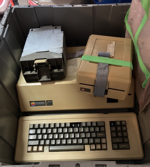
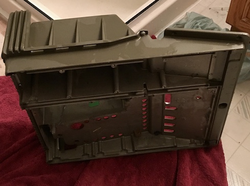
Reportedly, mouse pee. This marks the third Apple III I’ve heard of that has been peed inside by mice. It could be because the cast-aluminum unibody doesn’t have any block-off plates for unpopulated card bays, so mice can easily get inside the massive openings in the back and pee inside it.
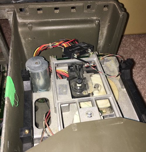
The first thing I did was pop off the top plastic case, which is accomplished by turning the two quarter-turn fasteners, one on each side, and removing the plastic. This exposes the top of the card cage, a speaker, and not very much else.
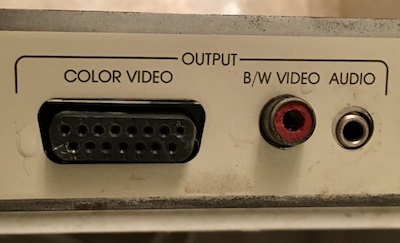
Yes, the Apple III can do digital RGB. However, this is not a “planar,” for lack of a better term, RGB output. Like the AppleColor 100, the output is actually indexed. I haven’t done anything with this yet; for now we’ll be using the “black-and-white” composite video jack to test the computer.
Check out that headphone jack. Yeah, no beeper speaker for us. This baby has an actual DAC.
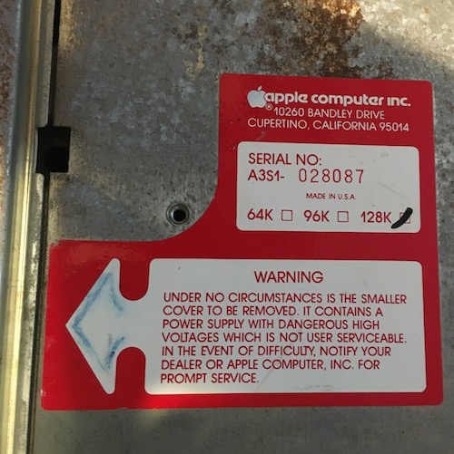
I’m lucky to have a 128K model here – it’s an early board and therefore the most troublesome. Huh. Maybe I don’t know what the word “lucky” means after all.
The 32K and 96K configurations would probably have been produced from not filling up the internal memory board quite as much. But I’m getting ahead of myself.
It’s also worth noticing the address here: Bandley Drive! Apple amalgamated their various buildings and moved to 1 Infinite Loop in 1993.
Last: “In the event of difficulty?” Don’t worry Apple, I don’t plan on having any difficulties with the power supply.
On to the keyboard! This machine has clearly gotten smacked around, and a bunch of parts on the keyboard are broken as a result.
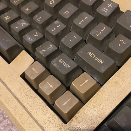
I’m not a fan of the layout of this arrow key cluster at all. I would have preferred an hjkl-style layout at the very least. Apple agreed, which is why the III+ comes with that ever-so-slightly better layout from the IIe.
One interesting thing about these arrow keys is that they are actually two switches in one. By pressing down hard, you’ll feel a second momentary switch engage. This appears to be the equivalent of the “repeat” key on the Apple II+ keyboard, so you can scroll without having to repeatedly press arrow keys.
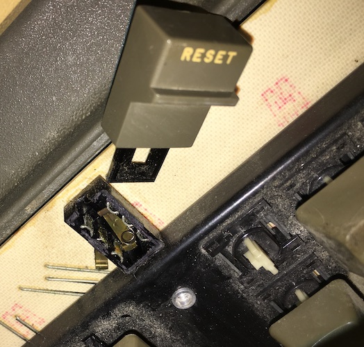
I had no idea where to start rebuilding this reset switch, so I put all the parts I could find in a Ziploc bag and left it for another day. It’s not like the reset key is important for Apple II programs or anything, right?
Getting screws out of the underbody of this system is difficult. Galvanic corrosion – interaction between the aluminum of the case and the mild steel of the screws – has been made worse from the rodent damage.
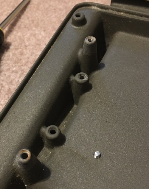
Frankly, it’s also kind of dumb that you have to flip the entire computer over to get the motherboard out. I know it’s the same deal with the Apple II series of computers, but it’s so much more annoying with the heavier cast aluminum case.
The internal Disk III floppy drive is going to need some work. For starters, it’s belt-drive, and one of the mounting posts for the PCB has cracked. It’s also absolutely filthy. I put it to the side for now and kept going with the rest of the computer.
There’s a cool Apple logo moulded into the underside of the unibody. Very stylish.
![]()
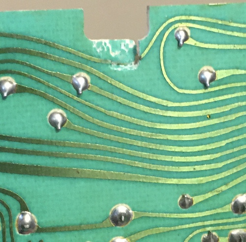
In the process of being dropped on the keyboard, the main keyboard circuit board (there’s two of them, with one belonging to the arrow keys) has cracked, severing a trace.
Keystems
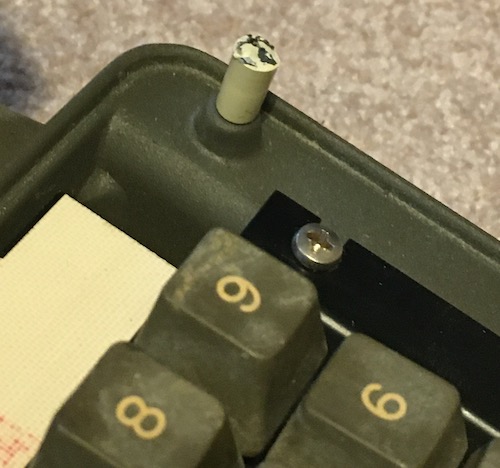
I felt sad looking at the badly-beaten keyboard and all of its punched-out teeth, so I decided to get some new key stems for it. I checked online, and vendors such as Joe’s Computer Museum were selling Alps long- and short-stems. I wasn’t sure which kind I needed, so I pulled a cap of an intact key.
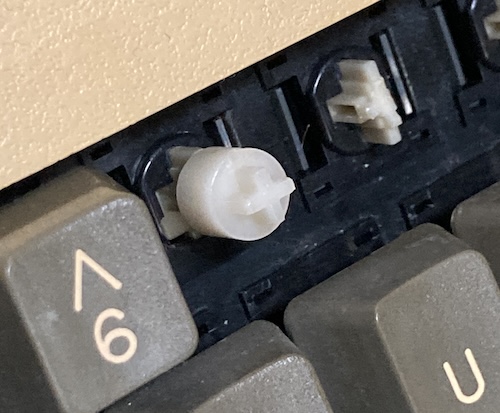
This weird cylinder-shaped thing on top of the keystem is not what I expected at all. It seems like the other keys sheared off here, where the base of the cylinder makes a right angle with the stem.
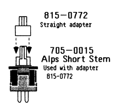
After checking with the Apple III Technical Procedures, Appendix A, I was able to determine that this was an 705-0015 “Alps Short-Stem” key switch with a 815-0772 “Straight adapter” installed on it.
So I need to get some replacement short stems, and a straight adapter. I don’t have a good source on getting a replacement “straight adapter” for now, but I plan to measure this and make something that can be 3D printed. There’s no sense in spending money and time on repairing the keyboard if the mice have completely destroyed this poor computer.
Scrub A Dub
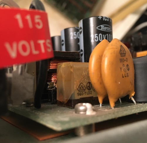
I removed the power supply and checked it out. It looks okay, except for a cracked “RIFA” brand X2 capacitor. This would probably have turned into magic smoke if I had been dumb enough to power the supply right now. I put this on the to-do list and kept going.
While I was at it, I started cleaning the disgusting case.
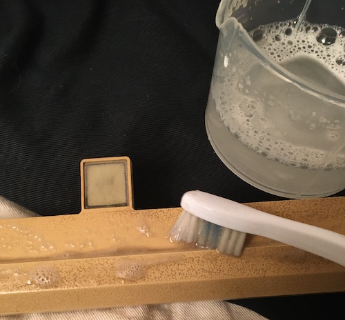
To clean the textured case plastic, I used an old standby. I chucked a bunch of Oxy-Clean into warm water and then used a toothbrush to scrub. Lots of dirt came out, and the water in the cup got filthier and filthier every time I stuck my toothbrush back into it, even with regular rinses in the sink.
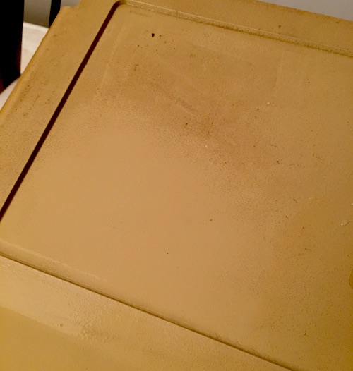
Soon, the plastic keyboard frame and the top case shroud were looking much better, and the cup was pitch black.
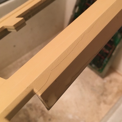
Unfortunately, once cleaned, I realized that the keyboard frame had two cracks in it, around the reset button. The crack doesn’t go the whole way through, but if the frame is flexed it does get wider. I decided to leave this alone for now and try to figure out how to stiffen the backside later.
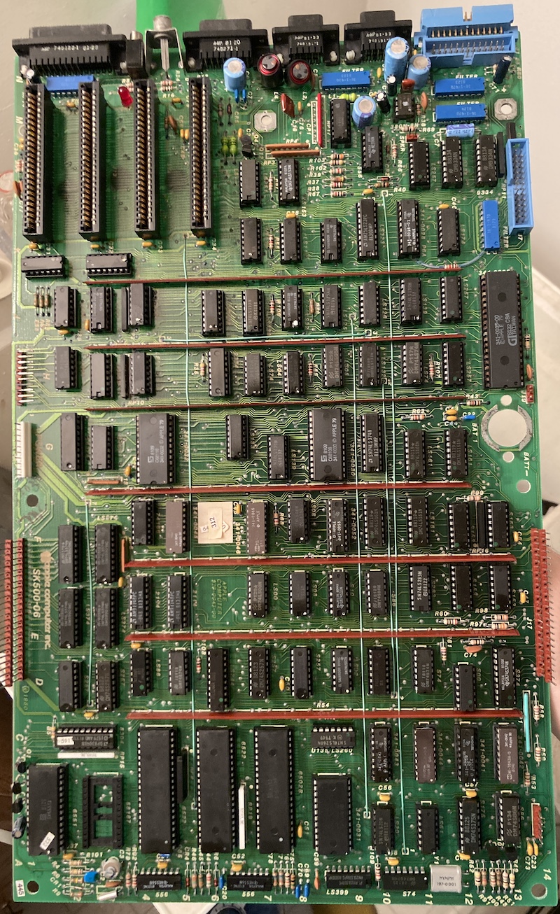
Logic Earth, Logic Board
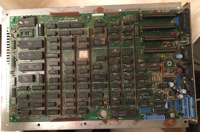
Removing the motherboard is straightforward if awkward. All you have to do is flip the computer over and then unscrew the plate holding the motherboard from the underside, then pull it out. It probably helps that the previous owner had already unplugged the power supply, disk drive cables, and all the cards first.
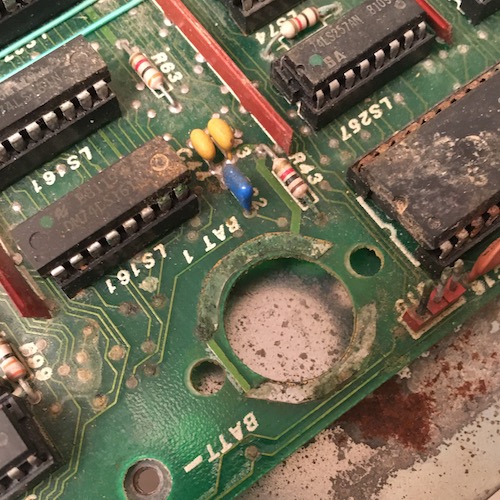
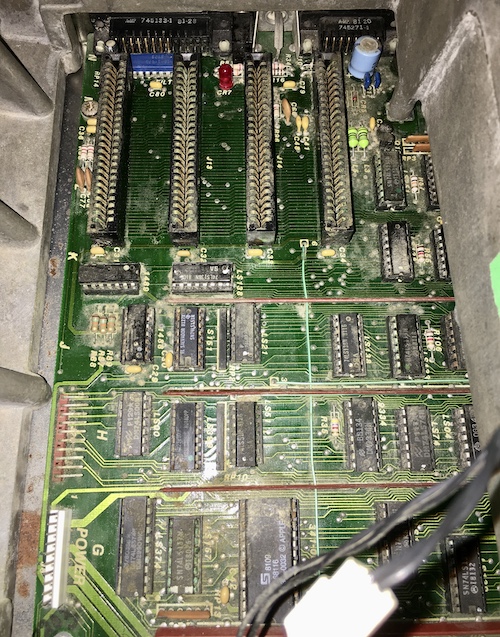
Since this is an early board, it has an onboard clock battery. I’m not sure what kind of clock battery, as it has thankfully been removed, but the evidence of its presence (and leakage) is obvious. Not the biggest of our problems right now, but I needed to deal with it eventually.
At the other end of the board, a missing “58167” part initially gave me some worry, but a quick search showed that the MN58167B is a clock/calendar IC, which is considered optional nowadays. No battery, no calendar, no worries.
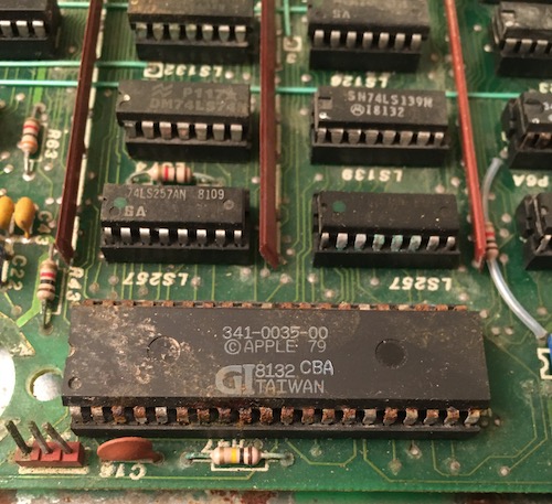
The keyboard controller IC nearby is pretty raunchy, with rusty legs and a corroded socket. It’s responsible for decoding the keyboard matrix into ASCII codes for the computer. At least it sounds like this might not be a custom part, and there is an excellent community-made aftermarket replacement, built around a PIC 16F18875.
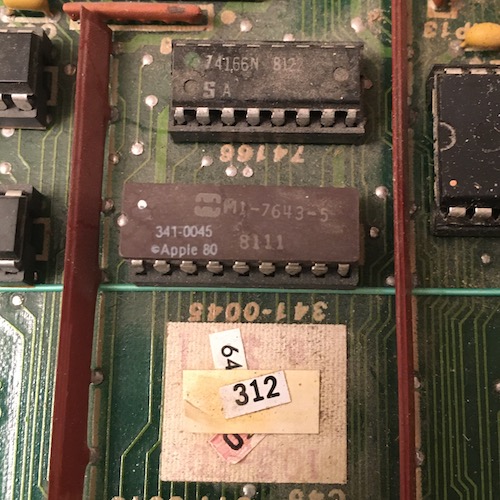
I saw a lot of these weird little 18-pin DIP Apple-branded chips. A quick trip to the Apple ASICs site reveals that the 341-0045 is a ROM (specifically, a PROM) that’s responsible for “bus/memory select logic.” It takes ten inputs and produces four enables. There’s dumps of these weird little ROMs out there, so if one of these are bad (or if I want to upgrade to a 5V memory board) I can hopefully make a new one.
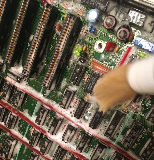
I used a boar hair brush and warm water with dish soap to clean off all the large gunk. It might not be the most clinical approach, but I assure you that this board was gross enough that this was the only way I was going to be able to touch it with bare hands.
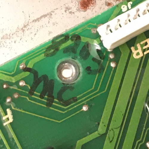
Somehow, despite all the horrible pain this board has been through in its life, this sharpied assembly mark persists from 1982.
Sonication Rules The Nation
I did the logical thing at this point and bought more tools. Namely, a 30L Vevor ultrasonic cleaner. This thing is massive, and it takes an absolute boatload of distilled water every time I fill it up. At first I was going to build a little mini-workbench and install an outlet in a storage room to run it, but I couldn’t take the waiting anymore and just plugged it into the wall in my laundry room.
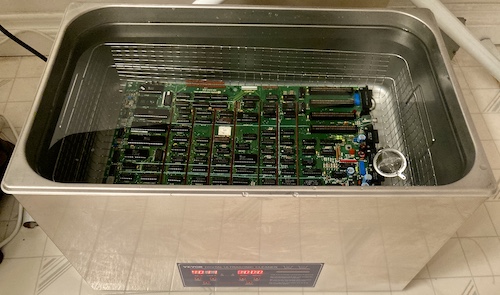
What better board to take it on its maiden run than this awful Apple III logic board? I set it in for eight minutes, and when it was done, the board looked cleaner – but not by much.
I asked around and Mark from the Mark Fixes Stuff YouTube channel set me straight. The solvent needs a much higher temperature (over 54°C) which means I needed to pre-heat the water and solution. For several hours, with the lid on.
After a couple hours, I finally had the temperature high enough. I measured the solvent and poured it in, then ran the ultrasonic empty for ten minutes to “de-gas” and mix the solution. After that, the Apple III board went back in the steaming soup, and was run for another eight minutes…
That did it! Just so I wasn’t wasting all the energy required to get the solution up to temperature, I then threw in every dirty board I could get my hands on and ran them too, along with the rest of the Apple III’s boards. Everything turned out much better, even battery-soaked carnage. I drained and disposed of the ultrasonic’s contents immediately after, out of fear of corrosive goop still lying around in the water. It was here that I remembered just how heavy nearly thirty litres of water really is, and how hard it is to drain it out of the tank without making a huge mess on the floor. Putting this thing up on a workbench would have made things a lot easier, and that’s since been corrected.
RIFA Madness
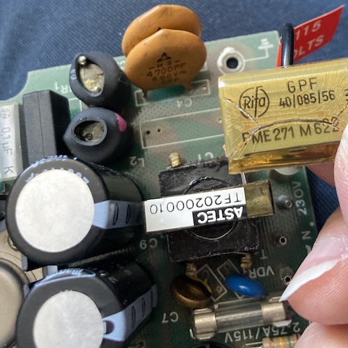
I decided to remove the cracked RIFA-brand safety caps from the power supply, but while I was in there I tried out my then-new Peak ESR70 ESR meter. That meter is a little picky, and immediately discarded every cap from the power supply that I put in front of it as “bad.”
The funky 70s power switch felt very weird, but it might just be the way the switch is designed, as it seemed okay on a continuity and resistance test. I’m thankful that it isn’t arcing, because I would have had to try pretty hard to find a replacement for it.
Luckily, the power supply uses all common values of caps, and so I was able to swap all of the rejects. One cap was glued in, and I’m not entirely sure why. Maybe because it’s close to the primary side and more likely to be vibrated?
I was confused by a resistor that had been clipped out. However, it looked like the same one is clipped out on other photos of Apple III power supplies.
A lot of the 1000µF caps are super tall ones in little clip-in plastic mounting brackets, which I had initially assumed were meant to prevent vibration without having to glue the cap in. You see these brackets in car ECUs.
They happily snapped onto the replacement caps, and actually seemed to hold them in place fairly well when I flipped the board over to solder it. Maybe that’s what they’re for!
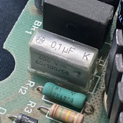
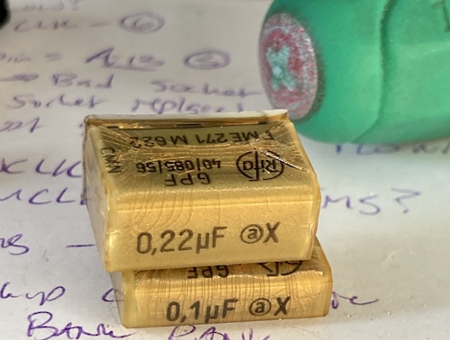
I was surprised to see this new RIFA-branded cap was grey, having only seen yellow ones in old junk throughout the years. Yes, I put in new RIFA-brand caps. I assume they’ve figured out how to make more reliable safety caps in the last 40-ish years, and if not, I’ll deal with it in the 2060s.
Fixin’ Time
Now that the main logic board was clean enough that I could touch it without gloves on, it was possible to give it a closer inspection and see if it was safe to introduce power. I popped a couple of the larger chips out and re-socketed them, and was pleasantly surprised to find that the sockets were not nearly as crunchy as I had expected.
The next thing to do was to reinstall the RAM board. It sits atop the logic board. There are two kinds of RAM boards released with the Apple III: the early 12-volt board, and the later 5-volt board. This, in case you couldn’t guess by the very cool stacked DRAM ICs, is an earlier 12-volt.
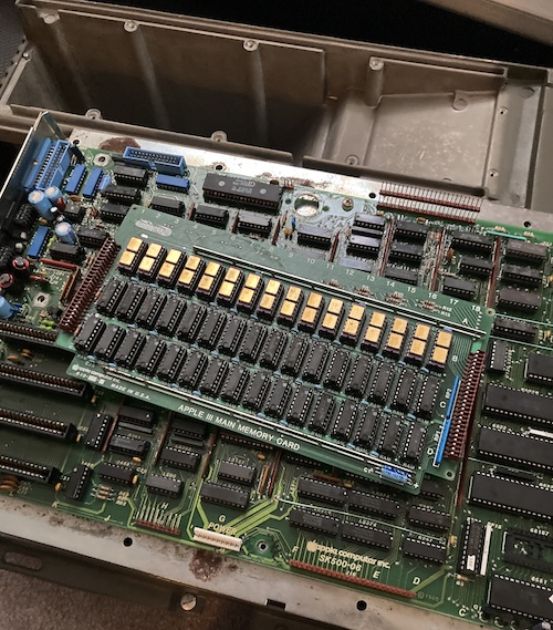
Because the memory board had been shipped loose in the box, I didn’t know which way it went on. The stacking connectors which hold the memory board above the motherboard are not keyed – usually I’d expect to see these things at least staggered. Sloppy.
After looking at some Googled pictures of other people’s Apple III motherboards, I figured out that the “notch” goes towards the card slots at the back of the computer. It feels very flimsy to work with these connectors, and I bet this awkward high-rise, high-speed connection represented a big part of the thermal failures on these machines. This was almost certainly what was being reseated during that Apple support tale of “lift the computer off your desk and drop it.”
I had to do a few assemble-and-disassemble cycles before I could keep the power cord from being pinched by the case, but ultimately I triumphed and had an ugly but clean motherboard and partially-rebuilt power supply in the ugly but somewhat less clean case.
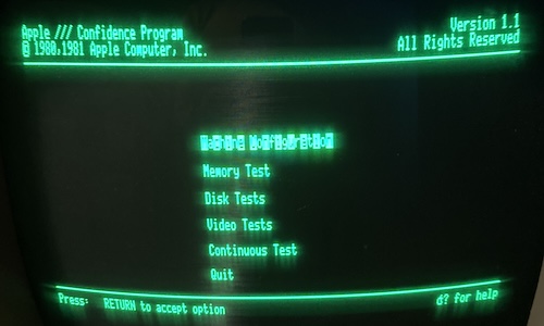
I decided that I would start the system with as little attached as possible: no keyboard, no disk drive, no cards. This would make sure that if one of those were funky, I wouldn’t be blaming the computer itself. Nothing left but to fire it up. I used a Monitor III that a good friend found at an estate sale.
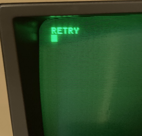
“RETRY.” Okay, wow, that’s a good sign. Blinking cursor, legible text, text that makes sense as human communication, stable raster… a lot of things had to go right to get to this point. I was feeling pretty good.
After a quick poll of anyone I could find with Apple III knowledge, it turns out that this message means the computer is waiting for a disk. Of course, I didn’t have any disks, and the disk drive wasn’t hooked up (or even assembled) anyway.
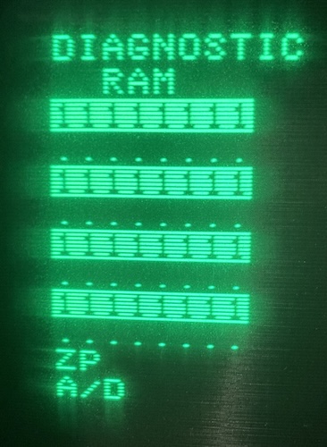
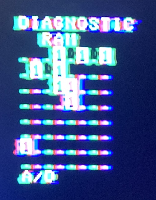
Let’s try a cold restart. I flipped the power switch off and then back on again. This time, instead of “READY,” I got this “DIAGNOSTIC RAM.”
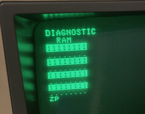
It should all be ., but instead half of the rows are 1. Exactly half. That’s suspicious. I was stumped on this one, and couldn’t find anything obvious in either Apple documentation or forum lore, and couldn’t figure out what would control only odd bits on the memory schematic. At this point, I also needed to clear the workspace I was using for the Apple III, so it went back into the tote for a few months.
I had a bad feeling about the “READY,” too. I had been told that not having the keyboard connected (or having a bad power-light bulb in the keyboard) would keep the computer from progressing past the keyboard diagnostic1. And yet here we are, well past the keyboard diagnostic with no keyboard plugged into the computer. That’s suspicious, especially because of all that corrosion damage to the keyboard controller we saw earlier, and the crack in the keyboard PCB.
A more intensive test is called for.
Test Software
For testing, I wanted to make at least a disk of the Apple III “Confidence Program.” This tool has a bunch of options for testing hardware: thorough memory tests, machine feature profiling, disk drive testing, tests for all the graphics modes, and a soak test.
MAME had the disk image in its Software List, so I grabbed a MAME dump on the Internet Archive and used the ia utility to download all the images that matched *apple3*. I ended up with some images like Business Basic, the Apple II emulator disk, and Apple Pascal, as well.
I was about to hook up the Apple IIe and do a disk-writing session with ADTPro, but then I came across this project by “Thorsten B” which is meant to adapt the 26-pin Apple III to use the 20-pin Floppy Emu. I immediately sent away for the board and made up a quickie ribbon cable to test it.
This is better in the short run: I was already working on a suspect computer, so I didn’t also want to include suspect disk drives (especially ones still full of gunk) and floppy disks into the diagnosis tree. I know that the Floppy Emu works reliably, and that the adapter has been tested to work, so the number of potential new problems that could be created were minimal. I hoped.
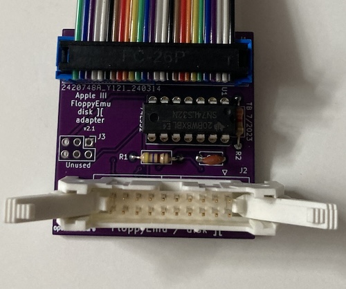
It was a little hard to find a 20-pin shrouded box header with a central locking tab, so I ended up using this giant one with latching claws. This means it looks a little dumb, and the nice case they designed for the PCB doesn’t even come close to fitting, but it works. I actually really like these latching claws since it makes it easy to remove the cable without pulling on the ribbon and potentially damaging the crimp.
Unfortunately, when I started up the Apple III, it seemed to make no effort to boot off the Floppy Emu (which at least was getting power.)
A Firmer Emu
After a few months of wondering what was going on, it turns out that the Apple III’s super tiny 4K boot ROM only supports booting off an internal floppy drive2, so I had already made one obvious mistake.
I took the computer back apart again, because the connectors are not readily accessible with the motherboard installed. As beautiful as this case is, I was definitely getting tired of dealing with it. I decided I would put the power supply and motherboard on the bench “loose,” and just deal with the extra space they took up in the dismantled configuration for a little while longer.
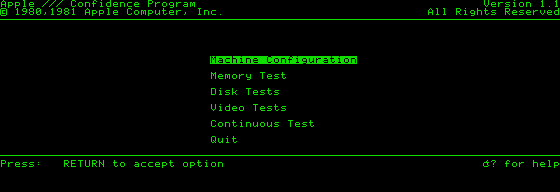
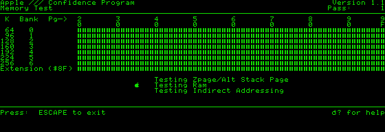
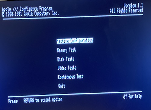
The Floppy Emu came to life and actually seeked tracks. This beaten-up Apple III is alive enough to try and load software off disk! The Confidence Test program quickly loaded, although you can tell something is not right.
Something is clearly going on with every second character; only odd characters are highlighted on the menu. Hmm! Just like the zero page diagnostic RAM failure. However, the keyboard works to navigate the menu, and although there’s some graphical corruption left behind when the “help” menu is brought up, I can run it like this for quite some time before anything goes wrong.
However, when I selected a menu option, the system would read several tracks from the disk and then go to a black or partially blank screen, unable to start any of the sub-modes.
Restarting the machine kicks us back to the “Diagnostic RAM” screen, now with a complaint about “A/D,” but with the keyboard attached, I learned that I can hold down CONTROL to guarantee that it will attempt a disk boot every time.
What’s A/D?
At this point, I was pretty convinced that at least one of the DRAMs on the RAM card had gone to silicon heaven. However, I couldn’t find my 1-bit or 4-bit DRAM tester boards, so I decided to do a little bit of research before wasting an afternoon digging through the pile of crap on my desk.
Reading the poorly-OCR’d service manual much more closely than I had previously, I was able to figure out some more about how the diagnostic screen worked and what its cryptic errors were.
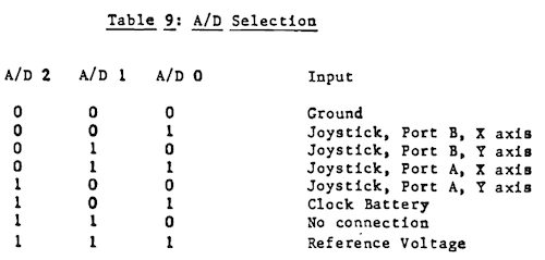
A/D is an indicator of a bad read of either the high or low reference voltage of the 9708 chip located at M9.
That’s something to take a look at later, but for now let’s try to get things to boot and run well enough that “non-working joystick” becomes something I can worry about.
Remembering what you’ve lost
A little further down, we also have some suspects to check for “ZP” failure:
ZP indicates a zero page register failure. The zero page register is port B of the 6522 located at B6. Other possible chips for this failure are the S257s at locations D7 and D8 or the Ls132 at D4. This is where the zero page portion of the address gets fed to the system memory. Also note the NOT ZPGE signal which should originate at the LS51 at B11.
It also explains where each “bad” signal goes to on the memory board:
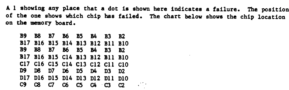
Notice that the same chips appear multiple times, interleaved. This would be useful, except for the pattern we’re seeing; it is unlikely to my eyes that exactly half of the chips have gone out for a smoke and never come back. One of the TMS4116 chips, at position C-17, looked visibly dodgy, with some kind of still-caked-on environmental contamination having potentially crept inside the package. Could it be screwing up multiple lines? I didn’t think so, especially not without getting super hot in the process.
A more likely suspect for a failure this big is the super sketchy connection between the RAM board and the Apple III motherboard, so I decided that I would do a crude continuity check and see how things looked from there. That passed with flying colours – all 50 pins seemed to be making continuity, which is honestly more than I expected.
To be thorough, I pulled the RAM at C17 out and put it in the 4116 RAM tester I had on hand. It failed nearly immediately and consistently, with four angry red lights showing what I assume is a basic write/read failure. Two others in the “C” row had intermittent failures, and either showed up as 8K or failing timing/decay tests, but I suspected those were corroded legs. All the others in the “C” row tested out just fine.
So this was still worthwhile (it found a bad chip!) but, again, because of the pattern of failure I suspect our problem is somewhere in the addressing logic.
Because the 74LS51 at position B11 was very easily accessible, I pulled it out and popped it into my TL866. minipro claimed that the chip failed:
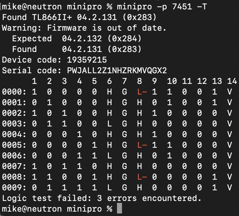
However, a known-good 74LS51 also tested identically. The test case as described by Minipro makes sense to me with the datasheet, but something else is going wrong with that test.
Thanks for the memories
Grudgingly, I ordered some AliExpress TMS4116s to replace the three bad ones I had found on the memory board. Once those were swapped in, the self-test at startup displayed something very different:
It looped between this bad-memory screen and a screen full of rainbow vomit:
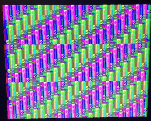
“ZP” is gone – with a functioning zero page, I can now run a whole lot more software. Plus, the Confidence Program menu is not checkerboard-y anymore. Despite the death loop, it continued to boot to disk by holding control and open-Apple.
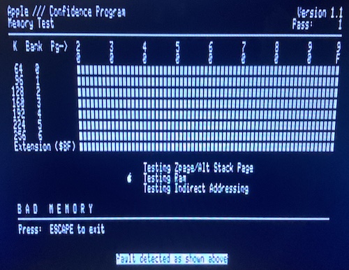
However, the RAM test fails instantly, claiming “BAD MEMORY.” Yeah, I know the memory is bad, that’s why I’m running the RAM test.
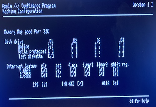
The “machine configuration” test tells me that the Confidence Program believes itself to be running on a 32K Apple III, which is not a configuration that exists, and also (for you math majors out there) is a number significantly smaller than the 128K this thing is supposed to have. So we still have bad memory somewhere.
Now that the zero page was working, I suspected the RAM diagnostic error message had become more accurate. I went back to the service manual “map” of which ICs to replace, and started spot testing them.
Almost all of the failing chips were “B” row Mostek MK4332s, which I had not figured out what to do with just yet. It’s a special module, as shown on the preceding link, and I don’t have replacements to hand, so something would have to be fabricated.
However, D17 was a regular 4116, so I tested that. It failed immediately, so I replaced it, and suddenly that bad bit was gone from the RAM test. The Machine Configuration window of the Confidence Program now said I had a 64K Apple III. The RAM test still would not proceed past “BAD MEMORY,” but at least there was some improvement.
As for the MK4332s, I don’t want to condemn these beautiful gold parts to the scrapyard without first testing them. Unfortunately, the DRAM tester that I’d used thus far does not directly support the 4332’s pinout. For a first test, I swapped the 4332s at positions D2 (bad) and D3 (good,) and the error followed the moved chip.
Test some MK4332s
I quickly dashed off a weird little bodge board to convert the 4332 to a 4116 pinout, so I could test the 4332 in my 4116 tester. Glad I got that out of my system.
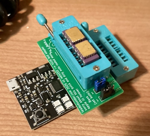
Since the 4332 is basically “two 4116s3,” the way this works is that there is a switch to toggle between which bank is being tested. You must test each 4332 IC twice, one for each 4116 inside.
Yes, I did think about writing a whole microcontroller-driven test, but the existing 4116 testers already have fancy timing tests and short protection that I don’t want to implement.
I wish I had dug through my used-parts bin more and come up with a pair of 3-pin slide switches instead of the jumpers. It’s kind of annoying to move them between runs, but I’m not doing this all day.
Another thing I wish I had done was add pull-up resistors to the CAS and RAS lines. Without them, I had a frustrating evening where I had tons of sporadic failures of chips the Apple III’s diagnostic test had been happily passing.
At first, I thought it might be the test being just that much more hardcore, but gradually I realized I had made a silly error. Like usual.
Not only that, but I had written a note to myself (in the draft of this very article) for when the board arrived to add those pull-ups, and had already added them to the PCB in KiCad. Thanks for nothing, Past Me.
Once I added those pull-ups to the board, I had what I expected. Seven chips failed, as the III had claimed, but an eighth also narrowly failed the RAM tester (2/4 lights lit.) I decided to get rid of that one, too, and make it an even eight to replace.
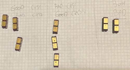
If you ever need this tester, let me know. I strongly doubt I’ll ever see another 4332 in my life, unless used Apple III prices get a lot more reasonable.
Hopefully, there is some kind of magical fix for these 4332s in the future, and they can go back to work one day. Looking at the corners of the individual “4116s” stacked on top of the board, I can see some dodgy-looking solder joints, but I’m not convinced that it’s safe to hand-flow them, and the joints in between the modules are impossible to reach with an iron.
Most of the failed modules are still at least half good, with only one of their onboard 4116s dead, but I don’t feel confident enough in the long-term reliability to hot-air off the dead stacked 4116 and swap it to make one good chip out of two bad ones.
Even with the damaged silkscreen, I still felt they were cool enough to hold onto, if only as modern industrial art.
Make some MK4332s?
I had a couple ideas about how to replace the MK4332s. For starters, a quick web search found a Joe’s Computer Museum page about how to make an MK4332 out of two 4164s, which is something I have quite a few of lying around. Thanks, Joe.
These bodged-up double-4164s are both ugly and wasteful (128Kbit of RAM to make a single 32Kbit IC??) but the cost makes sense. 4164s are sub-$1 from AliExpress in small quantities. Even if I had stacked 4116s, it would still cost about twice as much, and be less reliable, as the older ICs are triple voltage (+5/+12/-5v.)
Unfortunately, my early testing shows that I’ll need to make at least eight of these contraptions, which means 14 4164s and a nice machine-pin socket for each. This immediately triggered my “laziness reaction,” which medical professionals have told me manifests primarily by wanting to make PCBs so I wouldn’t have to do any bodge wiring.
I considered making a whole new memory board, but that’s sort of infeasible, because of the dumb bottom-entry Molex stacking connectors on the board. They’re hard to find these days, and although I see some mention in the 1981 databook for Molex, the part numbers provided are totally unavailable in any pin count, let alone the 25 pins I need. Plus, I’d probably make two or three coasters before I got a board that worked.
My second thought was to replace a bank of eight ICs at once, using something like the Spectrum 48K lower-RAM bodge board. This would probably work, although it would also likely be a fiddly mess with a bunch of bodge pins, decode logic, and whatever small surface-mount 5V 32Kx8 SRAM I can still find.
For now, I decided to start by making a weird little 4164-on-4164 stack. I’m getting better at bodge wiring: I only burnt my fingers, like, three times doing this.
My first one took about an hour, and ended in me melting the very last pin on the machine-pin socket that I was using to hold it. Combined with the worry that I wouldn’t have enough height left for the keyboard, I revised my plan after that, running jumper wires directly into the Apple III memory board’s sockets and not soldering them in there.
Yeah, let’s go make that “fiddly mess with a bunch of bodge pins.”
More Soon
This article has already gotten quite lengthy, so thanks for sticking with it so far. I think the Apple III represents not just an interesting failure in Apple’s history, but a fascinating computer in its own right.
It’s unfair that it’s gotten so little support over the years. Once I can figure out a good solution for the MK4332s – which probably deserves an article on its own – I am hoping to get this thing working primarily so I can explore Apple’s very-overengineered implementation of the UCSD Pascal system.
Maybe in the long run I could even port a Tetris-like to it? Cleaning up mouse poop is one thing, but having to write 6502 assembly might be a bridge too far. See you all again really soon.
| Fault | Remedy | Caveats |
|---|---|---|
| System full of mouse poop. | Clean mouse poop with futuristic hot tub. | |
| Disk drives full of gross stuff. | Use a Floppy Emu adapter for now. | |
| Cracked RIFA safety caps. | Replace. | |
| Computer displays “RETRY” and won’t boot off Floppy Emu. | Stock Apple IIIs can only boot from the primary floppy drive. | |
| Computer displays “DIAGNOSTIC RAM” error with half of RAM failing. | Replace bad TMS4116s. | Re-seating the 74LS51 may have fixed the issue also. |
| Computer displays “DIAGNOSTIC RAM” error with other RAM failing. | Use service manual to replace indicated 4116 RAM. | No good replacement on hand for failed 4332 RAM yet. |
| Confidence Test memory test fails immediately with “BAD MEMORY” | Probably the same as above. | |
| Computer displays “DIAGNOSTIC RAM” error with A/D failing. | Not fixed at this time. |
-
This annotated and modified disassembly of the Apple III ROM seems to indicate the keyboard modifiers register,
KEYBD, is at $c008 . Alongside the bits for the other modifiers such as CTRL, one of the bits of that register somehow shows if the LED is drawing current, which means the keyboard is attached. ↩ -
At least, as per the readme for SOS HD Boot. ↩
-
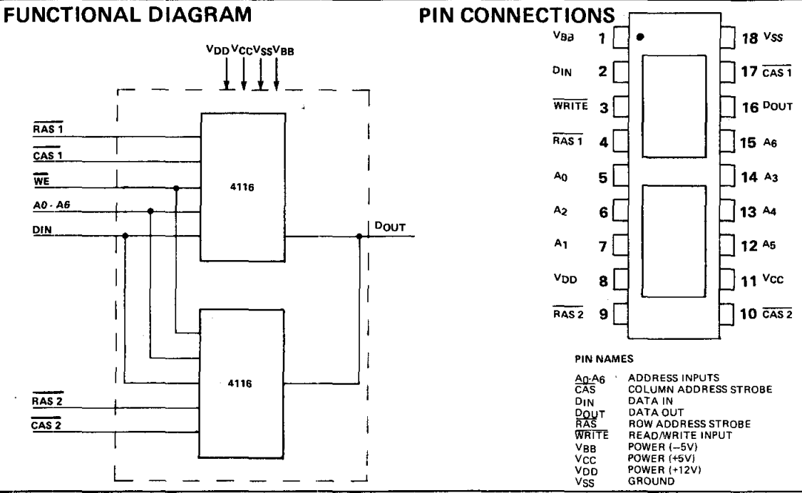
Which IC speaks is chosen by which of the pairs of address strobe pins you clock in – RAS1 or RAS2. You want to make sure to complete a full transaction before trying to select the other chip in the package, because there is actually no protection whatsoever against both 4116s trying to drive the data-out pin at the same time. ↩