Power Surprise with the ADAM
Tags: computer coleco coleco-adam colecovision fujinet power-supply repair pickups
One of the most useful peripherals for the Coleco ADAM is the FujiNet. I got the FujiNet for my CoCo in a previous entry, and it rocks. Adding one simple PCB turned that machine from a generally-useless lump with expensive cartridges, into a very fun computer with online cross-platform multiplayer games, easily updatable software, and expensive cartridges. Would it be just as good on the ADAM? Yes, but somehow I still ended up designing a whole new PCB.
If I’m honest, the biggest motivation for getting the FujiNet is to be able to help test this platform. ADAM has a lot of complexity, between all the peripherals it supports and the platform’s native port of CP/M, and testing new features and regressions often falls on only a few members of the team.
Long term, I also wanted to figure out if I could make a TetriNET client using the Z80 chops I learned making a RAM tester for the Coleco ADAM in a previous entry. Don’t get excited: that’ll have to wait for awhile.
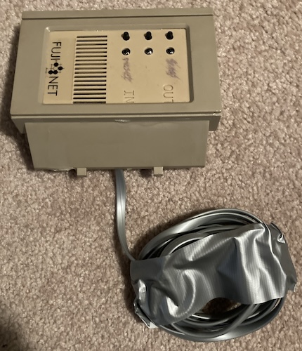
Not wanting to build anything, I went and asked on the Discord if anyone was making them. Henry Rietvald had an older one that he had already made up, and even modified for internal use, and sold it to me for a ridiculously low price. Thank you, Henry!
Installing it
Because this had already been modified into an empty tape drive bay, I had to replace my “blank” tape drive bay with this module. First step is taking the top off the ADAM, which requires no tools.
Inside here is the expansion bay. If I had a RAM expansion card, it would go in one of these bays. Notice how one tape drive connects to two six-pin connectors inside the ADAM. They are staggered, with two pairs 1A/2A at the back, and 1B/2B closer to the front.
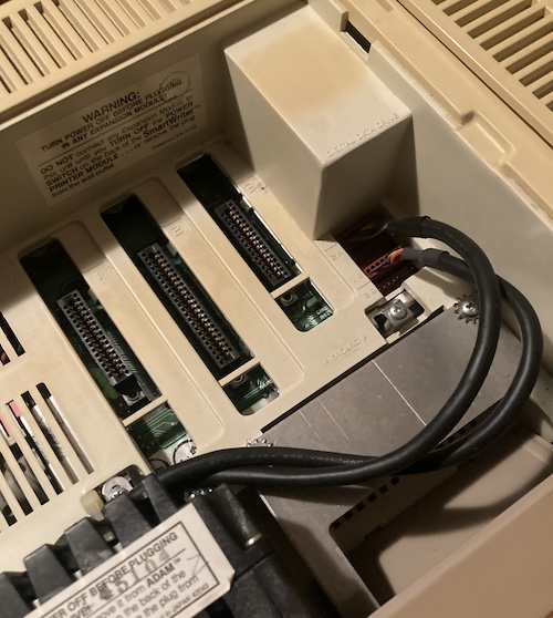
I then removed two screws, and pulled the blank tape bay out. I put the two screws back in for safekeeping, but didn’t snug them in super tight. Then I installed the new FujiNet drive bay the same way, being careful to line up the mounting tabs properly.
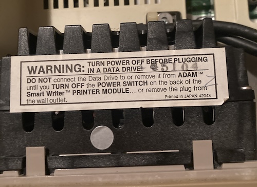
The sticker on top of the tape drive warns me not to plug and unplug it from the motherboard while the ADAM is turned on. I bet someone figured this one out the hard way.
The FujiNet connects using the ADAMNet external bus, which happens on a 4p4c modular connector. I talked about this for awhile in the keyboard section of the previous article, so take a look over there if you’re really curious.
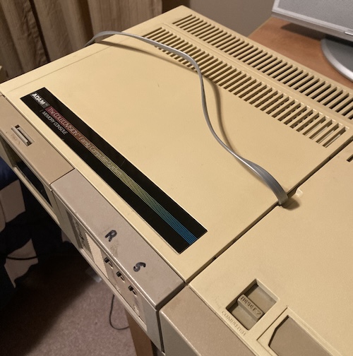
However, I now needed a way to get to this external bus. The closest connector is on the side of the computer, so I snaked the flat phone cable through the finger gap in the expansion bay “hood,” and then over the top of the computer.
Once I accomplished this, I realized that I am probably actually supposed to route the cable out the cooling fins in the bottom of the case. This would be good enough for testing, until I can figure out a cleaner solution.
Maybe I can make some kind of expansion adapter that uses the two six-pin connectors inside the ADAM? It’s possible those are “hardcoded” in some way to only be tape drives. A project for another day.
Disaster Strikes
At this point, I was ready to test this sucker out. My ADAM was going to finally get on the Information Superhighway. And then I knocked my custom-built power supply off the desk and broke it.
Why did my power supply fail when I did a little thing like “drop it on the floor?” There’s lots of blame to go around. The power cord is too short, which means using this computer has always been a little bit of a challenge involving wedging cables in the right spot and keeping the super-light power supply from being pulled off the desk by its own cords.
The damage wasn’t too bad, and thankfully it wasn’t energized at the time of the disaster. Two ferrule crimps had failed, which made me the most worried of the whole thing. If I hadn’t crimped those things properly in the first place, this whole supply was probably a ticking time bomb as it is.
Of course, the 3D-printed plastic case was obliterated. Although I’m no expert, I suspect that the layer height during printing was a little bit too ambitious. Now it was splitting along the gaps in the layer lines in several places like old deck wood.
All three screw holes for mounting the Meanwell RQ-50B had snapped off at the bottom of the screw, as well as all the screw holes around the periphery holding the power supply case together. The screw holes holding the lid also fell apart as soon as I touched those screws.
I started gluing things back together, but soon figured out that it was a losing battle, as the layer next to the freshly-repaired one would just splinter instead, and all the screw holes around the case were torn out and wouldn’t reliably handle new torque.
Remember when I said up above that I didn’t want to have to build anything for once? Sometimes the universe makes other plans.
Opportunity Strikes
Now I had an opportunity to make things better. I decided I would splurge a bit and go get a nicer injection-moulded “project” enclosure for the Meanwell, put a much longer power cord on this thing, and refresh all the crimps. At the end, I hoped that I would have a more reliable power supply. As it stood, the old homemade power supply was taking away from my enjoyment of the ADAM, rather than making it easier.
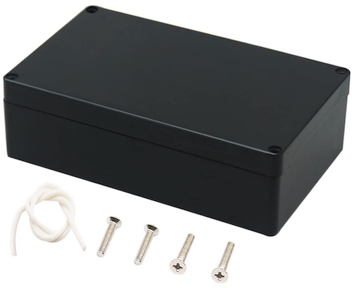
The one that I picked is a “Zulkit” waterproof enclosure (200mm x 120mm x 56mm) from Amazon. Being waterproof is not too important, considering I am about to cut a giant hole in the side of it, but it comes with a very stinky gasket that fits into a groove in the lid. This, combined with the fact that the mounting screws are isolated from the cavity inside, makes the enclosure watertight, if you’re too prissy to simply slather the thing with RTV like the world’s worst sandwich artist. It is unclear exactly what the immersion depth is that the waterproofing on this enclosure is rated for, but if you’re trying to use the Coleco ADAM inside your homemade carbon-fibre billionaire submarine, you have bigger problems.
These enclosures have mounting bosses on the inside, but they’re designed to accept a standard mounting plate, which is what you actually put your stuff on. Unfortunately, the mounting plate is not included, and they don’t even give you the measurements. Those measurements are supposed to be on a PDF linked from the product page, which is not the case on Amazon. Even after looking around on the manufacturer’s page, I wasn’t able to find them.
When my new enclosure arrived, I took it apart and measured the holes. It helps when things are obviously a round number, as the 100mm and 90mm hole spacings were. Meanwell also provides in the power supply’s datasheet some decent (but not turn-your-brain-off easy) dimensions. I’m still a rank amateur at using a digital caliper, but I was able to rough in the dimensions and improvise a plate that could hold the RQ-50B in its place.
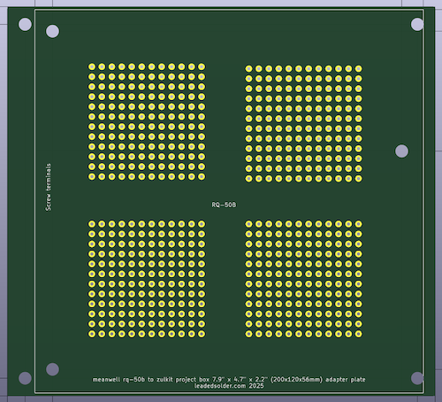
Naturally, I found it easiest to work in KiCad, the only CAD software that has ever actually made sense to me. This was the project that convinced me that I probably do need a 3D printer, because it’s somewhat annoying to order five of these suckers and wait a few weeks. A laser cutter would be much more useful, though (hint to anyone out there who is looking for someone to send a free laser cutter to.)
To try and make the $3/board price “worth it,” I added a relatively useless prototyping area, so at least I could use the four leftover boards from my minimum-size run as more experimental PCBs down the line. Of course, I printed out a test piece on paper before I sent the order away. Who do you take me for, some dude who makes a lot of dumb mistakes on PCBs?
The chances that anyone else on planet Earth will try to combine this exact model of Meanwell with this exact model of enclosure is low. That said, there’s probably a really good chance that the moulds for this enclosure have been passed around all over the world, and there’s several thousand of these cases getting made every year under a bunch of different names. I can’t be sure without measuring the internal mounting dimensions, but it sure seems to be a pretty common size.
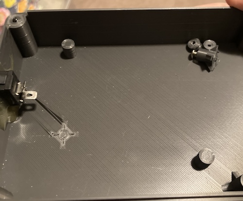
Once it arrived, I put the whole thing together, and found that I had indeed made a dumb mistake on a PCB.
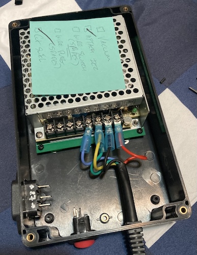
Cheapness bit me in the butt again. I wish that I had made the PCB the whole length of the case, and placed the RQ-50B in the middle, because that would have given me a lot more options for mounting. As it was, the shielding of the RQ-50B got in the way of me getting a screw into the two rear holes properly. This meant that the PCB was only attached with the two front screw holes, instead of all around the board.
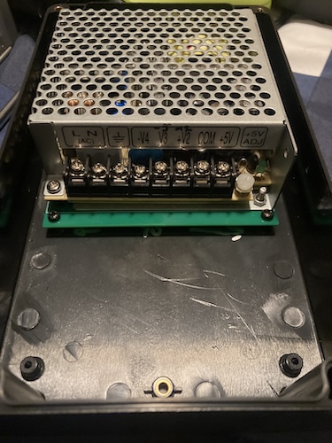
Although I’m generally gentle with my things, it’s not good for it to constantly be levering on the centre holes with the supply’s considerable mass, especially considering the fate of this Meanwell’s previous home. Spending a few extra bucks on the mounting plate would have saved me some grief.
Now it was time for the connectors. First up is the IEC power connector. Since I hate hardwired power cords, this is the perfect chance to make the power cord detachable – and let me choose the length of the cord depening on where the ADAM is getting used.
Of course, an IEC power connector needs a rectangular hole. I know how to drill round holes, but my drill bit box did not contain any rectangular bits.
I decided to appropriate a technique from model car building. On one of the YouTube channels I watch about it, Mini 4WD Condele1 Base, often has to cut holes in the plastic bodies of cars.
He uses a pin vise hand drill to drill all around the perimeter of the desired shape, and then cuts between those new “stitched” drill holes with a side cutter in order to form the larger shaped hole in the panel.
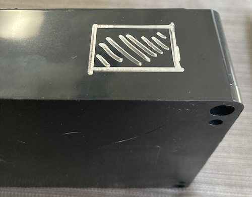
I did the same thing. After measuring the exterior of the IEC and then cutting a template in cardboard, I marked it on my project box in silver Sharpie. Then I started drilling around the inside of the markings.
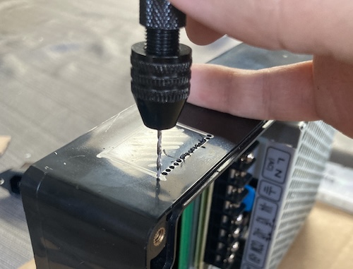
This took awhile, about 20 seconds per hole. Unlike the nice rubber handle on the Tamiya pin vise in the video, my cheap AliExpress pin vise has only a nasty knurled grip that cut into my thumb as I was endlessly turning. I also created a ton of plastic dust and chips, which I scooped up using a sticky lint roller brush.
Next time I’ll just use a drill press. Someone send me a drill press.
Once I had holes all around the perimeter, I grabbed my cheapest and nastiest flush cutter and started cutting. But… the flush cutter was not deep enough to reach all the way through the thick walls of the case. I could only snip the very outer layer of holes. It would seem that styrene car model kits are a lot thinner than 5mm-thick waterproof ABS plastic enclosures.
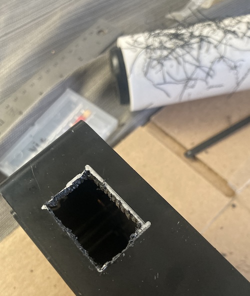
Eventually, I just ended up using a box cutter to “punch” this out crudely. Probably the safer thing to do would have been to throw this in the vise and then use a thin chisel to knock it out, but nobody was maimed severely by this heinous misuse of a tool.
After all this, the IEC connector didn’t quite fit. That’s because I cut on the inside of the marks: it’s always easier to take material away than add some more in. I grabbed a triangle file from my pile of files, and spent another ten minutes laboriously carving away until the IEC connector fit.
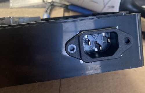
Nice.
For the power switch, I started off by eyeballing the outer diameter of the switch. Looked like it was about 3/4”, so I grabbed a 3/4” step bit and went to town. Unfortunately, it turns out that it was just a little bit larger than 3/4” – there’s a teeny-tiny tab on one side of the horizontal axis to keep it from rotating – so I had to finish the job with some file work anyway.
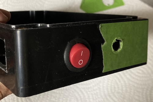
In a project like this, it’s always worth saving some money. I heated up the old strain relief in some warm water and then jammed it into another hole cut by the step bit, which fit with some struggle.
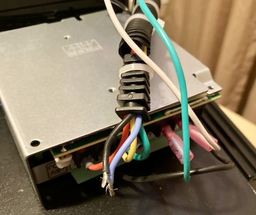
Making the harness, however, was a big pain. I wanted to reuse all the wiring from the last time, but wrap the entire length in heat shrink so it would look nice and professional. Unfortunately, I had a lot of trouble pulling all that wire through the heat shrink.
What worked eventually was to solder all the wires in the cable together, then solder a long “lead” wire to the end of them. That way, I could pull the “lead” wire through the heat shrink, and then pull the cable through it. This looked… okay. To be honest, I wasn’t super happy with it, and it caused a bit of kinking on one of the wires near the strain relief as it got twisted. But it was in there.
Once I had that end sorted, I could remove the leader wire, and shove the whole thing through the strain relief. Then I ran out of ring terminals after breaking a few due to my crappy crimper/stripper.
After more arrived, things came together. Rather than use self-tapping screws to hold the IEC connector on, I used a generous glob of clear RTV sealant. Was that a really good idea? Probably not, but it seems to be holding. This time, I actually thought far enough ahead to have gloves and a clamp. Maybe I am becoming a grown-up after all.
A quick check with the multimeter (use the pointy probes!) showed that all the voltages were appearing where they should.
Testing the new old power
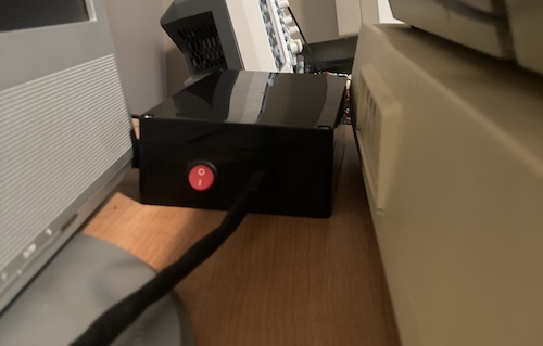
Although I’m disappointed in how the “heat shrink cable” turned out, I like how this box tucks neatly in behind the ADAM “Memory Console.” It’s way less sketchy to set up than before, which means I’ll use the ADAM much more often.
That said, I think there is still some annoying finagling with the various cords that need to go into this sucker. This enclosure’s shiny plastic still slides around a bit on the crappy laminate of the desk, so I am going to put some sticky furniture feet on it when I find where my hoard of them has gotten off to. “Room for minor improvement in usability” is a lot better than being grumpy every time I have to dig it out and use it, which is where I was before.
After connecting everything up, I flipped the switch. I noticed right away that the composite video output is still sort of noisy, with diagonal jailbars everywhere. This is not unexpected, because we haven’t changed anything electrically about the giant switch-mode power supply that’s attached to the system. Between this and the video noise when the tape drive is going, I suspect the ADAM needs a review of bypass caps and other filtering, if not additional grounding.
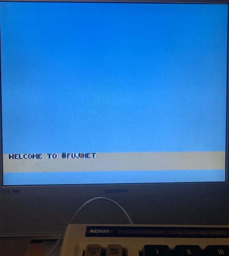
Who cares about junky video? It’s FujiNet time. That’s what I meant to do awhile ago, at the start of this interminable post. Once the FujiNet was ready, it came up with a welcome banner:
And then it started trying to connect to a wifi network that it had remembered from before it was shipped to me:

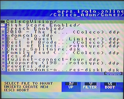
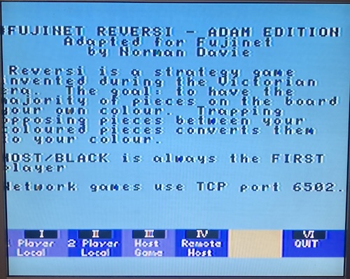
I couldn’t figure out a way to cancel this process. Once it eventually timed out, FujiNet Config asked me what network I would prefer to use instead. I configured it with my local network and we were surfing the intertubes in no time. My first stop was the Irata Online archive, where I was able to grab a FujiNet-enhanced version of Reversi.
That’s right, instructions about how to forward TCP ports on an 8-bit computer. We’re through the looking glass here, people.
Unfortunately, I only had the keyboard plugged in, and hadn’t gotten my ColecoVision pads out of the closet yet. Anti-climactic to the max. Playing internet Reversi would simply have to wait for another day.
Conclusion
Phew. That “having to make a whole new power supply” really chewed up the word count in this post, didn’t it? In the next article on the Adam, I’ll be diving further into the FujiNet, with the goal of booting some arbitrary code from a TNFS server on my local network. Maybe we can make some improvements to Badam without having to burn a ROM.
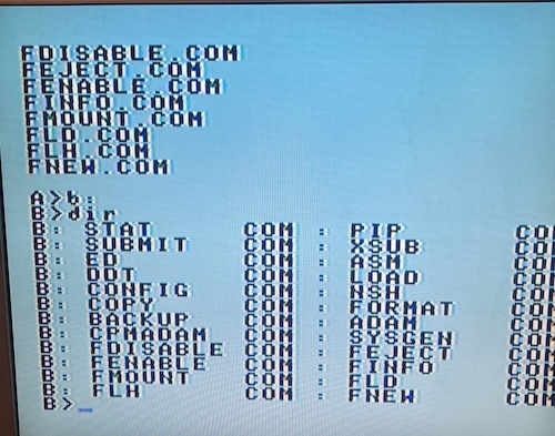
In the meantime, I’ll be playing with 40-column CP/M!
Thank you very much to Henry for the kind sale of this too-cool gadget. Thank you also to everyone on the FujiNet team for making it possible for one of America’s least-beloved personal computers to download videogames over the internet.
And thank you for reading! See you next time.
-
A Japanese portmanteau for Concours d’Elegance, in this case basically a show and shine for model cars. Some of them are really cool! ↩