Fixing the Bad ADB Mac LC's power supply
Tags: computer apple macintosh macintosh-lc pizzabox capacitors power-supply corrosion repair
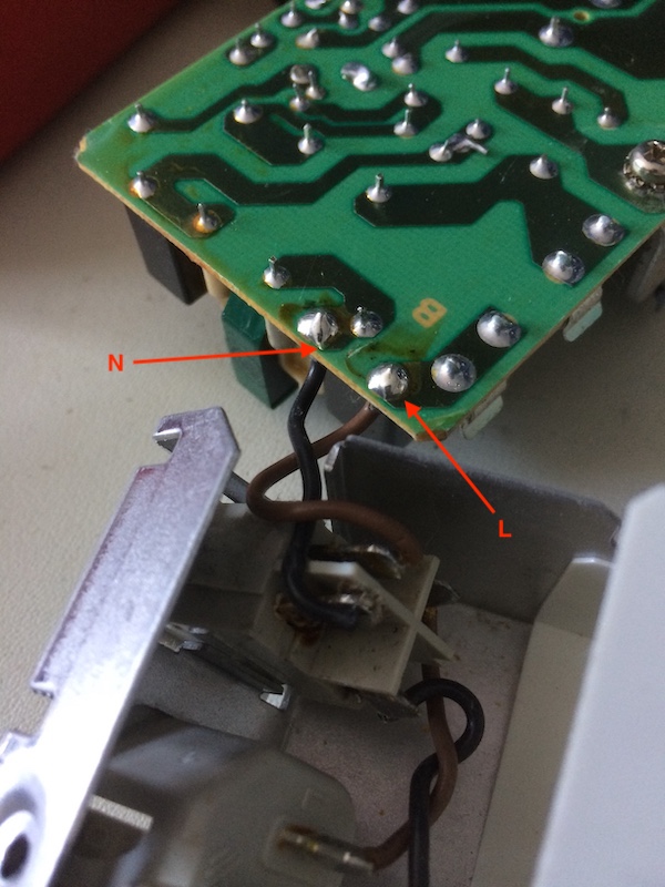
Now that I know that the computer wasn’t horribly killed by my recap job and repair of all those broken traces in the ADB input system, let’s take a brief moment to recap that original Astec power supply from the “bad” LC. And fix the video!
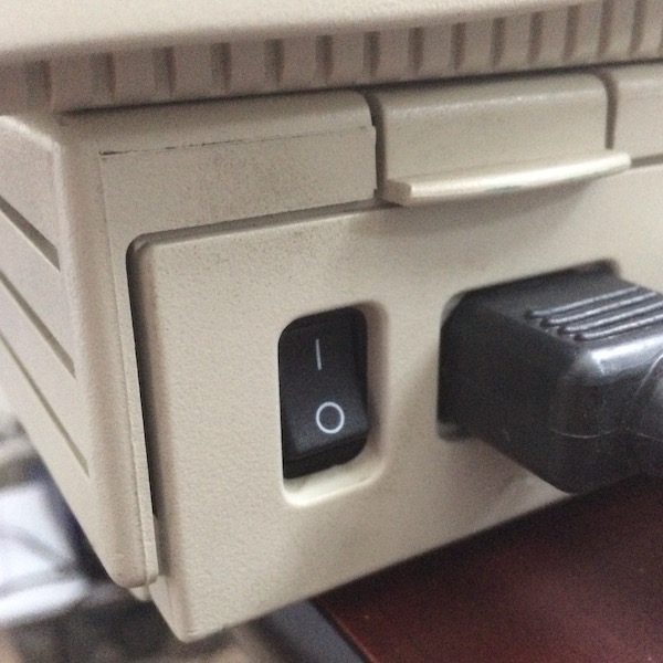
Since I already mangled the switch by attempting to desolder it, there was no real harm in dismantling the power supply entirely, desoldering the wires from the board this time, and then knocking the switch out the back.
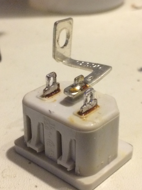
As everyone told me, this is a pretty standard toggle switch. The inscription on the side reads:
250 VAC T100 12A
8550VB
ARCOLECTRIC ENGLAND
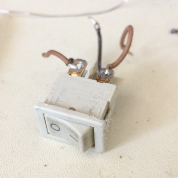
It turns out Arcolectric is still in business, but they got bought out by another company in 2016 (Bulgin) and had to change their awesome name. The “8550VB” family comes in a vast array of variants, one of which - the T8550VBAAA - was available from Digikey for two bucks. “T” indicates a solder terminal, and “H” seems to indicate some kind of push-on connector one. The cut-out dimensions listed are 19.3 x 12.9mm. As a bonus, it may or may not light up.
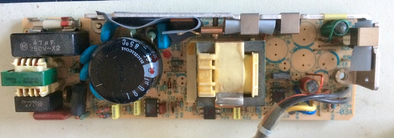
While I had the PSU open, I decided to pull the electrolytic caps out of it (what a journey this is becoming!) Good thing, too, because every single one of those capacitors had leaked at least a little electrolyte. It’s a hard life being a power supply…
Astec PSU caps
| Cap | Capacitance (µF) | Voltage (V) |
|---|---|---|
| C21 | 2200µF | 10V |
| C18 | 2200µF | 10V |
| C17 | 120µF | 10V |
| C20 | 120µF | 10V |
| C19 | 1200µF | 16V |
| C23 | 1000µF | 10V |
| C22 | 470µF | 16V |
| C11 | 47µF | 25V |
All of these caps are rated to 105°C, and considering the power supply does not have active cooling, I replaced like for like.
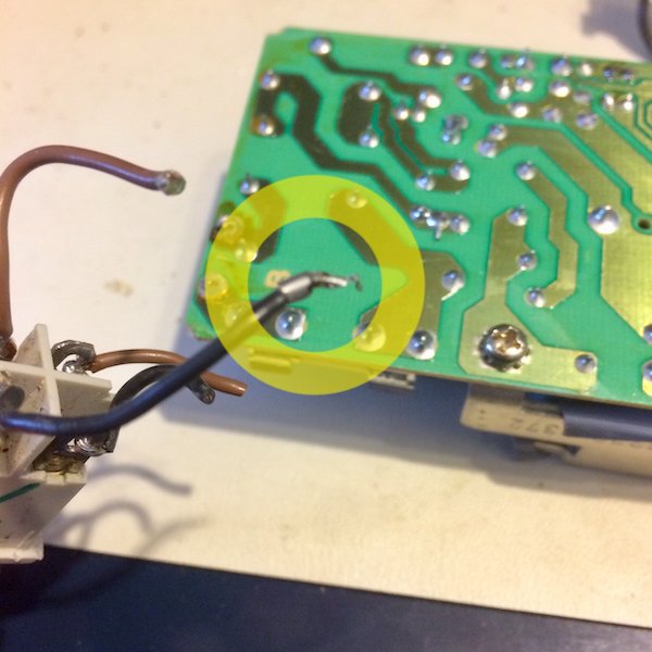
C22 and C11 were the worst visible leaks. C21 had a blown out bung but no obvious leakage. This was a fairly easy recap job; all of the caps practically fell right out of the board once they were introduced to the soldering iron. Thanks, single-sided boards!
I had a little bit of trouble getting enough heat into the pads to do a clean soldering job of the new pads. A bit more flux and cursing took care of it. I’m guessing there was a small amount of corrosion there.
C17 and C20 are unusual super skinny super tall caps.
I did not replace the large mains capacitor.
Switching Tracks
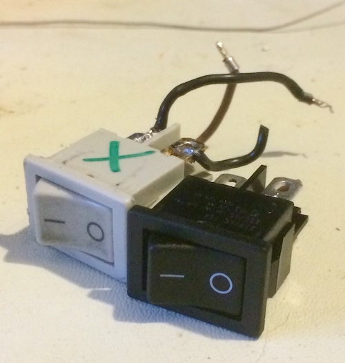
When the new switch arrived, I was elated. Other than colour, it is a perfect match to the original switch. Plus, the side of the switch said something about “illuminated.”
I couldn’t make out the markings on the original stranded wire to figure out exactly what gauge they were, but it looked a little bit thicker than the 24 AWG I had on the bench. To be on the safe side, I eyeballed the replacement wire to 20AWG.
The original wire had a little pin crimped onto it where it went into the board, possibly for ease of machine assembly. I didn’t have an exact replacement pin on hand, so I ended up crimping it into a Dupont male pin that looked pretty similar except for length. The resulting pin didn’t fit through the hole in the board, though, so I took the pin off, twisted the wire and just soldered that to the board.
The replacement wire on offer only came in black and red, rather than black and brown. Also, the new wire insulation was this modern soft heat-resistant silicone instead of whatever the original wires had to make them rigid.
Here’s a Plug
After using like a gallon of flux and two meters of desoldering braid, I was able to save the power plug for re-use. I guess this must also be a way more heat-tolerant plastic than the switch, because I definitely did not treat it with much more care and it didn’t melt.
It took forever to clean all the flux off, and it took awhile to desolder, so definitely not the most time-economical practice. A new one would have run a little more than a buck on Digikey, but I wanted revenge after the power switch melting episode. And I had that revenge.
I ran the new wires a little long, so I could easily solder up both sides without having to keep working around the shell. This meant I had to kind of bunch them up a bit when the board actually went in, so I tried to keep them away from the sharp solder joints on the underside of the PCB where the insulation might be punctured. On the terminals, I also applied some heat-shrink, since even though I was fairly confident in my solder joints, it never hurts to be a little extra safe when it comes to mains power.
You’re Grounded!
Once the power supply was back together, and I tried putting it in the machine, I noticed two things:
- The power supply doesn’t quite fit as snugly as it once did, requiring too much force to seat.
- The power cord won’t fit into the plug on the back anymore.
Once I looked at the plug, I saw just how badly I had screwed up. Because I had bent the metal on the case so much trying to remove the melted switch, it didn’t settle back straight, and the plug couldn’t fully seat either. That meant its little mounting clips were sticking up in the path of the cord:
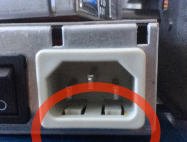
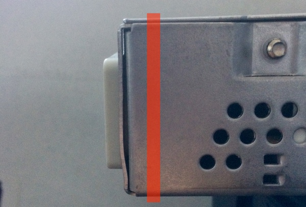
I realized I had warped the metal while trying to get the switch out. At the time, I didn’t think anything of it, other than the ugliness, because it clicked in firmly and felt good with no wiggle. But I was deluding myself.
To fix this, I would have to tear the entire thing back apart again, risk melting another switch while desoldering it, pop out everything, and then bend the sheet metal until it was flush. At least it would give me another chance at doing the wire bundling better - a small comfort.
Discouraged, I threw everything in a corner and didn’t think about it for awhile.
Then, I pulled it out of that corner, and got a big hammer.
It’s Hammer Time
Pounding the fascia of the power supply back flat wasn’t hard at all with the right tools. I went over to a buddy’s blacksmithing shop and asked him to use his brass rod, safety squints, and smallest hammer to see what he could do to work the wow out of the metal.
He was disappointed I wouldn’t let him completely dismantle the supply back to a flat sheet of metal and redo it from scratch, but I just wanted to get the project done.
Once I was back at home, I put everything together. It was another annoying exercise of making wires long enough to solder outside the case, but short enough that they wouldn’t get in the way. I had also forgotten what screw went where, but I eventually triumphed.
Let’s fire it up!
Unfortunately, the power switch did not actually illuminate. I don’t know if there is something special I have to do in order to make that work (the datasheet is unclear), but in neither “on” nor “off” configuration did I see any light of any kind coming out of the switch.
There was a “bong” sound, and eventually the computer comes to life with a Happy Mac. It’s alive again! Now just to figure out how to fix the video…
That syncing feeling
Now that we know from the TDK supply recap project that the power supply was not to blame for the crappy video, let’s do some experiments to see if we can get this thing to actually be usable without me pulling my hair out at frequent video desyncs.
The IBM ThinkVision monitor tried its absolute hardest but just couldn’t get the job done. I’m actually embarrassed at how long it took me to think of pulling out the 1970NX for this project - somehow my brain has become convinced this is the monitor for Amigas and Japanese PCs, not something as pedestrian as a Macintosh.
Yet, after many experiments with the often-failing IBM monitor and a completely-failing Samsung, I grew to suspect something about the LC’s sync is just too slow for the modern LCDs in my pile to latch onto. Let’s see if the 1970NX and its super-broad input tolerances can make sense out of it.
I love you, 1970NX. Never leave me.
It works. At first the monitor’s autoscaler had a very strange amount of horizontal distortion at the top of the screen, but a mode switch and an autotune fixed this right up.
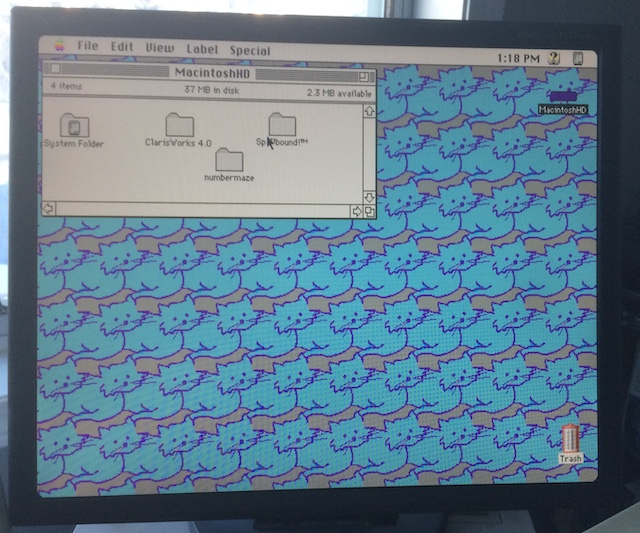
Let’s look around the hard drive. That tiny 40MB drive is almost completely full!
Maybe Spellbound! works. I used to be pretty good at this.
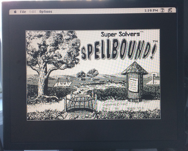
It’s just in black and white (it must be an older variant of the game, reused by whatever school had this before from their Classics, SEs, and Pluses) but it’s playable. Slow, but playable. Was this game always this slow?
Ah well, let’s see if we can get some dirt on the machine. Let’s start with About This Macintosh…
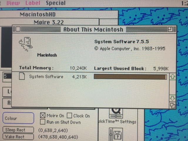
It’s got the full ten megs, which is surprising considering they never bothered to upgrade the VRAM so I could have 8-bit colour video.
However, two very interesting things are happening here:
- The System Software has lost its icon, probably because of a corrupt desktop database. Time to rebuild the Desktop!
- The LC doesn’t “know” that it’s an LC. This one’s weird; usually the System Software reads a Gestalt ID to identify the computer. Often you see this revert to “Macintosh” if the Mac is newer than the operating system, but System 7.5.5 is definitely newer than a Macintosh LC. You can always use a utility like Wish I Were… to lie about it, but I’m not sure what the mechanism for calculating it normally is. I had assumed it was just a value in ROM up until now…
The floppy drive also works great, although the “auto-insertion” grasp is not as crisp as it should be and you have to kind of fumble it into the drive. I’m guessing the drive is a little gummed up over years of disuse. Even so, it managed to format and read floppies without any problems, so I’m going to call it “working” until I see evidence to the contrary.
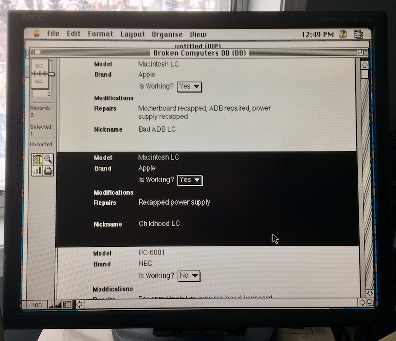
Now I can finally get organized and keep track of my broken computers in a database rather than a big ol’ spreadsheet. Why not use ClarisWorks 4, the gold standard in database technology? It’s never been surpassed.
Repair Summary
| Fault | Remedy | Caveats |
|---|---|---|
| Power supply switch damaged. | Replace power switch. | |
| Power supply has leaky caps. | Replace caps. | Did not replace ‘main’ cap. |