Hearing the PC-6001 out
Tags: computer nec pc60 pc6001 repair
When I first set up the PC-6001, I had to bring it back to life by replacing the shorted tantalum capacitors on the motherboard’s power rails. It’s such a great little machine! After some more testing, however, it became obvious that I was getting no sound out of the poor little thing.
The PC-6001 has this great AY-3-8910 sound chip in it - one of the classics - so getting to hear it is a big part of the enjoyment of the platform.
Of course, I checked the volume control first before cracking the machine open. I learned my lesson in that from the PC98.
Let’s look at the schematic and see if there are any electrolytic capacitors that might need work. If the tantalums got hit hard enough to short them, it stood to reason that their less sturdy friends in the amplifier circuit may also not be too healthy. There are six good candidates, and - just our luck - a test point at which I bet we can see a pre-amp audio waveform on the scope.
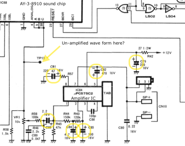
If you can excuse a bit of hypocrisy on my part, I decided to just shotgun these caps rather than break out the oscilloscope or measure them prior to replacement. The test point isn’t accessible with the heat shield in place, so I’d have to work my oscilloscope leads around a live mains transformer to get the test point in question.
On top of that, I found out that my capacitor tester on my multimeter only goes up to a pitiful 200µF (although all caps under that range did test out OK), and I have not yet bought one of those amazing el-cheapo ESR testers.
I mean, there’s all that, and there’s also a lot of suspicious-looking corrosion on the cap leads and visible leakage on the other side of the board.
With that in mind, all eight electrolytics in this area are going to go live on a farm. Keen eyes will note there is a ninth electrolytic here, which is unmarked, but that’s one of the brand-new tantalum replacements from last time.
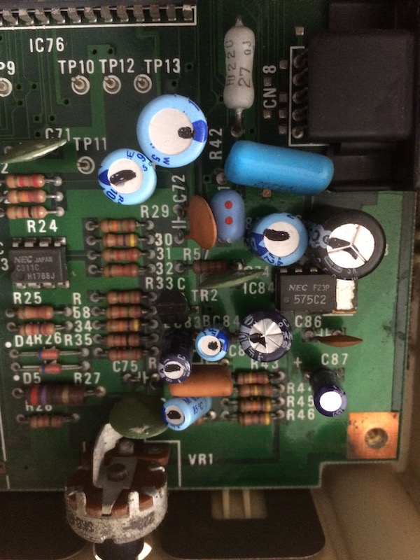
Check out how big R42 (near the top) is. That little 575C2 amplifier chip must be thirsty.
The odour of fish didn’t go away the entire time I was doing this. I had the unfortunate luck of picking C79 as my first victim, whose tiny body let off enough stink to be smellable outside the room with the door closed.
I had a lot of fighting to do to free C81 and C82, but eventually I prevailed by doing multiple cycles of calmly adding more solder and sucking it away into the gun.
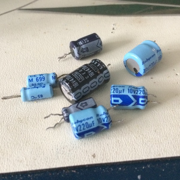
Here’s the caps and their values. Notice that there is some variance from the schematic; the schematic also wasn’t accurate that all of the power-rail caps were 22µF, so don’t assume this is the exact same as your PC-6001, especially if you have an American PC-6001A:
| Capacitor | Capacitance (µF) | Voltage (V) |
|---|---|---|
| C73 | 220µF | 10V |
| C79 | 220µF | 16V |
| C81 | 220µF | 10V |
| C82 | 470µF | 16V |
| C83 | 10µF | 16V |
| C84 | 2.2µF | 50V |
| C85 | 100µF | 16V |
| C88 | 2.2µF | 50V |
All of the caps I removed were rated only to 85°C; I spent a few cents to replace them with 105°C because of the poor cooling under the RF shield. Cheap insurance, but also I don’t like to mix temperatures in my spare-capacitors bin if I can avoid it.
Some of these capacitors I didn’t have on hand, so the board sat for a few days while an unseen, infinite machine of package droppers and kickers worked hard to get me my Digikey order.
When removing the motherboard this time, I also found an extra screw left behind, under the lower RF shield. I’m not sure where this came from (I don’t recognize it from any of my prior services), but my guess is it’s for the empty threaded hole in the upper RF shield where a third-party expansion card can be screwed down. However, the hole in the case that would be punched out for that card is still present, so what happened here may remain a big mystery. UFOs are probably to blame.
Testing 1, 2, 3
I wasn’t sure what sounds a PC-6001 should make, so I used the PC-6001 support in MAME to try out a quick test. What I found was that the PC-6001 should make sound on at least three events:
- Using the
PLAYcommand to play simple music (e.g.PLAY "ABCDEF") - Typing
- Error beeps (thankfully not as annoying as the PC-8801)
Unfortunately, none of these worked. And the video quality wasn’t any better!
Thinking the volume pot might be dirty or otherwise scratchy, I tried wiggling it while playing music in a loop, but nothing I could do seemed to make the sound work. Neither the internal speaker, nor the RCA jack on the back (which switches off the internal speaker) worked.
Well, I knew it was a gamble when I decided to shotgun caps. Sometimes gambles don’t pay off! So what’s next?
Scope The Dope
Through an awkward amount of contortion, I put an RCA cord into the sound output of the PC-6001 (which should disable its internal speaker, according to the schematic) and then held the hook precariously on the plug while trying to dial my trusty-but-rusty Tek 2246 in. I love firing this thing up, mostly because of the cool future noises it makes, but I don’t love so much the amount of desk space it takes up and my constant irrational fear of damaging it by twiddling values out of range (“OUCH!”)
What I saw wasn’t what I expected. The output waveform was very very small - 0.2V - and looked identical whether the computer was playing music or not. I expected I would at least see the square sound waves, even if they were very small and unamplified. This didn’t look like anything at all. Was the AY-3-8910 dead, and the amplifier chip sitting there, waiting for its friend to tell it something?
Software Isn’t Real, It Can’t Hurt You
My next approach was to see if there was some way I could interact with the AY-3-8910. Maybe I could bang on a few of its control registers, and listen to see if it would respond to me with something resembling a sign of life.
To that extent, I went to a trusty BASIC reference from P6 enthusiast Hashi - Google Translated, of course. And even better, he also provided a great I/O port map.
If you’re unfamiliar with I/O ports on the Z80 (as I was), you can think of them as sort of an alternate memory map. If the Z80 toggles the IOREQ line, then it’s expected that the bottom eight bits of the address lines will be used to find I/O ports and peripherals. Eight bits means 256 ports - that’s a lot.
In the case of the PC-6001, you can find four I/O ports relating to the AY-3-8910.
| I/O Port Address | In/Out? | What’s it do? |
|---|---|---|
| $a0 | Output (from PC-6001) | AY-3-8910 register address |
| $a1 | Output (from PC-6001) | AY-3-8910 output data |
| $a2 | Input (to PC-6001) | AY-3-8910 input data |
| $a3 | Output (from PC-6001) | AY-3-8910 inactive |
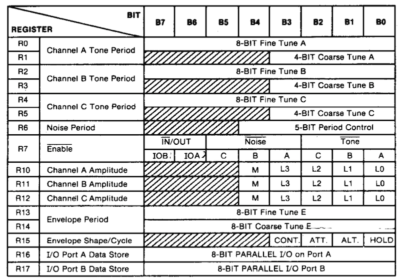
There are 18 registers on an AY-3-8910, including the tantalizingly named “I/O Port A Data Store” and “I/O Port B Data Store” that the AY-3-8910 datasheet claims does not impact PSG operation.
You can use the INP function and OUT keyword to read data from a port and write data to a port, respectively. I decided to write a little BASIC program to print out all the registers, using the knowledge I now had.
10 PLAY "ABCDEF"
20 FOR R=0 TO 17
30  OUT &HA0, R     ; choose which AY-3-8910 register to look at
40  PRINT INP(&HA2) ; read the value of that register
50 NEXT R
If I ran this a bunch of times, because the PLAY command is ‘asynchronous,’ I would see a few of the registers bounce around on both MAME and the real hardware. However, we don’t know if this is really coming from the AY-3-8910 is sending, because they could just be what Z80 is saying to it at the moment.
If I stacked up PLAY calls, one run of the program would wait until the music from the last one finished. Surely that means the PC-6001 is listening to the sound chip, so that it knows when the song is still playing, right?
Not necessarily - in theory the BASIC ROM could easily maintain a queue of “notes” to play, and call itself with a timer interrupt every so often to come back and feed the next note in. Something like this:
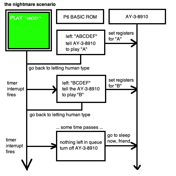
This would wreck this method of diagnosis, because this means there is no need for bidirectional communication between the AY-3-8910 and the PC-6001’s Z80 in order to play music. If this is the case, then using software to check if the “dumb” AY-3-8910 is even working is impossible - its only output is the speakers, and the PC-6001 runs the entire show from timer interrupts and an internal queue.
To really test, I need a bidirectional source that we can write into, do something, and then read back to make sure that the chip is storing it and responding to me. The I/O port registers seemed like a natural choice. Unfortunately, no matter what I wrote into the r16 and r17 I/O-port registers, I only ever got 255 back, on both MAME and real hardware. Running other commands involving the sound chip would produce a different stuck value at r16, but it would still be stuck, even if I wrote back to the register.
After a few hours of scratching my head, I began to wonder if I was actually reading and writing properly. The BASIC manual had examples of using OUT to mess with the sound chip, but not INP. Did I need to do some kind of dance to put the chip in “read mode?”
Defeated, I decided to open the machine and expose the heat shield so I could get TP13. There had to be something I was missing.
Snap Crackle Pot
I took a long look at the volume potentiometer when I got the top off the machine. I’d idly fiddled with this pot before, but this time… I also noticed that the top half wiggled loose, while the bottom half stayed behind.
That ain’t right.
It looks like someone had hit the very prominent rear volume knob and cracked the potentiometer behind it in half. This happened either in storage, or (more likely) during the shipping from Japan. I remember that this machine got stuck way in the bottom of the box, up against one of the sides. That’s the junk life for you.
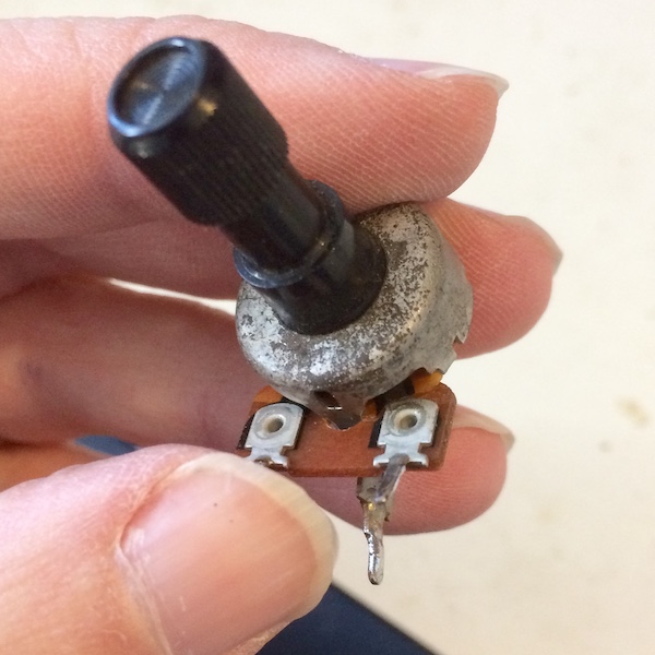
I tried pushing down hard on it with my finger to see if I could re-establish the connection and get sound, but it didn’t help. This 30-year-old vintage Alps volume pot has probably resisted its last current.
Was it actually completely disconnected, though? It looks kind of like part of it is still attached, otherwise it would be bouncing in the up-and-down direction, too. To find out, I took the motherboard out again.
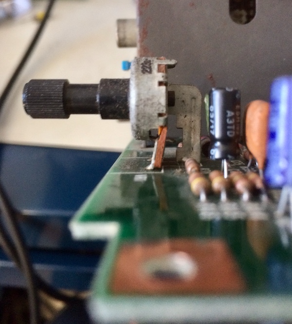
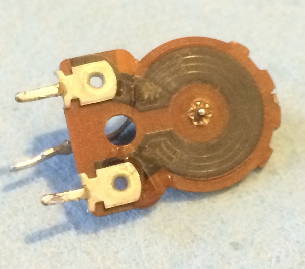
From the side, it sure looks broken.
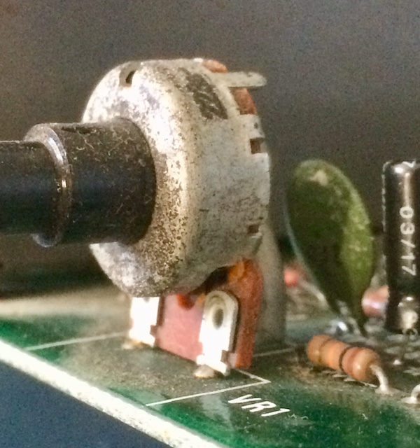
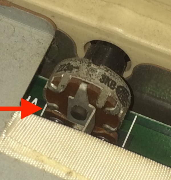
Looks even more broken from the front. The little contacts that go from the wiper to the left and right pins are completely severed.
I desoldered the pot. There was a bit of a fight getting the holes cleared in the front two pins. The two halves of the potentiometer have definitely gone their separate ways.
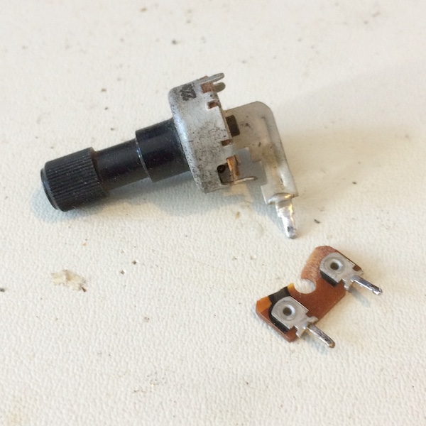
I can hold the pot together, and it looks like it is okay, but the trace remains severed. To test, I clamped this thing into my multimeter and tried to find any resistance values at all, but no amount of pinching and wiggling would re-establish contact.
I don’t think super glue will fix this problem. Maybe I could un-crimp the back housing of the pot, completely dismantle it, solder that stuff back together and try again, but something about the black carbony-ness of these traces makes me feel like solder is not going to stick. This might be a good application for wire glue or another kind of conductive paint.
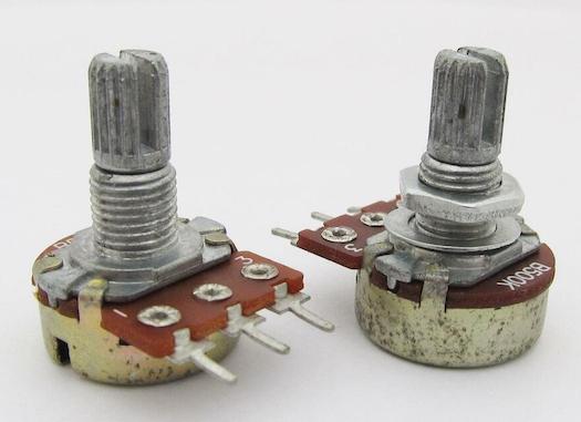
For now, I decided I would replace the pot with a nice new one. Where can we find a 10K pot with this oddball footprint? Most of the pots I’ve seen have just been three pins in a single row, like this:
To make things worse, I found out from testing with my multimeter that it is actually a 3K pot, not 10K! The I/O magazine schematic is wrong again.
That certainly explains the “3KB…”
Arts And Crafts Hour
Not able to immediately find a replacement pot, I decided to take this one apart. This is perfectly in line with the Leaded Solder philosophy of “it can’t get more broken.”
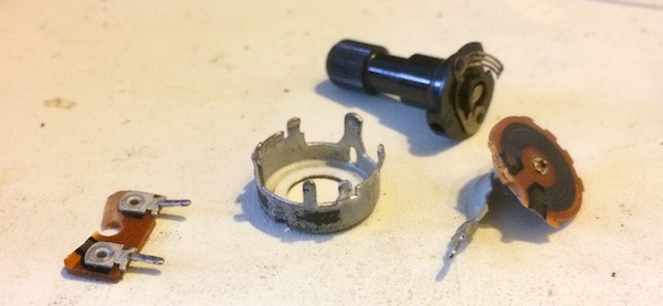
Taking this apart was annoying but not difficult: I used very small pliers to bend the crimps on the back up until I could slip the backing out on one side. With the internals revealed, I begin to feel that a repair is much more possible.
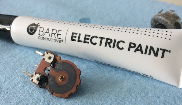
Through the magic of super glue, I was able to at least return this to one component. Of course, super glue is not reknowned for its conductivity, but I also was not yet sure if I could solder to this resistive paint, whatever it is.
I ended up going to the local electronics store and picking up a tube of conductive paint. They had a few MG Chemicals things, but they were out of stock, so I grabbed Bare Conductive’s Electric Paint, which I’d never heard of before. The 10mL tube cost $13, and lots was left over, which makes me wonder if it might be useful for repairing WonderSwan Colour power buttons on the cheap.
I tried to put it in the sections of the track where my multimeter probes could detect resistance, but it’s a little hard to control with the paint tube’s applicator tip. I did a bit of finishing work with a q-tip before it dried.
The box said I had to wait fifteen minutes for it to cure, but it was more like a half hour. It seemed to dry to a sort of dull black carbon-y appearance, but most importantly it crept into the glued-together cracks, which I hoped meant that there would be conductivity.
On the first test, one leg had good conductivity, but the other one did not. After inspecting it under some strong light, it seemed like I didn’t use enough paint and it had pulled apart from itself. I did a few more rounds of adding small amounts of paint and flattening it out with a q-tip, until I could get a resistance reading with my multimeter between the two front terminals.
I was a little surprised that the stop-to-stop resistance was higher than the 3kΩ I expected - it went up to 4.05kΩ - but considering the alternative is “busted,” I was fairly happy. The more I thought about it, the more I was hoping that the specific value of resistance didn’t matter too much for a volume pot: judging from the wear that was on the resistive track before, this thing spent most of its life at 100% or 0% volume.
Even with the extra ‘build’ created by the thickness of the paint, the pot wipers still slid from end to end without much difficulty. I checked the case of the pot for continuity to the legs, and thankfully that extra paint thickness also did not cause a short.
I added a little bit more super glue to the back, in the vain hope that it would provide a bit of structure to keep the PCB from cracking again. After letting that dry, it was time to re-apply the crimps that hold the case together.
It took me much longer to crimp, because unlike dismantling a broken pot, I was now carefully re-mantling (is that a word?) a working pot. Luckily, the crimps all seated with pressure from my bare hands, and a little tap with the pliers to make sure they weren’t coming loose any time soon.
After I crimped the back on, I did another quick test from the front legs to the rear leg, and found a range of 0.02kΩ to 3.33kΩ on my multimeter as the knob turned. I will happily accept an 11% error on this repair.
Let’s Test
It was a little hard to get the pot into the holes in the motherboard, and I didn’t want to apply much force or heat to it. Once it was in, though, it held pretty tenaciously. It now makes sense to me why there’s the little protective tape behind it on the heat shield - that was once a cushion to keep owners from damaging their volume pots in this exact fashion.
I erred on the side of ‘not enough’ solder for the back pin, and just barely kissed the fronts with a dash of solder as well.
After the pot was in the motherboard, I put the computer back together again, and tested it out.
Twisting the pot, I eventually figured out what way to turn to make it louder (when you’re facing the keyboard, turn the knob left - “righty tighty”) and then heard the glorious sounds of keystrokes bouncing through the internal speaker.
I quickly whipped up a BASIC test program, and…
Now that is some quality music right there. I can finally remove the last sticky note on this PC-6001, and say conclusively that everything is fixed. Well, except for the kana button, but I’ll fix that when I get better at reading and writing Japanese.
Both the internal speaker and the TV-out RCA audio work, but the P6’s speaker is much louder than the dinky one in my Sony PVM9L2. Even so, I’ve never been so happy to hear chirpy square-wave music in my life.
I love this little machine, but what’s next?
- I bet the quality of the composite video could be improved by checking inside the RF can on the motherboard for worn-out parts and tweaking some trim pots.
- It would be nice to have more RAM and a better way to get data on and off the computer without using tape-cassette emulators.
- Maybe write some kind of music composition program, so I can actually find out if I can use all three channels of the AY-3-8910 with this wiring design.
For now, though, I will happily enjoy it.
Repair Summary
| Fault | Remedy | Caveats |
|---|---|---|
| Sound doesn’t work. | Reattach volume pot to its own legs, repair potentiometer circuit with resistive paint. | May not be a sturdy repair if damage occurs again. Volume levels might not be the same as original (additional resistance.) |