The X1turbo can see again
Tags: computer sharp sharp-x1-turbo video homemade-hardware
Now that the Sharp X1turbo has been convinced to start up again, it’s time to get some video out of it by constructing a cable so it can talk to a more modern monitor. Yeah, that’s right. No ugly dongle PCB this time!
Just like on the PC-8801mkII, the video output is a TTL-level digital RGB without any “intensity” signals. This means I can reuse the design from my PC-8801mkII “colour video adapter,” which is just a bunch of 150Ω resistors on the RGB output pins to drop the voltage down to the 0.7Vpp that a VGA monitor expects. Since my NEC 1970NX monitor is tolerant of basically every imaginable video input I can throw at it, this is enough for my needs.
If you don’t have a 15kHz-capable monitor, another cheap-and-dirty option would be to use an XOR logic gate to combine the horizontal and vertical syncs into a composite sync signal, and then feed the signals into a GBS8200-style upscaler which can tolerate TTL signals, although the X1turbo’s sync is so weird that this reportedly still needs a GBS-Control addition to the board in order to make it versatile enough to hook up.
The X1 turbo Z is a whole different beast, as it adds lots more colours, and a different cable will need to be made for those folks lucky enough to own that computer.
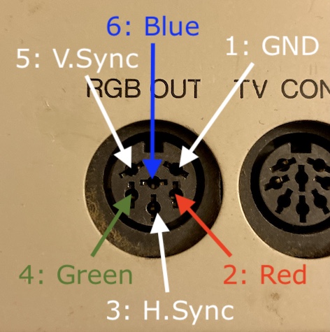
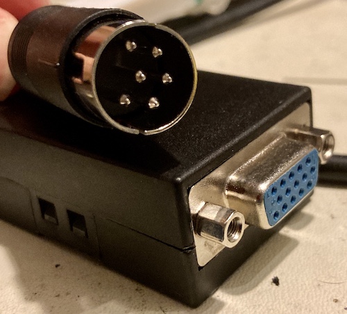
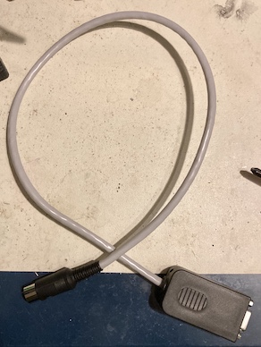
The connector on the X1 is different from the PC-8801mkII. Where the PC88 uses an 8-pin DIN, the X1 only uses a mere 6-pin, 240° DIN. Since I couldn’t easily find a 6-pin DIN cable like I did for the PC88, I made one using a CUI SD-60 male DIN connector, and it fit the port like a dream.
Here’s the pinout, as described by this great archived Japanese-language enthusiast page:
Assembly
Since I had to make a whole new cable anyway, I decided to ditch the clunky PC88 colour video board with its 8-pin DIN footprint, and just build everything into one clean cable instead.
Soldering up the 6-pin DIN connector was the usual group of frustrations, but I’ve gotten a little better at planning my approach out in advance, so I didn’t ruin any connectors this time. One pin did slide forward a little bit in the melty plastic, but that’s what I get for not using a potato.
The cable is a solid-core Ethernet cable from a big box of it that I bought years ago with the intention of making just this kind of cable. It works alright for this purpose, but can be occasionally frustrating as the outer insulation likes to “take a set” and refuse to stay where I put it. I’m not sure there’s actually anything better to use.
My big tips for building a cable using this technique:
- Tin the wires,
- Pull the plastic sleeve insulation way back to expose as much of the inner wires as you can to work with,
- And make sure the “strengthening” plastic rib in the centre of the Ethernet cable is removed before trying to solder it to the DIN. It’s already difficult enough to keep the cable from returning to its “coiled” shape without the extra jagged plastic fighting you.
I still have some trouble with keeping the DIN from “splitting” the two halves. I suspect there is a trick here with the side alignment tabs that I simply don’t know, or maybe I put too much tension on the wires inside the boot.
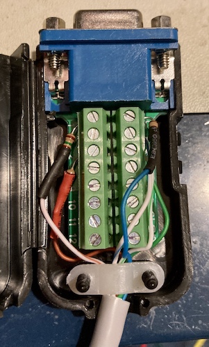
On the VGA side, laziness won out and I ended up using a cheap(-ish) AliExpress VGA breakout connector rather than solder the tiny wires to a cramped VGA HD15 connector. The hood even had plenty of room for the resistors!
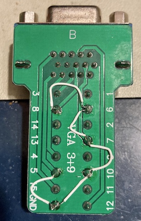
I decided to solder the ground wires together under the breakout PCB rather than use the screw terminals. This made it a little cleaner top-side, though I had a lot of trouble cutting and stripping Kynar wire that short, and whatever solder it was assembled with spattered all over the board when I tried to remove it and add new leaded stuff.
I’m oddly proud of this. Well, maybe not so much the ground wires, but nobody has to see those.
Testing
To test, I plugged it into the RGB out port, and plugged the VGA side into my long-suffering NEC 1970NX. The X1turbo is sort of infamous for being picky about which monitors it will work with - even a lot of 15/24kHz monitors compatible with the PC-88 and Amiga just can’t find a usable signal.
Here it is displaying the boot screen of the X1turbo:
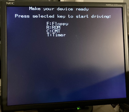
The monitor detects a 24.8kHz negative horizontal sync, and a 55.4Hz negative vertical sync, which made it think that it’s looking at a 720x400 picture. No wonder lots of other monitors have trouble with this!
What’s Next?
Unfortunately, I still need some more stuff before I can test to make sure the colours are correct. As you can see, there’s only white text… I need a program that shows all eight of the colours to make sure they are in the right order, so I can be sure I didn’t transpose the red, green, and blue wires.
Off to BASIC, then, right? Not so fast…
The X1 series of computers deliberately does not contain HuBASIC in ROM. This was done to provide a memory map that offers as much space to the Z80 as possible, without paging, when not using BASIC1. Since it’s not in ROM, that means the BASIC interpreter has to be loaded from tape or disk - and this computer did not come with any disk drives. A basic first step will be to add those drives back in.
Second, it doesn’t make any sense to be able to get into BASIC – or anything else – if I don’t have a keyboard. At the time of this writing, X1 keyboard prices are an order of magnitude greater than what I paid for the entire machine. I’ve got a little trick up my sleeve, however, and I’ll hopefully have progress to report on that front soon.
For now, though, I think we can officially check off this X1turbo as no longer being destined for the trash heap. Although it’s probably pound-puppy syndrome, I’ve really fallen for the little guy. It’s so close to being a usable computer!
-
I don’t know how much of an advantage this lends to the X1; I’m told that the later PC-88s have a mechanism to put the computer into “64K RAM mode,” which disables the BASIC ROM from decoding, when the MMODE register is set. Maybe this was a better selling point in the earlier era of the Sharp MZ computers. ↩