All A-Keyboard for the Sharp X1turbo
Tags: computer sharp sharp-x1-turbo homemade-hardware homemade-software keyboard keyboard-converter
Even though the X1turbo is working again, it’s not enormously useful right now. Sure, the boot screen is pretty, but there’s so much more to the entire experience. In order to take another step along the road to it becoming a functional computer, I’ll build a keyboard adapter.
If it seems like I have a lot of keyboard projects on the go, you’d be correct. It appears to be one of the most common failure points, maybe because keyboards not only have lots of parts to go wrong, but are also desired by thick-walleted collectors who apparently want to use a mediocre mid-80s Japanese-layout keyboard with dirty switches on their work computers. Either way, キーボード is one of the Japanese words I have become very good at reading.
Keyboard Adapter Projects: The Tumultuous History
Without putting too fine a point on it, I’m not actually very good at finishing keyboard adapter projects. I’ve started a handful, but they all seem to fall apart during the firmware-writing phase.
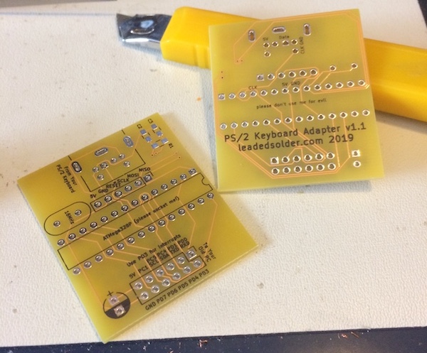
There’s a variety of unfinished adapters already lying around, including spun-but-not-perfected custom PCBs like the one above, that I would like to eventually use. It’s worth pointing out that making these adapter boards didn’t actually save me any money; you can buy fully-equipped Arduino Nano clones for a couple bucks, although getting a PS/2 port wrestled onto them is much more difficult.
In what I hope is the antithesis of the humblebrag, here is a short list of computers for which I have begun but not successfully completed a keyboard adapter project, in no particular order:
- Tandy 1000;
- Nintendo Family BASIC;
- NEC PC-8801 “Type A;”
- NEC Mr.PC (spoilers);
- Mac Plus/128k/512k;
- Amiga 2000/3000 (yes, the Amiga 2500 has one, but only one)
Why the historic lack of follow-through? It turns out that software is boring and hard, and hardware is fun and exciting. Oops. At least there’s lots of half-completed keyboard adapter projects lying around for me to crib code and techniques from!
In order to keep this project going, I decided I would approach the tasks in an iterative fashion, which is a fancy way of saying “setting my sights low.” If it generates keyboard input when I hit the keys, I’ll be happy, and I can update the firmware for all the special cases as I notice them.
I also wanted to avoid leaning on the custom hardware until the firmware was further along, as programming my custom board with a serial adapter can be very annoying compared to just pulling an Arduino Uno clone out of a box. Overall, I wanted to get a functional adapter working with enough capability to write a BASIC program, even if it’s not perfect.
Sharp-ening It
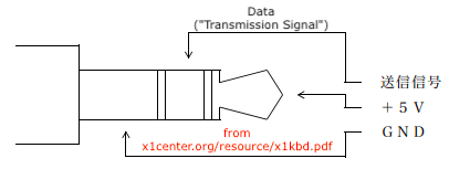
The X1turbo is a little unique, in that it uses a 3.5mm mini-jack/headphone plug for its keyboard connector. I was able to find a Japanese PDF about the keyboard’s signalling and pinout, which helped a lot to figure out which ring went where. Once again, the fantastic X1Center.org site comes through with all the details!
Everyone on planet Earth probably has at least one broken set of stereo headphones lying around. I reached into my junk bin for the cord that I cut up to test the SN76489s I used in the ColecoVision project. It’s got Dupont male connectors on the end of it, which makes it perfect for prototyping using an Arduino board.
Even if I owned a “real” X1 keyboard, I likely still would have to make a new cable, because the keyboard cables often fall apart and need replacement. Be a good excuse to learn how to coil cables, at least.
Try It Again.
As already stated, in order to prototype my approach, I grabbed an Arduino Uno clone from the corner of my desk. I wrote some quick firmware to press and release a key over and over based on the info in the PDF, but something went wrong almost immediately.
Whenever I connected my Arduino Uno clone to the keyboard port and powered on the X1, even without wiring up the +5V, the computer would display “Try it again. Turn power switch on slowly.” It wasn’t any different when I was running it with the Arduino receiving a +5V supply from the X1. What did this cryptic and bizarrely-informal error mean?
I tried the “keyboard” in both the front and rear keyboard jacks. The X1Center website had prepared me to expect damaged solder joints on the keyboard jacks, and the front one did seem pretty loose. Unfortunately, no matter which jack I used, I would still get this error screen.
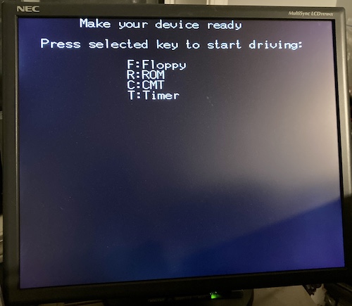
Unplugging the “transmit” line from the Arduino and leaving it floating seemed to let this pass, which made me think it was less of a physical layer problem and more of a logical one. Eventually, I figured out that initializing the output to “high” let the X1’s IPL progress to the “Start Driving…” screen.
I still don’t know what the problem is here; Japanese messageboards mention the error briefly, but seem to imply it is caused by an electrical fault like a dodgy connector. It seems to raise the same error if the Arduino is not powered at all, so maybe it’s the keyboard controller just getting upset that the active-low keyboard is “stuck.”
If you have any idea about what’s happening here, I’d love to hear about it in the comments.
Decoding…
Even though the X1 was now booting, it pointedly ignored my key commands. It was hard to tell exactly what the problem was here. Although the docs seemed to state that the key output is ASCII, sending ASCII sure didn’t seem to work.
To make sure I wasn’t going insane, I checked the MAME source code for the X1 keyboard driver, and it did appear to be sending ASCII to the keyboard input port. T became $54, as you’d expect.
Secure in the knowledge that I had been doing something wrong, I reviewed my code with harsh eyes and noticed that I wasn’t sending the “from key input” flag. Sending this additional flag didn’t change anything at first, but it was definitely incorrect.
Eventually, I went back to Google and found this other page, which mentioned the original x1center documentation, but said that there was no need for a START bit, and that the “state” byte was backwards in the x1center PDF.
I actually had to send the data in this order:
- Header
- From numpad?
- From new key input?
- From key repeat?
- Graph down?
- Caps Lock locked?
- Kana locked?
- Shift down?
- Ctrl down?
- bits 7..0 of the ASCII code of the letter (lowercase
tworked here for me, it has to be uppercaseTif SHIFT is held apparently) - Stop bit
With that out of the way, I can now get into the Timer screen by repeatedly sending t:
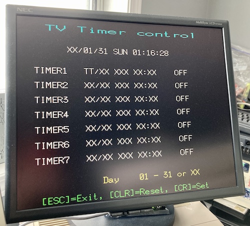
Since I can type one character over and over, that means it works as a proof of concept! Now I just need to turn it into something useful.
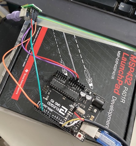
I couldn’t find the little breakout board I’d made for a PS/2 port previously, so after an hour of hunting around my shop, I just sat down and made another from some protoboard and a pin header. It turned out to be a fairly decent little board, although the mass quantity of jumper wires is a little sketchy.
The Firmware
So far, I can type, and that feels great. All I need to do is implement the rest of the keys, right?
However, there’s a little wrinkle. The X1turbo has two keyboard “modes:”
- What I just wrote is “Mode A,” where a single key transition is sent in one huge “ASCII” blob along with accelerator-key (Shift, etc) status;
- Mode B, introduced on the Turbo, where the state of all of the “game specific” keys are sent in a smaller blob immediately before and in addition to the “ASCII” single-key blob, so that game key state can be read more quickly by a video game. It also sends this packet with much faster high/low transitions, presumably because the quicker hardware on the Turbo can decode it better.
Obviously, running pre-Turbo software in “Mode B” is potentially going to cause some compatibility issues, so on the original Turbo keyboard, there is a hard switch to toggle between the two modes. If you read the PDF, there is a note that “Mode B” is only supported well by a small set of games that arrived late in the Turbo’s life, so I didn’t know if it was even worth implementing initially, and in fact most (all?) of the available adapters don’t bother to support the second mode.
Because the keyboard serial is a one-wire protocol, we send data using delays between bit transitions, with similar encoding to how serial data is sent from a cassette tape recorder. I ended up implementing the different packets as C structs, and then writing different transmit functions that would send “mode A” and “mode B” packets.
Building up those packets based on PS/2 keyboard state was a little more work. Previously, I’d used the PS/2 keyboard library for the Teensyduino on the Tandy keyboard project. One potential trap with this library is that you have to use an interrupt-capable pin on the microcontroller in order to read the PS/2 signal, as all of the parsing is done in an interrupt handler. This is why I ended up with (at least) two revisions of the PCB… although I still haven’t finished the Tandy adapter, at least the lessons I learned have made this one go faster and cheaper.
For starters, I just took the PS/2 library’s default US-keymap ASCII decoding and shoved it directly into the output packets heading to the X1. It worked great, except that it didn’t pass along the “break” flag that told me when the key was no longer being pressed. I had to hack it to send a “released” event to the X1 after each “pressed” event. It also didn’t easily handle mapping to kana, graph, caps lock, the number pad, etc. To fix these problems, I’d have to add some special logic to read the queue of raw scancodes and interpret them.
Or, I could go looking for a different PS/2 keyboard library, which is what I ended up doing. The PS2KeyAdvanced library followed the same API pattern as the other PS/2 keyboard library, but sent back a double byte instead of just the character pressed. In the ‘extra’ byte was flag information on make/break/etc.
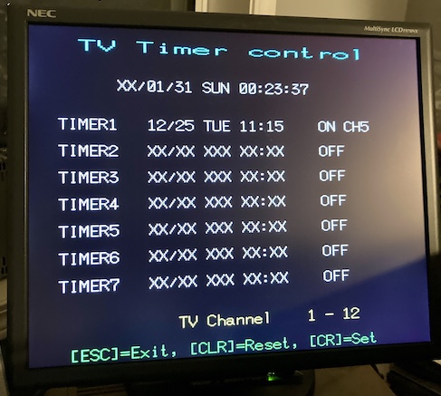
I dropped it in, tweaked some include paths, and suddenly the keyboard seemed to be working great. I could even ESC out of the TV timer options after setting them!
There were a bunch of flaws that I had to modify the software for, such as carriage return not working, only being able to “break” the last key pressed, and a general lack of understanding of how a lot of the special keys (for instance, Return) functioned. Through trial-and-error, however, I think I’ve reached a version of the software that kind of works, even though it meant that I had to tear it down and rewrite it at least once.
I was trying not to over-engineer things up to this point, because I’d learned in the past (and would soon learn again on this project) that keyboard adapters often don’t work in a clean “functional” pattern, and I’d have to move around the code.
For instance, on my Tandy adapter, I had spent a lot of effort to make a code generator for the PS/2-to-Tandy keymapping. I had to throw it all away when I realized that there were cases where:
- One PS/2 keyboard key sends multiple scancodes that needed to be parsed into one Tandy key (e.g. Pause/Break is eight scancodes)
- One PS/2 keyboard key needed to be turned into multiple Tandy keys depending on keyboard state (e.g. backslash is on the number pad on a Tandy, so I have to know if the shift key is pressed, numlock key, etc.)
Having to throw out all that nice fancy code-generation stuff bummed me out, which is a big reason why the adapter got shelved for awhile and the 1000TX hasn’t been usable. I’ll probably restart that project again later, with a full rewrite, now that I know more about the problem. It’s much easier to throw away crappy code than it is “nice” code, so it’s a good thing that I had mostly written crappy code. That’s because in order to deal with just the “make/break” logic, I was going to have to get rid of a lot of it.
The bigger problem is that there was only so much testing I could do using the TV Timer and “which floppy drive?” boot screens. That means it’s not really worth prematurely rewriting the code until I can test it and really understand what the problems with the current stuff are.
To test the adapter, I’d have to get into a word processor, or at least BASIC, to see how the machine responded to my typing. For that, I’d have to actually boot off a floppy, but before that, I’d need to have a floppy drive. My X1turbo didn’t come with a floppy drive, as it was obviously someone’s last-chance parts machine in the past due to the fact it didn’t start up.
My plan for this is to modify the same floppy adapters I built for the PC-8801 to work on this computer as well, and install a Gotek floppy emulator. Then maybe we can play some videogames! Or, more likely, debug the intricacies of the keyboard protocol until it’s rock-solid.
Hold On A Minute, Buster
But wait! What about those cool custom-keyboard-adapter PCBs that you showed off up above?
As I alluded to, there’s a couple problems with those PCBs that have so far kept me from using them to make a cool finished product in an awesome project case:
- Since the firmware is still in development, I expect to be reprogramming the boards many times until I can figure out the secrets of the X1’s keyboard. Unfortunately, as mentioned above, the boards are annoying to program, since they can only be done with a clunky and precarious USB-to-serial adapter. I’ve been using the Arduino Uno clone for development instead;
- A number of bodges had to be made, including some pull-up resistors and a cap for the reset line, so I decided it would be better to run off a new set of “fixed” PCBs, which hadn’t arrived at the time of this first prototype;
- And I couldn’t use the old boards, because, uh, I lost them somewhere in my shop. As you can imagine, it’s somewhat of a mess right now.
Once I can use real X1 software and the firmware is in less flux, I’ll be flashing the firmware onto the boards and releasing the entire whack as open source. With a new entry, of course.
Conclusion
Even though it’s not perfect yet, I’m excited that one of my many keyboard adapter projects has actually gotten to this level of functionality! It always feels good to make something that is useful.