Sharp invites you to enter the Turbo Zone
Tags: computer sharp sharp-x1-turbo power-supply repair
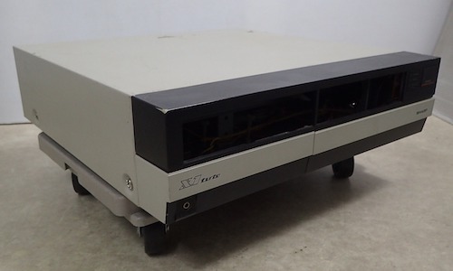
Before the X68000, Sharp had a Z80-based 8-bit personal computer that tried valiantly to compete with the PC-88 and MSX. Actually, they had a couple, but the one that I’m most interested in is the Sharp X1. It combines flash VCR-esque styling, sturdy construction, decent graphics capabilities, and AY-3-8910 sound. What more could you want? Well, you could put the word “turbo” on the front.
A Family History
At the very highest level, there are two “Turbo” X1 model families - the older X1turbo, which this is, and the X1turbo Z, which added additional graphics modes with more colours, high-density floppy drives and FM sound. Unfortunately, the Turbo Z is also very expensive right now (especially if you get it in the stunning automotive-grade candy-apple red paint) and I didn’t know if I would enjoy the computer at all, so I opted to look in the cheaper family Turbo, selecting the relatively base-model CZ-852C. For more info on the Z, you should take a look at blog friend Sean’s excellent documentation of his gloss-black Turbo Z.
To make things even more confusing, there are several later revisions of the regular X1turbo, which added desirable features like YM2149 FM synthesis1. You can check out all the different X1 chipsets on this exhaustive table on the Japanese X1Center fansite.
In my book, the “ultimate” Sharp X1 is the Sharp X1 Twin, which was a Turbo with an NEC PC Engine built in2. It has an X68000-esque tower case, is built like a prototype that escaped from the lab, and nowadays costs about as much as the last used car I bought. Still, I want one.
Introducing… This One
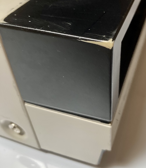
I wasn’t especially looking for an X1 all that intensely, but I had a box already going with some other Japanese acquisitions and decided to put out a lowball bid on this one. Why this one? Because I can’t resist a pound puppy, this poor CZ-852CE X1turbo with no disk drives, no keyboard, case damage, and “does not energize” fell into my lap after a tiny bidding war for ¥1850.
The plan for this repair session is as follows:
- Clean it;
- Get the clock battery out;
- Figure out if it can turn on.
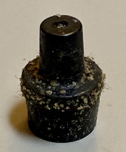
Once it showed up about a month-and-a-half later with a bunch of other projects, my first surprise when unboxing it was that the computer is so big. It’s like the size of a conventional VCR, but I had assumed from pictures that it would be much smaller. I wasted no time in cleaning the case with Windex. It had a light cigarette stink to it, so no sense in risking transferring that to my carpet and furnishings if I could avoid it. There was some sticky rubbery gunk (melted monitor feet?) on the top of the case that came off with elbow grease.
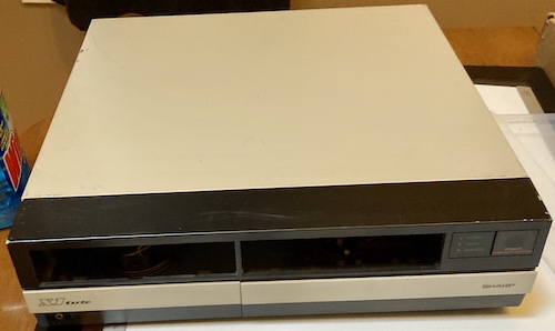
Uncle Grandpa tried to park the X1 after having a two-martini lunch:
After even a little cleaning, the computer had become a decent “fifteen-footer.” I wish they all cleaned up this easily.
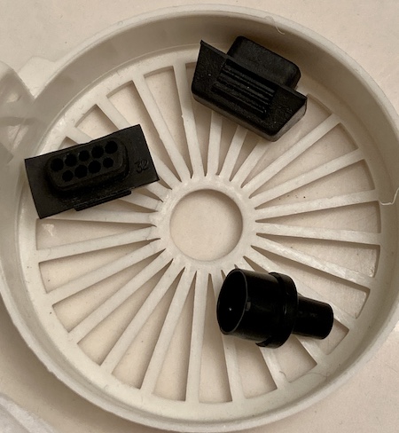
Around back is a different story. The plastic plug for the “CMT” port had grown some kind of crystalline nastiness, and the fancy moulded-rubber joystick-port covers had a bunch of similar gunk. In fact, whatever this is had spread all the way up the back of the motherboard, just past the painted parts of the case.
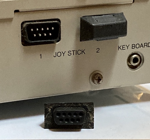
I put these guys in the ultrasonic cleaner with my usual recipe (water, dish soap, and enough oxyclean to bring Billy Mays back to life) for three hours, which knocked all the bad stuff off. I was frankly impressed at how nicely they came out:
Worryingly, the over-moulded rubber insulation on the power cord appeared to have gotten old and brittle. It was difficult to bend the cord, and you can see parts where it has started to separate in the middle.
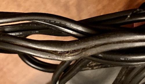
The two poles aren’t shorted to each other (there’s another layer of insulation on each of the conductors even if the over-mould fails,) but it probably wouldn’t take much more rubbing damage to make them that way. This might explain why I’ve seen so many X1s for sale with the power cord completely severed (apparently it’s Japanese shorthand for “I believe this home appliance is super dangerous.”) In any event, I have a perfectly good original two-prong cord left over from when I replaced the X68000’s power supply, so at least I have some spare parts.
Open It! Open It!
I decided I would check inside for any obvious gunk or living things that would cause me to give this machine a time-out for a few weeks inside my garage at winter temperatures. The case comes apart much the same as the PC-88s, but Sharp used little fibre washers on the screws which kept them from corroding as badly to the case metal. As well, the thicker metal of the case itself doesn’t distort like my PC-88s, so it’s much easier to take the case off and put it back on. Already I was starting to like this machine…
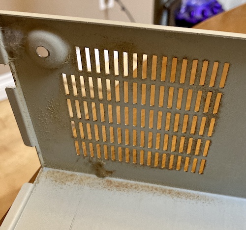
Decades ago, some spiders had built a little home near the fan grille. Aw! They went down the sink. The rest of the inside of the machine is very clean, which is nice to see.
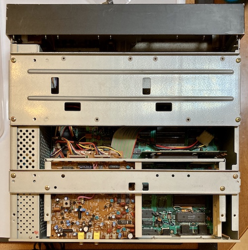
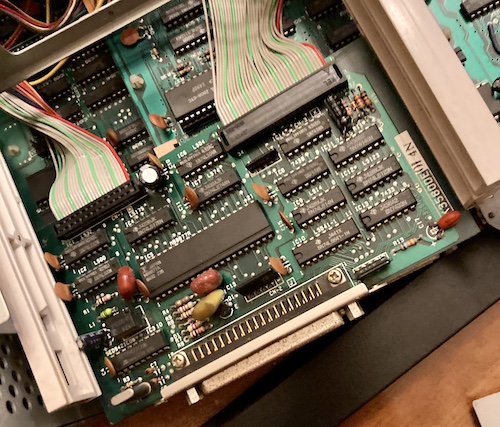
This thing has more internal structural bracing than a rally car. Look at all this stuff! It’s some sturdy-feeling stamped steel. It looked like someone had been in here before me, probably to remove the floppy drives for parts, and lost some of the screws.
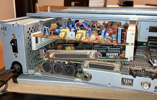
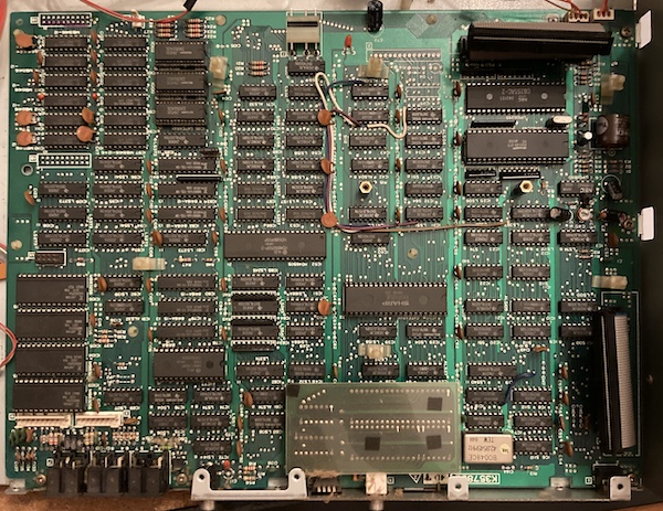
The big single-sided yellow board on the left is the “Telopper3” board. This is sort of a Japanese-ism that Westerners would call genlocking. It lets the X1 inject a video signal into an NTSC TV stream over composite, possibly so you can use it as a titler. I’m not sure what else it could do beyond that, but the original Sharp monitor on the X1 could also be used as a TV, so this is likely used in order to switch between “playing on the computer” and “watching TV” modes.
There are a bunch of ports on the back to control this, including one so you can set the chroma-key colour that will be cancelled on the original signal and replaced by computer-generated video. My long-suffering X68000 ACE also has this feature, but I strongly doubt I will ever use it in lieu of an actual titler.
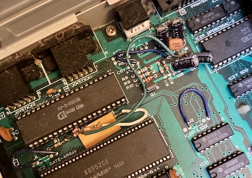
One thing that’s immediately noticeable is this mishmash of bodges near the AY-3-8910 sound chip. I think this is a modification that was done by a hobbyist, because the thick-gauge wire and huge solder blobs don’t look like a factory rework job. I’ll have to reverse-engineer this circuit and figure out what it does later.
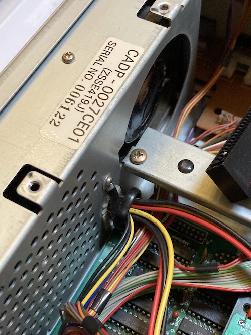
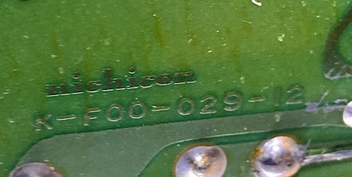
The power supply runs nearly the entire length of the computer, like on some of the PC-88s. It has a really nice-looking fan with some expensive-looking tinwork. The little grommet that protects the supply cables is the same one that’s on the early-X68000 “Tetris-piece” PSUs, but the PSU is made by a different manufacturer here - Nichicon, rather than Kyosan. Since the power supply’s case appears to be structural to the computer, if I want to replace the power supply, the new one should fit into the same case.
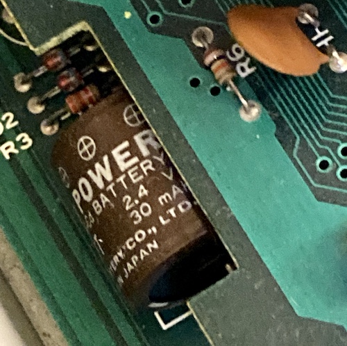
A Yuasa “Memo Power” battery - the same battery as was used in the PC-88s and Tandy 102, PC8300, etc - lurked between the two logic boards. Luckily for me, the negative terminal of the battery looked pretty clean. It’s a little surprising it hadn’t begun to leak, but I also couldn’t get a really great view on it until the top board was removed.
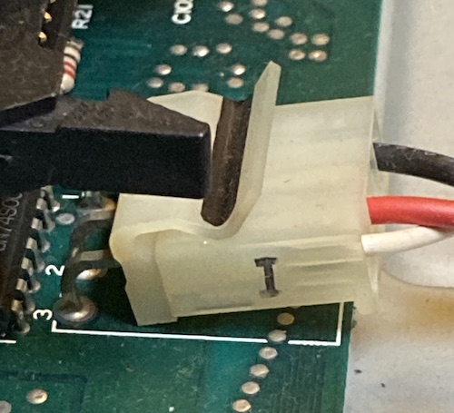
There’s a big three-prong Molex-style connector marked “I” that goes to the topmost of the two logic boards. On the X68000, the “I” connector serves the +5V and ground rails to the main logic board, but it’s only two poles. I was kind of hoping this was just loose or something, and I could easily finger it as the source of the claimed “does not energize” problem.
After removing the back panel (which is held on by a lot of screws) the external floppy drive port fell inside the machine. This is because the port is attached to the floppy drive control board, which had fallen out of its retaining rails. Probably this happened during shipping, and wouldn’t have been a problem as it was still held in place by the back cover, but the potential for shorting the solder joints onto the motherboard beneath made me nervous.
The telopper board had to come out to get access to the top of the floppy board, and unfortunately the other end of the ribbon connectors are soldered in - like on the X68000 motherboard. I ended up undoing a bunch of other cables so I could get enough slack to pull the floppy board out the back and put it back into its own precision-formed rails, then retained it with the back panel after cleaning out the accumulated hair and dust. I think I found the spider that built that nest, too.
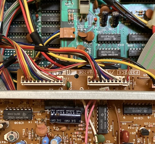
After enough cable pulling, tab-popping and expansion-slot-removal, I found a couple of missing screws, more bodges, and lost some skin on my knuckles. One of the ugliest parts of pulling the upper “I/O board” is that the ribbon cables connecting it to the motherboard have no slack in them whatsoever. I think this was meant to be installed as a unit, though there’s no way you’d ever remove it that way.
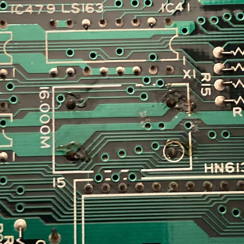
Someone else has definitely been inside this machine. There was evidence of sloppy rework on the mouse port, 16MHz oscillator on the I/O board, and there were some missing screws to stabilize the telopper and floppy boards and keep them from falling out. Nothing serious, but annoying.
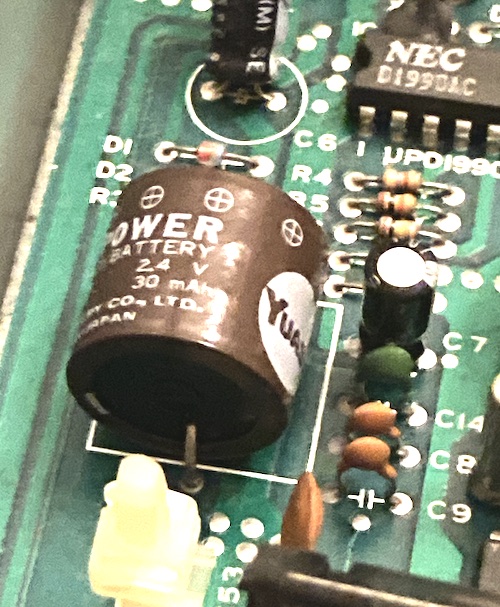
I clipped the battery out and was surprised to find out that it had not leaked at all. On the multimeter it read 0.2V - pretty damn close to fully discharged in my book. The poorly-filled solder joints made me suspect that it had been replaced at some point in the past, and was not the original clock battery.
Stand By Me, When You’re Not On
I plugged the X1 into my 100V stepdown transformer, hit the switch on the back, and then pushed the power button on the front. Nothing happened. Like, nothing. Usually if it’s hitting short protection, a power supply of this vintage would at least spin the fan for a split second before shutting down…
After taking a look around, I determined that none of the power rails were working, except for the lower board’s white one, which seems to be +5VDC standby as turning the front button on and off didn’t change its status.
Seize The Power
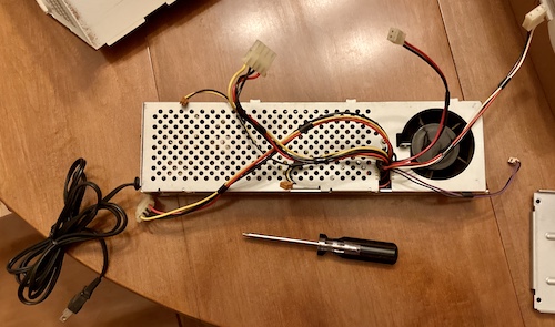
The (massive) power supply comes out once you remove a screw on the rear and the couple of brackets that attach to it. It’s actually a pretty easy design, though I scraped it against the screw holes in the case as I was pulling it out and scratched the nice, shiny plating on the power supply. Hopefully nobody will notice. Be careful and watch the “B” connector as you remove the supply; it’s easy to miss as it’s tucked under the front fascia, has delicate thin wires, and is connected to the power switch on the front panel.
The lower motherboard is really pretty, or at least it would be without all these crazy bodge wires:
Power, Supply Thyself
After removing the power supply, I counted up the unique colours on its wiring harness in order to try and get an idea of what power rails we’d be dealing with. Here’s what I puzzled out between the wire colour and the motherboard:
| Wire colour | Does what? |
|---|---|
| Black | GND |
| Red | +5VDC |
| Yellow | +12VDC |
| White | +5VDC stand-by (Vcc2/CH2) |
| Blue | -12VDC |
| Purple | Front panel power switch (short to black/ground pin = turn PSU on) |
Before testing the PSU, I thought the white line might be -5V and tried to trace it out to confirm, but it turned out to go to places that didn’t make sense (pull-up resistors for the data lines on the 8255, for instance.) After finding a copy of an X1turbo Z service manual on Sharp’s Cocoro Books e-book platform, and stumbling through the terrible mouse-driven interface, I figured out that it was “+5V Vcc2,” or always-on +5V. This is another good lesson that Japanese machines don’t always follow the ATX colour standard, even if they use Molex power connectors.
Unfortunately, I also couldn’t safely use the service manual’s description of the allowable minimum and maximum current per rail. My power supply had lots of differences to a Turbo Z supply, including stuff as obvious as completely different PWM switching chips and optoisolators.
Now that the supply is removed, it was time to give it a good inspection. Based on the seller’s description, I was expecting some obvious damage to the power supply. It’s best to make sure that it’s in good condition - I don’t want a repeat of the Tandy 1000SX incident, because a custom chip from an X1 will be even harder to come by.
After undoing a bunch of non-obvious screws, the inner power supply case can be sort of Tokyo Drifted around the fan and removed. It’s hard to describe; the technique makes more sense if you’re actually there doing it.
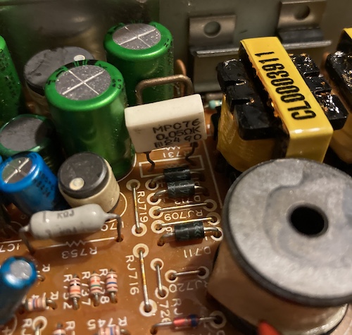
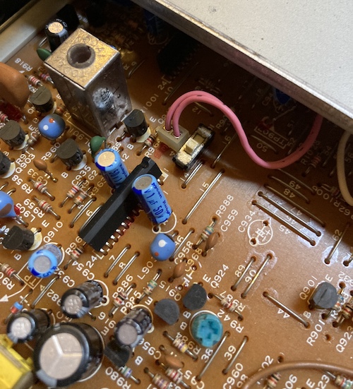
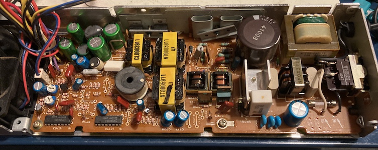
I noticed the giant power resistor R731 (right of the green electrolytic caps, left of the transformers) had been bent over. It was hard to tell if one of the legs had made contact with the leg of a diode directly underneath it, but there was no obvious damage from such. I bent it back upright just to be on the safe side.
I did a bunch of testing over the next few weeks and couldn’t find anything obvious wrong with the supply:
- The prongs of the electrical cord were continuous with the switch, meaning the wall cord itself wasn’t broken.
- The power switch closed and broke continuity when it was flipped from one position to the other;
- None of the wire harness to the computer was damaged;
- Nothing looked obviously burned, bulged, or blown;
- The main fuse was intact;
- None of the power transistors, diode packs, or regulators were shorted from one leg to another;
- Both of the bridge rectifiers tested out properly;
- The diode that R731 had touched wasn’t shorted or open;
- All of the fusible resistors seemed to be “continuous;”
- All of the electrolytic capacitors passed or just barely failed an ESR test;
- The fan turned smoothly by hand and wasn’t seized
After removing the PCB from the case to inspect it (not hard, but annoying with the hardwired wall-power cord) I was able to scope out a few things that were curious.
The bodges on the underside of the board - a surprising amount! - looked pretty rough, with one resistor sprouting blossoms of copper corrosion amidst huge gobs of super-gross, slightly charred, silastic:
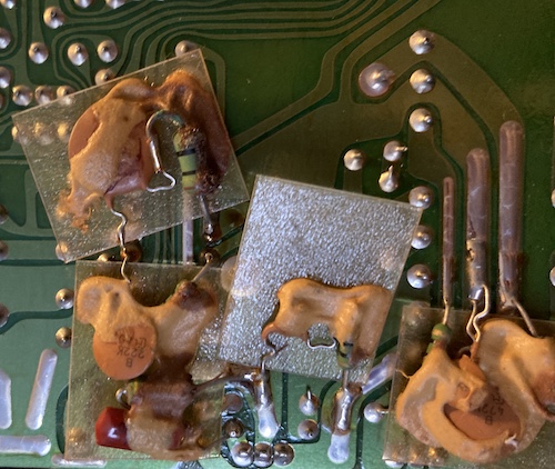
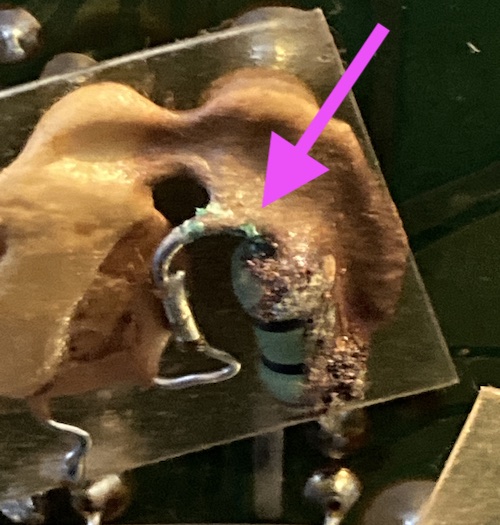
I’ll have to come back and clean this up later, but it tested out fine in-circuit in continuity mode, so the corrosion hasn’t damaged the resistor or broken its leg.
Since I was running out of ideas after a lot of testing, I also bought Hirofumi Iwasaki’s excellent e-book on repairing the X1turbo, but the power supply section mostly focussed on recapping. It did have this interesting and helpful snippet (translated by Google,) which would have been good info to read before replacing some of the caps on the supply:
The low ESR PX (M) is used as the type of aluminum electrolytic capacitor used in the power supply unit of the X1turbo, but if this is replaced with the modern low ESR KY, squeal will occur and the voltage will be unstable.
Indeed, I had PX(M) caps in my supply, so at least I know that part was original. The picture of the bottom of his board had different silastic for the bodges, different coloured caps, and five bodges instead of three. A little surprising that it would be so inconsistent from machine to machine!
I’ll spare you the details, but I spent a lot of time looking into and tracing out the power supply, and so far there seemed to be nothing obviously broken that would create such a big fault.
Oh, Actually I’m An Idiot
You might have noticed that I tested the supply inside the machine, but not outside of it.
Coincidentally, friend of the blog Johnny Blanchard also got an X1turbo at around the same time, replaced the (severed) power cord on it, and then fired it up on video with no load. It seemed to work!
What ultimately pointed me to the real problem, after a lot of Japanese-language Googling, was this Japanese page by Oh! Ishi, which mentions in passing that the protection can be tripped on the +12VDC rail by the inrush-current demand from dried-out caps on the telopper board. Huh?
I thought about it for a bit, and then I realized that if there were a dead short on the +12V rail, it would probably not spin the fan. I got a sinking feeling as I realized that I had only tested for motherboard shorts on the two +5V rails – in my mind I considered it to be the most likely rail to short, as I didn’t realize the telopper board consumed +12V.
Because I took the supply apart, I knew that the standby +5VDC and the full +5VDC rails came from different bridge rectifiers (the “runtime” one is significantly beefier) and therefore are on totally different circuits. Protection could conceivably trip and knock out the +5VDC runtime – but not the +5VDC standby – rail.
Between Johnny’s video and this new info from Oh! Ishi, it was starting to feel much safer to run the supply unloaded, at least for a short period of time.
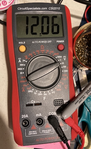
After plugging in the supply to the wall and switching it on, the fan leapt to life and I got a solid +5VDC and +12VDC on the Molex connector. This means that the problem must be on the PC side – the power supply is probably good enough for our purposes.
Through this ordeal, I became much more comfortable with the components and basic layout of a switching power supply, but it still felt like a waste of a few days of “shop time.”
The moral of the story? I should have done better diagostics before opening the supply up and attempting component-level repair. Cutting corners on diagnostics always results in wasted time on the back end.
Who Shorted?
Our Japanese informant was right on the money by blaming the telopper board. When I went to check it with a multimeter, the “C” connector that provides its power input was continuous across its terminals. In fact, it’s so close to a dead short that the meter displayed just 1.3Ω of resistance for the entire circuit! Now that’s shorted.
Immediately, I suspected the nearly 40-year-old tantalum capacitors on the telopper board. I’ve seen dead-shorted tantalums before, and the Japanese machines seem to have a weaker power supply than the stupid-but-burly IBM PC supplies that blow shorted caps off with raw power.
I decided that I would check the function of the computer without the telopper board. All I would have to do is unplug its connector from the power supply.
Update: Later, I would try disconnecting the larger data/signal cables from the telopper board, as I figured it was not a great idea to drive unpowered logic chips, but this was a mistake – it produced no video output on RGB then. It appears that the way the telopper works is to “pass through” the RGB information from the motherboard, which makes sense in retrospect. So I just kept the telopper’s power unplugged, and haven’t noticed any negative outcomes – though I’m certainly not going to run it all day until after I’ve repaired the board.
Of course, without the composite video output of the telopper, I couldn’t simply use a TV to check if the computer produced video. This meant I had to build a video cable to use it with an RGB monitor after all, which I’ll cover in more depth in the next entry.
Does Energize
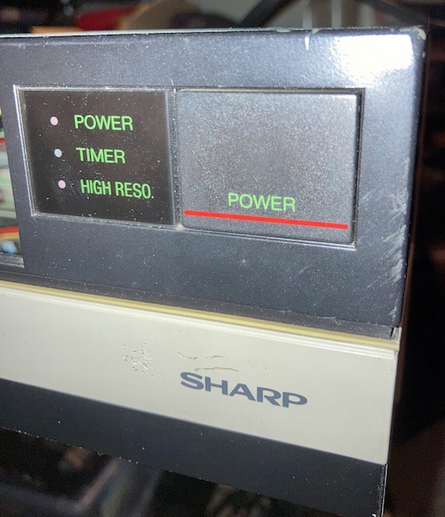
After plugging in the assembled machine to my stepdown transformer and switching it on, I once again pushed the power button on the front. This time, I was greeted with the grumbly noises of the power supply fan, and the POWER and HIGH RESO lights on the front lit up. Hooray! It’s working again.
I quickly scrambled to grab the video cable and tested it out. Other than having to reposition the horizontal and vertical of the output, I was able to get a really nice-looking picture of the IPL (initial program load) screens out of the 1970NX.
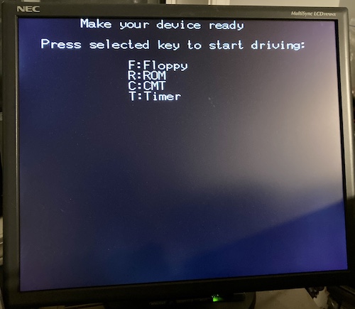
And that’s where the testing stopped, because I don’t have a keyboard! Or a floppy drive, come to think of it…
Conclusion
I really enjoyed getting to grips with the X1turbo so far. It’s sort of like a parallel-universe PC-8801mkII, and I find it grabbing me in the same ways. Now that it’s been saved from the metaphorical junk pile, my to-do list is filling up with the future fun projects that will turn it into a useful denizen of the collection.
Repair Summary
| Fault | Remedy | Caveats |
|---|---|---|
| Gross crystalline gunk on dummy plugs. | Ultrasonic cleaning. | |
| Clock battery exists. | Terminate with extreme prejudice. | Was this useful for anything other than RTC? |
| Only standby power is working; computer won’t power up. | Unplug power to the shorted telopper board. | This didn’t actually fix the telopper board. |
| Telopper board is shorted on 12V rail. | Not fixed at this time. | Use 3-bit RGB output instead. |
| No way to actually use computer. | Not fixed at this time. |
-
I stand corrected on this matter (thanks cuba200611.) The YM2149 is Yamaha’s version of the AY-3-8910 and doesn’t support FM sound. It might have been used in the later Turbos to reduce their dependency on General Instrument. The YM2151, which is FM-capable, was added later in the Turbo Z model, and there were FM-sound expansion cards made available throughout the X1 and X1turbo’s lifetime. ↩
-
Some sources claim that the X1 Twin is compatible with X1turboZ software, but I’m not so sure about this. The turboZ adds a 15-pin analogue RGB output, and the twin does not have one of those. It seems more likely to me that the X1twin is only capable of playing X1turbo software at most. ↩
-
As far as I can tell, the word “telopper” is not short for “television operator,” but instead refers to Telop, which is a kind of slide projector that was heavily used for superimposing title cards and transition effects onto TV and film in the 1940s and 50s. Although I can’t figure out where this particular use began, technical Japanese continues to use this term as a verb for basically any “titler” style operation, such as subtitles. ↩