Do you want to come for a ride in my Jaaaaaaaag?
Tags: console atari atari-jaguar homemade-hardware video
One of the most unloved machines in my hoard collection is the Atari Jaguar. It’s not because I don’t have good games for it, or because it’s not working. No, it’s because the Jaguar came used with only the RF adapter, and I hated setting it up with a TV. After testing it out, and collecting a few games for it, it ended up getting boxed away for a move about a decade ago and hasn’t come out since. And that’s a crying shame.
What’s the best way to use the Jaguar again? By adding composite video! Well, to be more accurate, we’re adding Model 2 Genesis video, because I don’t like making cables and already have a large stock of Model 2 Genesis composite cables lying around. Why not reuse what’s already cheap and widely available? You can get a Model 2 cable for about a buck shipped on eBay, which is much better than over $40.
With all this in mind, the goals for this project were as follows:
- Get this Jaguar to display composite video;
- Try not to solder any cables.
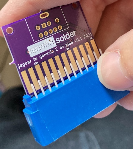
Since the Jaguar’s AV out is a simple 0.1” edge connector, I looked around for a connector that would fit it, and then designed the board so that the connector would be directly soldered to it.
Nothing really spectacular happened during PCB design, except that it was very annoying to get decent ground pours with so many criss-cross traces.
What about RGB?
The Model 2 Genesis’s AV pinout is nearly fully populated on this adapter, so in theory, it should work with RGB. However, because it’s me, there’s a very good chance that there’s something about impedance, sync polarity, sync Vpp, or otherwise incorrect signalling to the TV (such as the missing +5VDC line) that will require future modifications. I welcome these changes, of course: the board is open source, and I’ll be sending some spare boards to friends who are RGB-capable and willing to do some more tests.
I’m not a very good person, because most of the time I use composite video on a game console where available. I’d probably appreciate RGB, but the initial expense of upscalers and custom SCART cables and compatible monitors is just too much of a hurdle for me to climb. As such, I didn’t populate the +5VDC “wake up SCART” line on the Model 2 AV pinout, because the Jaguar provides +9VDC, and I didn’t want to add an LDO or linear regulator to the board to make the initial version harder to build properly.
Another issue, which isn’t purely related to video, is that audio ground and video ground are shared on the Genesis Model 2 AV connector. The Jaguar has separate audio and video grounds, as does the SCART standard. This means that any noise produced on the ground by the video could show up as audio noise, although it didn’t seem bad in my limited testing.
It’s not clear to me how you could ever get around this problem without adding RCA audio outputs to the board to bypass the Genesis connector, or throwing it away altogether in favour of having the Jaguar output go to a board-mounted SCART/JP21 connector.
Assembly
This was actually a little tricky, because I hadn’t done this before: in order to make a reliable solder joint, I felt like the pins of the connector had to be almost touching the solder pads on the PCB surface. I assume that commercial products which do this sort of thing either get the connectors pre-bent, or bend them in some kind of jig on a sheet metal brake, but I had to do it the hard way, with a pair of too-big needle nose pliers.
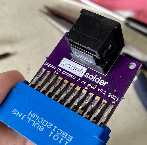
Still, with a couple big solder globs, everything reached. Resistance to noise? What’s that?
Testing
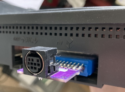
The adapter fit like a glove on the edge connector of the back of the Jaguar. I feel like if you’re going to make a proprietary connector on your computer or game system, then having an edge connector isn’t too bad of a way to do it. Just as long as you don’t use a weird, Sinclair-esque, pin count.
One of my Model 2 AV cables didn’t make a good fit, but it also doesn’t make a good fit into any of my Model 2s. The metal shield of the connector is just too thick, and is too tight to insert and remove without feeling like you’re causing damage. I ended up grabbing a different, cheaper-feeling Model 2 AV cable from my pile to test with.
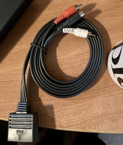
When I went to get the Jaguar out of the box it had been living in for the last couple of years, the first thing that fell out was this s-video cable! It must have gotten stuck in the bubble wrap, and I never noticed it before. I could have been enjoying s-video on this Jaguar the entire time!
Well, never mind that… let’s see if this adapter I just spent time and money on works. For my test TV, I picked my long-suffering Samsung 910MP. This flat panel has got it all: crappy composite quality, only one input, reduces fast motion to a blurry mess, and has a terrible upscaler, so it gets used for anything that might kill a TV. Say, sketchy homemade hardware that I didn’t even test with a multimeter first.
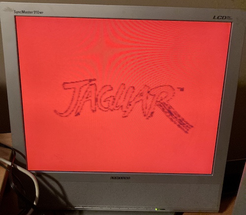
Oh no, the red screen of death! Don’t worry, the adapter is working: it’s still generating legible NTSC video! I knew from past experience that this screen was probably coming up because my cartridge was making a poor connection, a chronic Jaguar problem. I took the cart out, shook it a few times to dislodge any dust, and shoved it back in.
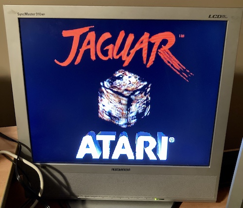
The Jaguar has booted! Notice the blurriness of the “cat cube” in the centre and the scaling artifacts around the “R” in “ATARI.”
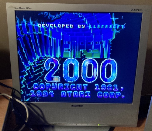
Did you think I’d test this console with any other game? Too bad I still haven’t figured out where my controllers went off to, but at least I know the Jaguar’s new AV adapter is working. I still can’t believe this worked on the first rev.
Conclusion
I’ve put the first version of the board up on GitHub with an MIT license. Please make your own boards if you need them!
While there are still lots of other places that this little mod board can go, I’m pretty happy with how it’s gone so far. It feels good to make a neglected console useful again, even though I wish I had noticed that s-video cable in the box ten years ago, back when the games and parts were much cheaper.
Update: RGB works!
Update: Blog superfriend Illuminado (seen previously with a ridiculously good-looking Game Boy Macro) has tested this board with an RGB-over-SCART cable made by Insurrection Industries. It appears to work just fine without the “wake up” line!
Looks very good indeed. Of course, this is highly dependent on the cable, and I haven’t scoped the sync coming out of the Jaguar to figure out if it’s TTL-level (like the Genesis) or something lower. Luckily, there’s plenty of room on the PCB to add voltage dividers and coupling caps to the design!