Make Your Own ColecoVision At Home (Part 3 - Joystick Fix)
Tags: console coleco colecovision leako homemade-hardware retrochallenge retrochallenge-october-2021 clone
In the last entry, I was left with a working ColecoVision-compatible board, albeit one with a very stuttery controller that would only work when connected to what I thought was the second controller port. Let’s fix that, and then enjoy the cheapo ColecoVision games that I spent all this effort building this thing for in the first place.
Any Port In A Storm
The biggest obvious problem is that I mixed up the controller ports. On the original ColecoVision, J5 is player two, while J6 is player one. I didn’t catch this until I realized that the buffers the controllers are plugged into are correctly numbered. This explains why the “player one” controls worked when I was plugged into the rightmost port, which I thought was player two.
However, this doesn’t really impact functionality. It just means that I put the port in the wrong place. An easy thing to fix with a new board, but not worth it until I fix the actual broken controller-reading function first. I made a mental note that the right port is “player one,” and moved on with life. No bug here!
Therapy For Mario’s Stutter
ColecoVision controllers are read in two “modes:” one to get the signals from the joystick and one fire button, and the other to get the signals from the number pad. The games instruct the Coleco to switch between the two modes and then read each half of the controller state independently. This was Coleco’s way of getting around the fact that the DE9 connector has fewer pins than the controller has buttons, without adding something expensive to the controllers such as an NES-style shift register, microcontroller, or a serial encoder.
Where to start? Checking over my previous work. If the sprite problem in the previous entry had been caused by sloppy soldering, it stands to reason that’s also the case here, as the same incompetent assembly person soldered that one too.
I looked at U23, which is the 74HCT00 responsible for running the “mode change” flip-flop, and noticed the solder on a few of the pins looked underfilled. If the pins are only making intermittent contact, it could cause unpredictable results. Since the IC is on the bottom of the board, gravity is going to fight us as well, increasing the chances of the pins lifting off the pads. I applied some flux and fresh solder and made sure that they were now affixed firmly.
A partial fix: now in Donkey Kong, Mario could run consistently and smoothly forever instead of the stuttery “drunk walk” he had before. I’m still not any good at the game, but that doesn’t matter. However, the keypad was broken now: pushing keys on the number pad no longer picked difficulty levels at the startup screen, nor did they move Mario around as they did in the previous entry. And games which used the two triggers for separate purposes (i.e. Cosmic Avenger) fired both at the same time when the left trigger was pulled.
So, something about the mode-changing state machine was still bad. Before sitting down to do any more diagnosis, I noticed a couple of underfilled joints on the I/O multiplexer 74LS138 chip, U13, as well. I went ahead and touched those joints up as well, flowing in a bit of fresh solder. This seemed to do the trick! Now I could start games with the numpad and play with the joystick, just like the designers had originally intended.
Because of all these bad joints, I’ve learned not to rush drag-soldering, and to double-check all of my work. I’ve also bought one of those el-cheapo LCD microscopes. The magnification on these is great, and it makes it very easy to see bad joints right away.
A Better(?) Joystick
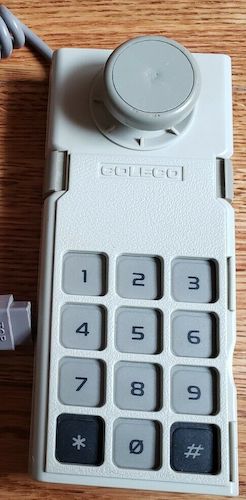
Back to the ColecoVision pad, then. Unfortunately, even after touching up the solder on U13 and U23, the up and down action on the joystick was still really rough. I felt like I had to push it much further for the up and down directions to register than I did for left and right.
Even though the console was working fine, this glitchy controller made a lot of games effectively unplayable, especially if they involved diagonals, which are already tricky on a properly-maintained ColecoVision controller. Clearly, my restoration of the Quebecois joystick in the previous entry was a failure.
I also tried with a previously-untested Wico Boss joystick that I got as part of a VIC-20 set – that project is coming soon. Since it’s Atari-standard pinout, it should work for the ColecoVision as well, as long as you have a number pad plugged into the other port to control the skill menu, etc. Unfortunately, the new-to-me Boss was extremely bad at pushing up or right, which meant that it went on the repair pile. Judging from a few threads on AtariAge, it seems like this model of joystick commonly needs a little bit of TLC.
A better-looking Coleco Adam joystick with cheap shipping popped up on eBay, so I leapt at it. The “grip disc” was missing from the stick on this one, too, and something had been chewing on it, but it seemed (from the pictures) like a tighter, better-treated unit that wasn’t missing chunks of plastic and a couple of its case screws. Besides, the grey Adam sticks are just cooler.
Unfortunately, it turns out that this controller was also bunk, and had clearly become rusted from sitting in some water. The “down” motion was great, but unfortunately the “up” motion was now nonexistent instead of really spotty. I’m assuming that “up” is the primary direction in which these controllers fail, either because of the leverage of the giant stick reefing on the thin leaf switches, or because of water ingress through the nearby cable hole.
After wasting a few minutes jigging up the connector in order to test the controller, I realized that the diode drop inside the controller would make the continuity test of my meter not work. My only way forward would be to take the controller apart and buzz it out from inside.
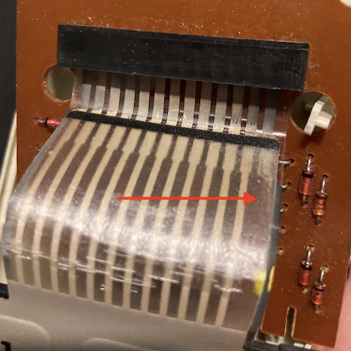
When I took it apart, I noticed that the ribbon was looking a little ugly going to the number pad, but it still seemed to work during my limited test. There’s not much I can do about that without pulling apart some stick-on parts, so I left it. After looking at it a little more, it seems like this particular trace is actually on the backside of the membrane, which is why it looks weird compared to the other ones.
I used a continuity test on the multimeter to test the leaf switches for the directionals, where I discovered the “up” switch didn’t register when I clicked the leaf. Additionally, all four leafs had very cold, very cracked solder joints with poor fill, a classic failure mode of these controllers. I sucked the solder out on all of those, and replaced it with fresh stuff.
On top of that, I assumed that the barely-plated leaf switches must have become oxidized, and tried to clean under them with deoxit and some alcohol scrubbing using a toothbrush. This seems to have worked, and all four directional leaf switches were now more responsive on the continuity test.
To top it all off, a number of the “crimps” on the edge had broken, so I again soldered them in. I did a little bit of cleanup of the shell to remove all the years of accumulated hand gunk, and then closed it up.
The initial test mostly cured the joystick, but neither of the fire or arm buttons worked. This made most games pretty unplayable, and I was getting tired of wondering if the problem was with the soldering on my board, the design of my board, some kind of board flexure issue from inserting cartridges, or the now nearly 40-year-old controllers of unknown provenance that I was jamming into it. I decided to go for the nuclear option.
When I first set out on this project, I considered building my own stick to go with the system, as the circuit is very simple, but the prices of Seimitsu and Sanwa joystick parts are a little steep, and by the time the planning looked like it would turn into a big project, I figured it would be better left for another day. That day has arrived.
Spend Fifty Dollars
Amazon has a bunch of cheap joystick parts. I seem to remember these kits being a lot cheaper in the past, but with the current shipping crisis, I don’t think I can really complain that much. Especially since the joystick housing must have been a mislisting, at nearly half the price I was seeing it sold for, even on AliExpress.
For what I paid for the housing, I think I got an okay deal, with some caveats regarding the quality control. They were clearly trying to drill this with very worn-out drill bits, as the holes in the case are fairly rough. The suction cups on the bottom go into holes that are less round than oval, and so I had to apply some old keychain rings (which I had on hand for some reason) to keep those suction cups from falling out of the bottom of the case. They also shortchanged me at least one nut, although I could easily have dropped that somewhere. Last, despite the cling-film protective wrapper, the shiny top is dinged up and scratched in a few places.
That last part is nothing that plastic polish couldn’t fix if I really cared, but if I were paying the full $59 that they were asking normally for this case, I’d be a little peeved. As for the buttons and stick themselves, they seemed fine except for the general cheap feeling of the ball top and scratches on all of the black buttons. The joystick also has a little bit of a long throw, which shouldn’t really dissuade anyone used to the ColecoVision. Overall, they work, so I’m happy.
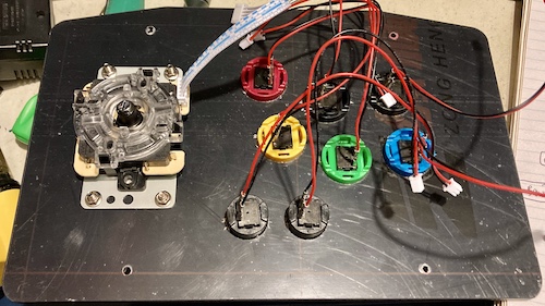
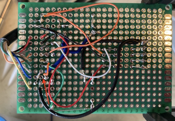
The parts kit I ordered is the usual one, containing a joystick, buttons, cables, and a “USB board” that has a potted microcontroller of some kind. I made a terrible protoboard out of a bunch of 0.1” headers – for each of the pre-crimped input cables – wired to a Sega Genesis extension cable that I had cut in half previously.
Board of Directionals
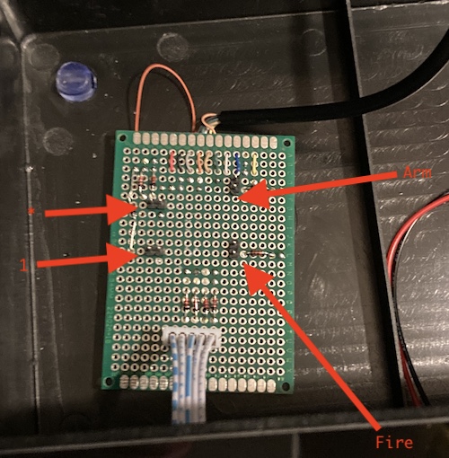
I had to do a little bit of work for the number pad - I wanted “1” and “*,” so I had to figure out where those were on the original matrix and transplant them into the new board along with their respective anti-ghosting diodes.
As briefly covered up above, the basic ColecoVision controller uses pin 5 on its connector as a ground pin for reading the number pad and one of the fire buttons, and pin 8 as a ground pin for reading the joystick and the other fire button. The number pad is sort of an abnormal interpretation of a keyboard matrix. Rather than “scanning” it like a real keyboard, which would likely waste a lot of CPU cycles, the buttons pull multiple pins to ground at once in a sort of bitflag structure – for instance, the “*” key pulls down pins 2 and 4 at the same time, and “8” pulls down pins 2, 3, and 4. That way, your game code can read the controller register in one shot, and index it into a simple jump table in order to respond to that button.
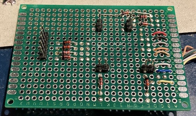
This was all done in a real hurry, in the true RetroChallenge spirit. I failed to reserve enough room for the 9-pin connector, and ended up kind of shoving it into the board wherever there was room, and running a jumper wire rather than desolder things to move them to a better place. As a result, my board looks like someone threw a bunch of multicoloured spaghetti at a protoboard and then melted a bunch of wiring insulation with a soldering iron over top of it.
Naturally, my first version seemed to absolutely not work, stalling on the “skill select” screen and not even allowing a regular controller plugged into port 2 to select that skill.
Don’t wire tired, because after a good night’s sleep I realized that I had accidentally bridged pin 5 (number pad select/ground) and pin 8 (directional select/ground) together.
Success
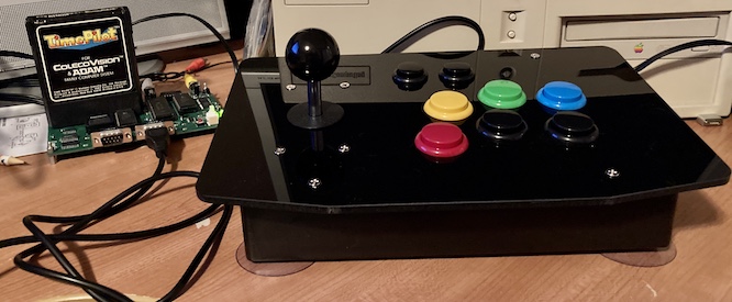
After cutting that bridge out, the joystick worked great. I was once again able to beat 1940 in Time Pilot1!
There are lots of leftover buttons on this controller, and I hate to waste them, so I hope to eventually either make this sort of a “multi-system” joystick (i.e. toggle between 6-button Sega and ColecoVision,) add more of the number pad, or integrate the Super Action Controller buttons. As it stands, most of the buttons do nothing and are just there to fill a hole in the case.
This could all get turned into a real PCB with more features. Maybe that will happen if there is interest down the line, but I strongly doubt there will be. Most people will probably be happier with this excellent open-source Coleco-in-NES-controller board.
Overall, I’m really happy with how this joystick turned out. While the circuit board is an absolute mess, this will provide a reliable testbed for other Leako boards (and possibly other clone machines down the line.) I definitely had a lot of fun plugging together all the big chunky joystick parts, too!
Next Steps
In the next entry, there will be more controller testing of the Leako. Coleco also sold trackball controllers (the Roller Controller) and steering-wheel controllers (you would think this would be named the Steering Controller, but no – it’s the Expansion Module #2) and support for them takes up a large section of the board. Will they work? Let’s find out together.
-
Stephen Cameron of the extremely comprehensive ColecoVision Addict website was kind enough to send me copies of Slither and Time Pilot with which to test the machine, and has been very encouraging throughout the entire project. Thanks Stephen! ↩