Mouse in the Artdink House (Travelling to Tokio, Part 3)
Tags: computer nec pc98 pc9801 pc9801ra2 homemade-hardware homemade-software mouse artdink
With the NEC PC-9801RA2, I’ve fought bad power supplies, battery corrosion, case rust, weird NEC design decisions, and flaky floppy drives. The only thing that’s keeping me from enjoying my quirky Japanese space-simulation game, Artdink’s Tokio, is the lack of a mouse. How can “just go buy a mouse” turn into an entire article? You’re about to find out.
Remember what the PC-9801RA2 looks like? It’s been a little while. Here it is:
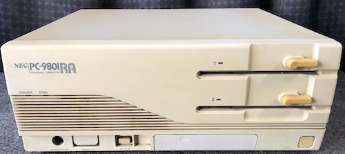
Perfection.
Mouse House
I do have a mouse for my PC-9821Ap2, but PC-98s also have two kinds of mouse connectors: the later mini-DIN (which I had) and the earlier DE9, which the PC-9801RA2 requires. It’s the same protocol, but on a different connector. And the passive adapters cost the same as or more than buying an entire mouse, especially after shipping.
To get a working DE9 mouse on this machine, I’d have to either buy a mouse, or build something.
PC-98 mice are not PS/2, USB, or PC-style serial – they’re a quadrature mouse, like those on an early Mac, Amiga, or Atari ST. The terminology in the PC community for this kind of mouse, inexplicably, is “Bus Mouse,” despite the fact that these mice are basically glorified joysticks, and only barely qualifies as a “bus” in my book.
I was hoping that this would be a situation of “just buy a mouse.” It wasn’t! Once again, I had an unexpected fight on my hands with this project.
Just Buy A Mouse
Thanks to a rare Buyee coupon, I was given ¥2000 to spend on anything I wanted at Mercari.
Surprisingly, it was hard to find a PC-98 D-sub mouse at all for twenty bucks, much less one that I actually liked, but I triumphed and located this very 90s-Art-Deco “Ellipstone” mouse by Elecom:
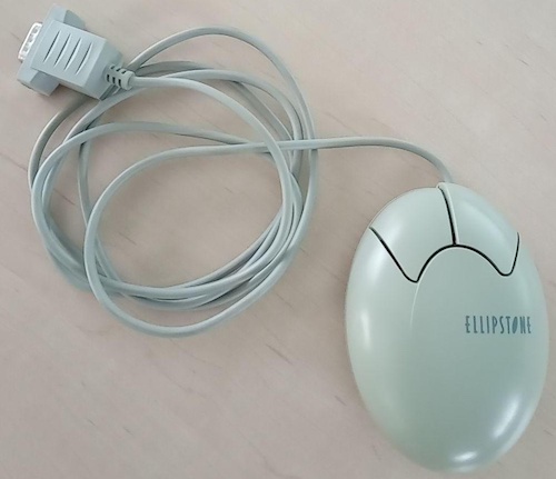
I really wanted one of the weird-looking Elecom Egg mice, but they were simply not available in D-sub at the time I was shopping1. This one is still very unique-looking, and a lot more fun to have around than the normal boring NEC “bar of soap” mice.
Mice are hard to get for any system, because nobody seems to want to go to the bother of listing them unless they’re really special. Their value is relatively low – I’m sure there’s lots clogging up Hard Offs all over the country, but only a very small percentage are making it to Mercari or auctions, and fewer still are being sold for anywhere close to what I’m willing to pay. It was a stroke of luck that I could get anything cheap at all.
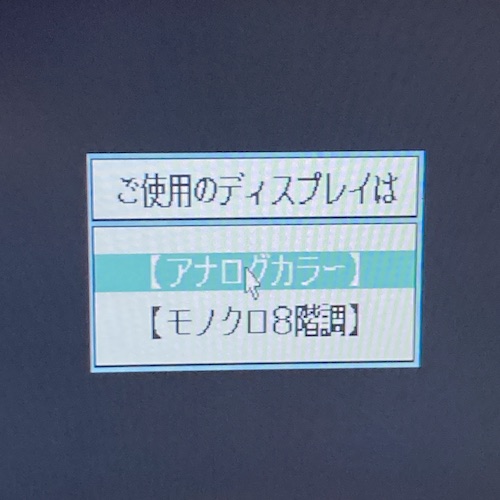
Unfortunately, when I went to test my pretty new-to-me input peripheral with my freshly cleaned PC-98, things didn’t work out. At the Tokio colour-mode-select screen, the mouse cursor didn’t seem to move. If I were to spin the mouse ball really, really fast, it would kind of quiver up and down by a few pixels, and that was it.
The mouse doesn’t work? You gotta be kidding me!
It was at this point that I took a couple days off, away from the PC-9801RA2. I wasn’t sure if the fault was inside the computer, or the mouse.
My Open Mouse Event Is This Weekend
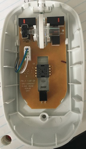
When I came back to it, I decided the best thing to do would be to pull the mouse apart. There’s one screw holding it together, under the “slider” sticker at the bottom of the mouse. Once the sticker is pried off and the screw removed, I can pull it apart at the top, where there are two clips.
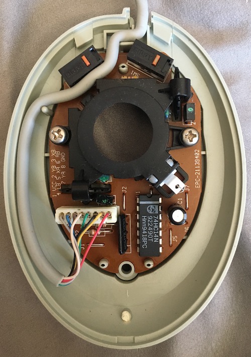
Inside the mouse is your normal quadrature setup, which I covered (far too briefly) in my article about testing the Coleco Roller Controller with my clone system.
This sort of mouse seems complicated at first, but it becomes simpler if you take it one step at a time:
- Moving the mouse ball turns a roller;
- That roller has a toothed wheel on the end that turns past an LED;
- A sensor on the other side of the wheel notices that the light coming from the LED seems to be “flickering” as the toothed wheel passes by it;
- By counting the flickers, we know if the mouse ball is turning, and how quickly.
- If we count the flickers in two places, we also know which direction the mouse ball is moving.
To use a real-world example, imagine running around a racetrack while two judges watch and yell as you pass2.
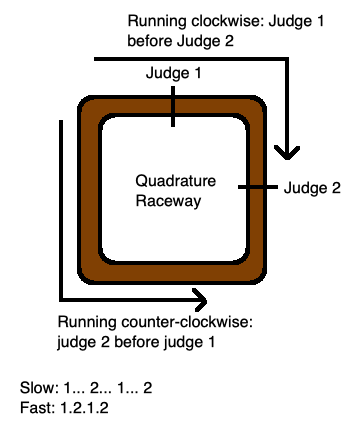
If you’re going clockwise, those judges will report that you crossed their respective lines in a different order. If you’re going fast, there will be a shorter time between the reports of those two judges. If you turn around and start running in the other direction midway down the track, you’ll pass Judge 1 twice in a row, in which case we’ll know that’s what happened. Those judges are positioned not 180 degrees off, too, because this way we can figure out which direction you’re going when you start from a dead stop – either you have to run the long way around or the short way around between the two judges.
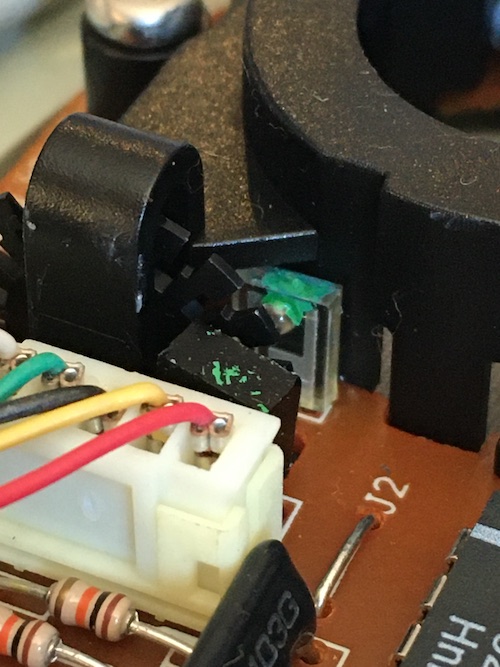
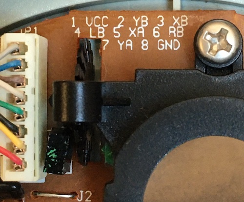
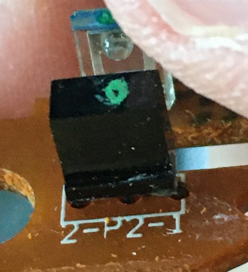
Electrically, these “judges” are a pair of photo-transistors – the clear boxy thing in the picture above – one for each axis, which pick up infrared light shone through a toothed wheel, and an amplifying IC (in this case a 74HC14 Schmitt trigger) that “cleans up” the analogue-y photo-transistor output into a digital square-wave signal that the computer will understand and interpret as motion.
Presumably, each photo-transistor contains two sensors, because each axis has to generate two signals – for instance XA and XB – which are used to figure out which direction the wheel is turning and how quickly. Sharp eyes will notice that the black emitter in the above picture is at a strange angle; I’m not sure, but I bet this is meant to make sure that it doesn’t catch any reflections. That may also be the purpose behind the strange green paint on the LED.
First, I buzzed out the cable. DE9 cables like this have very thin conductors inside them, and mice get dropped off tables or pinched under computers all the time. The continuity test showed that there was no breakage in the cable: even the “unused” pin 7 made it all the way to the PCB from the end of the cable.
I tried to back-power the mouse with a bench power supply, but I couldn’t figure out if the IR LEDs were lighting up. Since there’s an IR filter on my phone’s back camera, I had to use the front camera, which is not exactly easy to take photos with.
It didn’t make sense to me that both axes would be dead at once – I would expect that the mouse would be thrown in the bin as soon as one axis died, rather than the poor office worker continuing to use it “only vertically.” Other than the usual a-wizard-did-it theory of “ESD,” I didn’t have a good reason for explaining this failure.
I wouldn’t mind replacing these photo-transistors, but I couldn’t make out any part number or identifying mark on the parts whatsoever. Maybe these are jellybean parts, so generic that they don’t even bother giving me a part number, but I would assume that they’re tuned for the specific LED.
I scrubbed the phototransistors and IR LEDs with alcohol, and no obvious gunk seemed to come off. In fact, the inside of the mouse is practically immaculate, other than some crap on the rollers.
Mouse Inspector, Hand ‘Em Over
Without being able to see the LEDs, I wasn’t sure if the mouse was actually bad. So I rigged up a bit of a test environment, so that it could be hooked up to my oscilloscope.
I got a DE9 breakout set from Amazon (similar to the breakout that I used to build the Sharp X1turbo’s video cable) and hooked up power to it using a stripped USB cable.
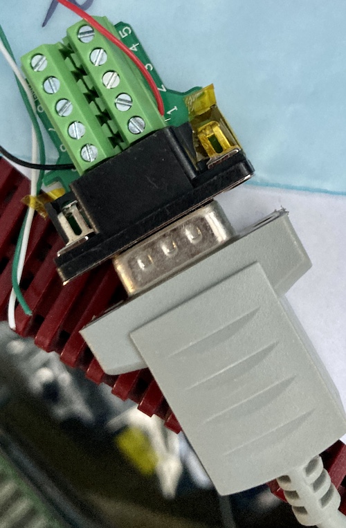
Then, I wiggled the mouse around while jabbing the probe into each screw terminal, in edge-trigger mode, looking for a change in signal that would indicate that that output is working properly.
Here’s the mouse’s pinout, and what I observed:
| Pin number | Signal | Works? |
|---|---|---|
| 1 | +5V | Yes |
| 2 | XA | No |
| 3 | XB | No |
| 4 | YA | Yes |
| 5 | YB | No |
| 6 | Left button | Yes |
| 7 | N/C | Mu. |
| 8 | Right button | Yes |
| 9 | GND | Yes |
That’s certainly consistent with what I was seeing on the computer itself, so at least we know the computer is okay.
So: my beautiful new PC-98 mouse kind of sucks. I should’ve ponied up the extra dosh and bought one of the brand new EGGs or CLAMs in the first place. Repairing it seems to be challenging, mostly because I don’t know how to source or even guess at the values of the replacement parts, but doable. Let’s shelve it for now, and figure out an alternative, because I am getting sick of having to fix things just to play this game.
To The Rescue
Coincidentally, at the exact same time this was happening, blog superfriend Edoardo in Japan was working on a PC-98 mouse adapter for another blog superfriend, Michelle. Of course, his went the other way – to the late-model mini-DIN – but he couldn’t resist the challenge of doing a DE-9 version as well when I asked him. And he even sent a couple of them to me! A prince among men.
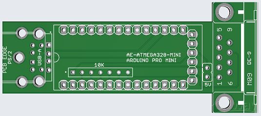
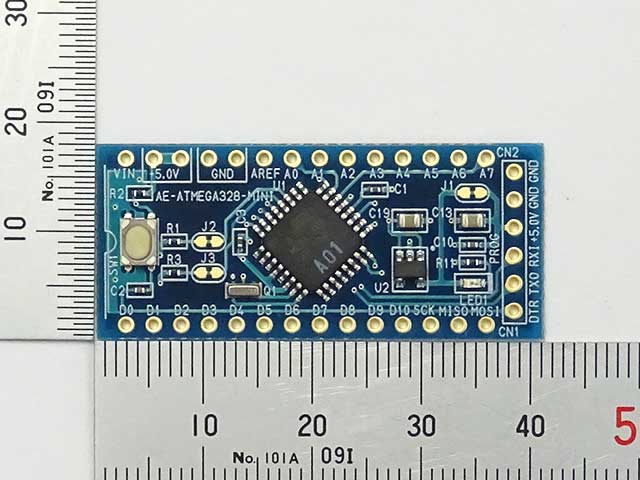
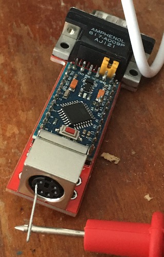
This first version didn’t work! Although we both agreed that it should use an Arduino Pro Mini as the brains of the operation, it turns out that there are a lot of Arduino Pro Minis out there. Specifically, he had targeted his board towards the one sold by Japanese hobby electronics chain Akizuki Denshi:
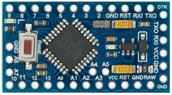
And I had bought a couple from AliExpress that look like this:
Lining them up, you can see that these two are just a little different:
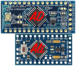
He was nice enough to redesign the board to accommodate my weird mutant one (which seems to be the same pinout and layout as the “official” Arduino Pro Mini board, so maybe AD is in the wrong here.) And I’m glad he did! I picked up the tab to order this one from JLCPCB.
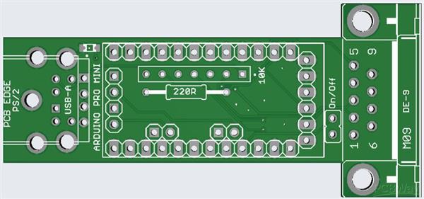
Assembly was kind of rough. There were tight spots, and I didn’t have all the parts, so I hacked things together, doing things like cutting up a 10kΩ resistor network because it had too many pins for the holes in the bottom. I was also in a rush, so I didn’t want to order the right parts. That’s the nature of building prototypes!
I decided to solder the Pro Mini directly to the board rather than use female headers, which cost more than the Pro Mini. This bit me in the butt later, and you’ll see why soon.
Not all the holes still lined up - a6 and a7 didn’t seem to line up properly in the rear, and there were holes for two other “side” pins that I didn’t have on my board. I decided not to populate a6 and a7.
The original version of the firmware was busmouse98, an open source project made by tyama501. Thank you very much for your hard work!
To program the firmware, I used an FTDI cable. Unfortunately, I couldn’t program the board properly, because I had done something very stupid. The programming header at the rear of the Pro Mini was soldered directly to the board. Usually, these stick upwards so they can be hit easily with the DuPont leads of the FTDI cable, but I wasn’t paying attention.
To make matters worse, the pinout on the board and the pinout of the Pro Mini disagreed! I was actually shorting some lines of the serial connection to +5V, which took me longer than I’d like to admit to figure out.
After I determined what I had done wrong, I desoldered the Pro Mini from the board, trimmed the six pins off, and then put some tape down so they wouldn’t short onto the PCB. I also went ahead and corrected/bodge-wired around some other errors in the board, where the board and the Pro Mini disagreed on which pins were VCC and which pins were signal. All of these bodges got incorporated into the final board.
Finally, after what appeared to be pure luck with a reset-and-DTR FTDI-cable-juggling dance, I was able to finally flash the board with the firmware.
This mouse-adapter board lets you use either a USB or a PS/2 port. You might not think USB and PS/2 are electrically identical, and you’d be right. Luckily for us, a lot of USB mice (probably nearly all?) will revert to speaking the PS/2 protocol if initialized as a PS/2 mouse.
All you have to do to make these mice into a PS/2 mouse is connect the USB D+ and D- data lines to the PS/2 data lines3. If you think back to when you first got a USB mouse and it came with that little green USB-to-PS/2 adapter, that’s all that adapter was doing – no logic involved.
I populated my test board with a PS/2 port because I didn’t have a USB-A port on hand, but it probably would have worked fine with one. Then I realized I could not find a PS/2 mouse in my home, so I ordered an optical PS/2 mouse from the jungle site for eleven dollars, next-day delivery, in the year 2023.

That’s two obsolete mice I’ve bought for this project, now.
This One Doesn’t Work Either
I connected the mouse to the adapter, and… it didn’t light up. Or seem to work.
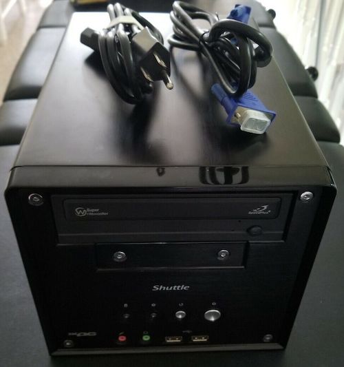
To check to make sure the new mouse actually worked, I dug out a PC with a PS/2 port. Despite what you may have assumed about the way in which I live my life, this is actually a bit of a project for me – I don’t have much obsolete IBM PC/Wintel hardware lying around. Eventually, I found a forgotten Vista-running, Shuttle-cased Athlon64 in a dark corner of the storage room, with one PS/2 port (marked “Keyboard” – we’ll see this fact again in a bit.)
The mouse didn’t work on that computer, either. It lit up as soon as it got power, even when the computer was off, but nothing happened when the computer was booted into Windows. So I went back to the storage pile, and pulled out the dual Pentium 3/1GHz machine running Windows XP that I used to use to make floppy disks.
Guess what? The mouse didn’t work there, either. So I took this brand-new mouse apart.
I didn’t see anything wrong with this mouse, except for a slightly-underfilled solder joint on the scroll wheel encoder’s ground. It didn’t make confident contact when I tested it with my multimeter, so I slobbered some fresh Kester solder in there and started the Pentium 3 machine again.
This time, the mouse worked great. I guess you can’t trust factories to make a reliable obsolete mouse these days.
Oh No, It’s Software, Too
Happy that I had somehow fixed this brand-new mouse, I set up the PC-98 setup again. When Tokio got to the “select a screen mode” dialogue box, however, the mouse still didn’t light up or work.
I went down the usual diagnostic procedure. Come, let’s climb the trouble tree together.
Does it have power?
I used my multimeter and saw +5.02V at a VCC pin on the Arduino, then opened the mouse, and confirmed that it was also present there. Yes, it has power.
Is it pulling too much current?
An optical mouse probably draws more current than a ball mouse because it has to make the shiny red light come out the bottom, right?
I doubted this very much, what with the brand-new Meanwell supply powering it, and a solid five volts on the multimeter. Plus, the datasheet for the optical-encoder chip onboard the mouse says that it only needs 10mA max.
Is it connected properly?
Maybe something was shorted to the PS/2 data bus pins, or the firmware was compiled with the wrong pin numbers? I couldn’t find any shorts, and I also made sure that the firmware was writing to the correct pins. Checking with the logic probe, stuff was happening on both the data pin and the clock pin, so the Arduino was communicating with the mouse.
Does the mouse need some kind of reset message?
Again, I saw this mouse light up without even turning the Shuttle-cased computer on. The code does send $f4 (enable data reporting) eventually, so I assumed it was fine.
Just to be sure, I dug up the datasheet for the chip inside the mouse. It is a glorious little part, called the PAW3515DB. This thing handles PS/2, it handles USB HID, it drives the LED, it does the camera encoding, fantastic.
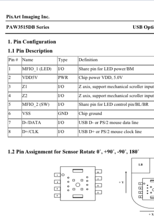
The only thing it doesn’t do is explicitly break out its internal quadrature signals4, which would make it so we wouldn’t even need this silly adapter.
I confirmed that data and clock were connected to the appropriate pins of this chip, which makes sense because the mouse was working just fine on the Pentium 3. At this point, I was reaching.
Does another mouse work?
Months prior, I had bought a cheap “arcade trackball” from eBay, intending to use it as the basis for a new Coleco Roller Controller clone, or an X68000 mouse. That hasn’t happened yet, but I did remember during the middle of all this mess that the arcade trackball uses a PS/2 interface (for building MAME cabinets, I assume) and went to go get it.
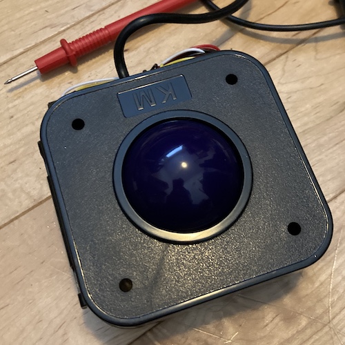
Did this mouse work? Yes it did! I didn’t have any buttons to click with, because the harness was a spade connector meant for arcade buttons, and I didn’t want to go hunting for my arcade parts bin in the middle of the night. I realized about an hour after I shut everything down that I could have just tapped them together for a click, but I decided I had enough for one day after successfully moving the mouse.
Inconclusive Conclusions
So what was wrong with the brand-new optical mouse? Nothing I could figure out from wiring – all the pins went to the right places on the Arduino, where the firmware expected them. Power was getting into the mouse, at the correct level. The mouse worked on another computer, and another mouse worked on this adapter.
There was a slightly frustrating explanation: it had to be a logical issue, in the firmware. This fancy optical mouse from the future must need some additional initialization code, or maybe the timing was off.
I consulted another PS/2 mouse library, the extravagantly good (and MIT-licensed) PS2-Mouse-Arduino, and started reading its setup code. It didn’t seem to be all that different, but it did wait for a little while longer before trying to send anything to the mouse, which made me feel like I was on the right track.
This made sense to me because I felt like a more complicated mouse would take longer to turn on. Its controller chip starts out doing all its little USB diagnostic stuff, realizes it’s not connected to a USB computer, and then eventually it gives up and drops down to dumb old PS/2 mode.
Still no light-up after copying that block of code. I then found this other project which claims to be a fork of the other one, but specifically with startup-code changes to help initialize PAW3515-based mice. It seemed like these changes were limited to trying to initialize the mouse over and over, and waiting quite a bit longer (500ms instead of 20ms) for cold start. Again, maybe this delay is enough for the PAW3515 to wake up and come alive. It used a slightly different strategy for writing to the mouse, too.
That modified code worked! I was at last able to drag my brand new optical PS/2 mouse around and see mouse movement signals in the serial debug display.
Hacking Isn’t Just For Furniture Anymore
I decided to try and graft this new PS/2 mouse code (whose mouse reading worked) onto the PC-98 adapter code (whose mouse writing worked.) There were some ups and downs.
At first, I started simple and just copied over the PS/2 send/receive code from the Mouse Handler library. It worked, but made the cursor fly off to the top right on its own, unless it was pulled hard to the bottom-left. This is because I didn’t read the PC-98 converter code closely enough.
The PS/2 library was trying to parse the entire datagram (multiple bytes, including position data) and then the PC-98 converter code was reading a few more bytes after that, and expecting those to be the position bytes, which had already been read (and discarded) by the PS/2 library. Even so, I was able to fight this bizarre gravitational pull to be able to click on the colour option with the new mouse.
That’s progress, although the mouse is certainly not usable while it keeps trying to fling itself into the corner of the screen unless fought off!
Pretty State Machine
The original developer of the PC-98 library had a super clever state machine for generating the quadrature signals. One switch statement handled both directions of signal generation, just by setting one bit in the “state machine position” variable. I’ve since borrowed this technique for other code.
However, I didn’t appreciate how clever this code was at the time, because it was after midnight and I was so close to getting the mouse to work, so I hacked it out. This is where I ran into a really nasty problem with modulo in C.
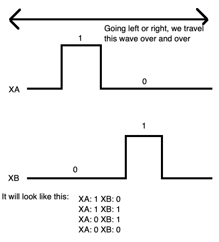
Let me explain by way of an example. We’ve covered quadrature encoding earlier in this post, and also before on this blog, but I’ll do a quick refresher. When you move the mouse left, the XA and XB signals on the mouse will pulse at different times (because the toothed wheel being rolled by the mouse ball will let the LEDs shine through and hit the sensor at different times.)
These XA and XB signals are basically “Judge 1” and “Judge 2” in our racetrack example from up above. Here is that example again, so you don’t have to scroll all the way up!
Since you have two of these sensors per axis, you can tell what direction the mouse is moving, and how quickly. For instance, if you have XA left of XB, and XA “sees” a hole before XB does, then you know that the mouse is moving left.
Computer mice didn’t invent this, as this sort of two-sensor system is the basis of basically all inexpensive relative-position encoders. Your car uses something similar to figure out the speed and position of the camshaft(s) (or the motor’s rotor, if you’re driving an EV) so it knows when to trigger injection/spark/etc events. Lots of factory equipment, such as CNCs, also use high-precision encoders that are based around this basic design. And so do arcade spinners, which you’ll be hearing more about in a future entry.
How does this affect me? Well, because I don’t have an actual “wheel” inside my adapter, I have to create an imaginary one and keep track of its position in software. I need to track a variable for the current position, and when the PS/2 mouse is moving left, I’ll decrease that position. When the PS/2 mouse is moving right, I’ll increase that position.
It looks sort of like this:
wave_positions = [
    XA on/XB off,
    XA on/XB on,
    XA off/XB on,
    XA off/XB off
]

if mouse dx < 0:
    wave_position = wave_position - 1
    if wave_position < 0:
        wave_position = 3
if mouse dx > 0:
    wave_position = wave_position + 1
    if wave_position > 3:
        wave_position = 0

emit(wave_positions[wave_position])
If you’re particularly handy with your C programming skills, you might notice the pattern near the bottom of that listing. Most programmers will use %, the modulo operator, to make a value “fit into” a box. So you could rewrite it to be something like this:
wave_position = (wave_position - 1) % 4;
// ...
wave_position = (wave_position + 1) % 4;
Modulo is not actually an operator meant specifically for this purpose. In fact, it’s the remainder of a division operation.
And this is where I went wrong. I dimly remembered that modulo on negative numbers in C didn’t work, and went to go check it out. However, I checked it out in the Python interpreter, because (being written in C) I assumed it would work the same way as C, and the Python REPL was faster to test with than writing a small C program.
Python did this:
>>> -1 % 4
3
Which is what I wanted, so I decided that C also behaved that way, and wrote the rest of the program.
Dear friend, it turns out that modulo for negative numbers in C does not work the same way that it works in Python. It works like this:
#include <stdio.h>
int main(int argc, char* argv[]) {
    printf("%i\n", (-1 % 3));
    return 0;
}
When you run that program:
% ./a.out
-1
That’s a very different result. As a result, whenever I moved left or up, the Arduino code would eventually reference position -1 of the state machine, which was unhandled, and fall through to the default case of “don’t move.”
Once I figured this little pitfall out, I patched the code to just use if-statements and wrap around, the explicit way.
Now the mouse adapter worked! It might be a little choppy on diagonals, but it seemed to be usable. More fine-tuning may well be needed. You can find the PS/2 to PC-98 mouse adapter code here, and get the Gerbers for Edoardo’s adapter board from PCBWay.
Finally, a working mouse! Since this project-inside-a-project-inside-a-project was now complete, I decided to go to bed.
Oh? Oh yeah, the game. That’s what this whole project was for, wasn’t it? Been so long, I forgot…
Dressing Up
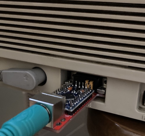
I decided to make the adapter look nice. It wouldn’t do to have an ugly-looking adapter, full of bodge wires and hacking and slashing, sticking out of the front of my machine as I take my first tentative steps onto the space station Tokio.
This is a very important thing to do, and not at all procrastinating just in case the floppy drives ended up not working again.
After measuring the board, I figured some heat shrink would work. I ordered some 30mm heat shrink for batteries, only to find out it was much less than 30mm. Then, I ordered some 40mm heat shrink for fishing rods. This fit, and looked really nice – it’s got a thick rubbery, grippy surface – except now it doesn’t fit into the hole in the front of the case for the mouse port.
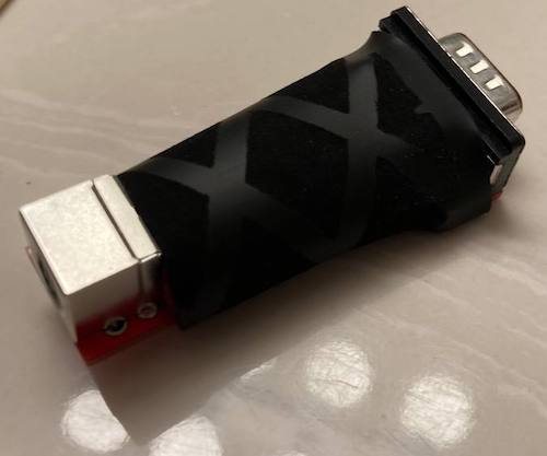
So I cut it off and then ordered another 40mm heat shrink from AliExpress, and here it is, a few weeks later:
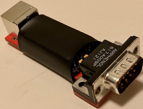
It still looks a little janky, but at least I’m a little less likely to short pins out now.
Playing the Game
At this point, I turned the PC-9801RA2 after it had been sitting for a few days, and it was no longer able to read the Tokio system disk without throwing an I/O error. Oh no! I was right back to the start of part 2!
After several weeks of cleaning and testing and despairing for awhile, I eventually realized that the drive would stay clean with repeated starts – if I stopped using the new JVC 2HD floppies that I had bought to write Tokio to.
Although I couldn’t see any evidence of it on the disk itself, every time I was using those brand-new disks, the heads would get contaminated with magnetic dust, something which wasn’t happening with my FujiFilm-branded DOS 3.3 and Columns disks, even after hours of use and multiple days of cold starts. Were the JVCs shedding from improper storage over the years since they were made?

To confirm, I ended up buying another set of FujiFilm 5.25” disks, something which is not getting any easier. These ones came in a fetching orangey-pink, to commemorate the 1990 World Cup.
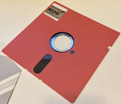
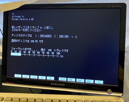
Just look at that gorgeous hub ring. These new diskettes formatted properly in both drives:
I was very disappointed, mostly because an entire box of increasingly-uncommon 5.25” high-density floppies now had to be considered untrustworthy. This ordeal did have a positive outcome, however. During my testing, I got so annoyed with the GBS-Control repeatedly dropping the video signal, that I went into the options and figured out that the problem was Active Frame-Time Lock. Disabling Active Frame-Time Lock helped my Samsung 931BW monitor lock onto, and stay locked onto, the signal coming out of the PC-98. I wish I had figured this out weeks ago.
I’ll devise an experiment to test these JVC disks later to see if any or all of them are actually bad, but for now, I wrote out another set of Tokio disks onto these new FujiFilm floppies, using the Greaseweazle, and prepared to test again.
On a cold start, after booting from the System disk, the game will ask me to insert the Data disk. After a long period of black screen and no disk churning, causing me to think the disks have gone bad and the game has frozen, it allowed me to pick analogue versus digital colour palettes. Once I picked that, we were back to the intro cinema.
![The game asks: you have been appointed as the 1st ward mayor of Tokio Ward. Please enter your name. Your name is: [Taro Tokio] (Is.)](/assets/tokio-naming-screen.jpg)
The game then asked me to insert the Game disk into drive B, which I did, and it asked me for my name. The default name is fine, so I clicked the です button and confirmed on the next dialogue.
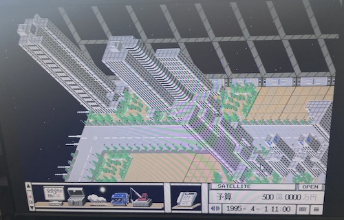
Voila: Tokio. There’s no in-game tutorial or even a reasonable amount of guidance as to what’s going on, which is sort of par for the course for Artdink games. You’re supposed to read the manual, and experiment.
The space station is already well-equipped with many skyscrapers, little single-family homes, and cars driving around, so I must be showing up quite a while into its operation. Boy, I’d like to drive a car on a space station someday. I guess anyone would.
There’s no sound or music yet, so I’m not sure if I simply have incompatible hardware or if I’m missing some configuration option.
Pushing the number pad lets me scroll around. It has to redraw the entire map whenever this happens, so progress is slow, even on my rip-roaring 386. I decided to fiddle around with the toolbar.
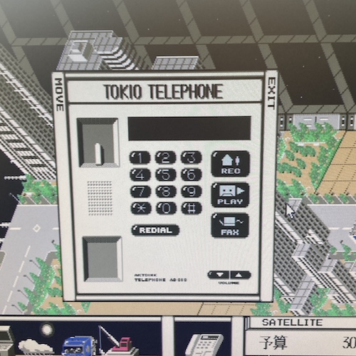
This button, which is always present regardless of what “floor” the toolbar is on, opens the phone. For some reason, you have the ability to record your phone calls, maybe so you can keep track of what your constituents want, or have an archive of blackmail material you can rely on to win re-election. Anything is possible in this game, because I haven’t read the manual.
I later noticed that in one of the options screens, you have the option to print out the phone listing for reference, if you have a printer attached to your PC-98. Surely that hard copy will be very useful when I’m lining up which crooked politicians to send faxes to on my futuristic space station.
Man, this really is a parody of Japanese government, isn’t it?
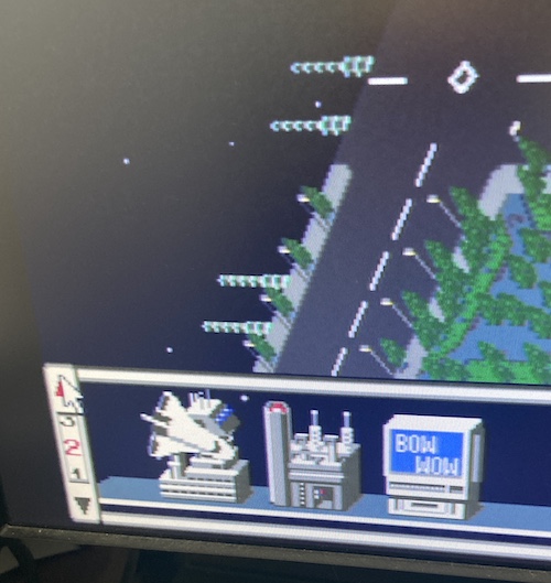
Like I said a few paragraphs ago, the toolbar scrolls with this little elevator-like “floor” selector. It scrolls very slowly. I know that the “space shuttle” icon on the left controls the space shuttle arrival/departure schedule to the station, and is therefore really important. But: I have absolutely no idea what “Bow Wow” is. Let’s click on it.
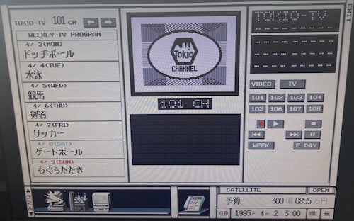
After clicking “Bow Wow5,” I realize that Tokio not only has an intricate city simulator, but also multiple television networks each with their own daily schedule! You can even record programs for later review.
In case you’re curious, the list of programs scheduled for Channel 101 for the week is as follows:
| Day (Weekday) | Program |
|---|---|
| 4/3 (Mon) | Dodgeball |
| 4/4 (Tue) | Swimming |
| 4/5 (Wed) | Horse racing |
| 4/6 (Thu) | Kendo |
| 4/7 (Fri) | Soccer |
| 4/8 (Sat) | Gate ball (never heard of it before: learn something new every day!) |
| 4/9 (Sun) | Whack-a-Mole |
Quite the diverse lineup of sports.
It looks like the VCR even has some kind of scheduler so you don’t miss the broadcast of these shows while you’re busy mayoring. Let’s watch one now.
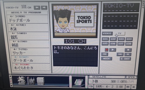
It’s a talking head, who says things faster than I can read (or even machine translate) them. I couldn’t figure out how to record or play this show again, so I think I will – again – have to read the manual.
Since it’s 4/2 in the game (see the lower right,) and therefore before the scheduled shows begin, I assume that this news segment (“Hello everyone in Tokio”) is general flavour text to introduce Tokio (the station) or some characters to the player.
Conclusion
So: Tokio works on my new 5.25” PC-98, and the goal has finally been achieved. This article has gone on long enough, so in the next part I’ll be covering my experiences with the game, ideally with a better-quality capture of the game images.
I promise to read the manual first, too.
You can get the components to build your own mouse adapter here:
| Component | Download link |
|---|---|
| Firmware | barbeque/busmouse98-byou |
| PCB | PC-9801 bus mouse adapter, Arduino Pro Mini version |
Bonus: Floppy Eject
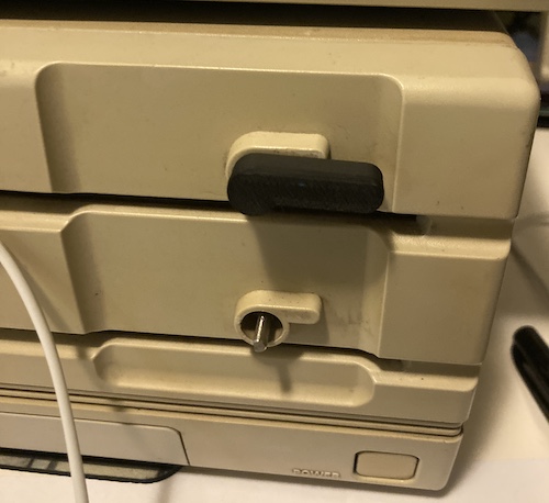
I finally figured out the magic combination of dimensions that made a 3D-printed floppy eject lever work out. Above is a picture of my, uh, seventh prototype, which certainly makes using the computer much more pleasant than using a pair of needlenose pliers to eject and insert floppies. Thanks to keegs for printing all of these for me.
For whatever reason, despite being printed to the same tolerance, one of the drives’ levers is ever so slightly loose on the shaft. It still works, but it will wobble a little bit during operation. Ah well… if it breaks I have a lot more!
Repair Summary
| Fault | Remedy | Caveats |
|---|---|---|
| Used Elecom PC98 mouse jiggles vertically, and doesn’t actually work. | I bought a broken mouse. | I’ll fix that mouse later, I guess. |
| New PS/2 mouse doesn’t work, even on a Windows PC. | Add solder to the ground pin on the scroll wheel encoder. | Still not sure if this actually did anything, but it works now on a Windows XP PC, and on the PC-98 adapter. |
| New PS/2 mouse didn’t work with the firmware. | Hack up the firmware until it does. | No idea what initialization signal/timing was missing. |
| JVC-made floppy disks didn’t boot, and then the floppy drive stopped reading disks after | Clean the drive and stop using those disks. | |
| I don’t know how to run a city | Maybe read the manual sometime? | It’s all in Japanese, though, and some of those words are big and scary |
-
I have since corrected this, but said mouse is in shipping hell. Thanks to Will.Broke.It on Discord for helping me find the mouse of my dreams. ↩
-
I know this is not really what judges do in real life, but maybe they are hungry dogs behind a fence and you have sausages strapped to your legs. Just go with it. ↩
-
This is absolutely not part of the USB HID standard, but I guess everyone figured it was OK to keep doing. ↩
-
That’s right, the mouse is encoding quadrature signals to PS/2, so we can decode them and synthesize quadrature signals again to tell the PC-98 the mouse has moved. Aren’t computers fun? ↩
-
Now that I know what it is, I realize that “Bow Wow” is probably a parody of Japan’s then-new subscription satellite service WOWOW, which is fun to say if nothing else. ↩