A PC-6001mkII keyboard replacement
Tags: computer nec pc6001mkii pc60 keyboard repair
My NEC PC-6001mkII has a very spotty keyboard. The captive-dome switches inside are too corroded or dirty to work properly, a common affliction of the model. Luckily, honet, a hobbyist in Japan, has produced a replacement PCB for the PC-6001mkII keyboard named P6KBPCB. I finally got my hands on one, and I’m going to install it.
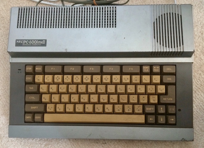
I’ve been looking for one of these keyboard PCBs for awhile. I even made a pilgrimage to Kaden no Ken, where they are stocked, to get one, but they were plumb out, having sold the last one the day before I flew into Tokyo.
Since they are only made in small batches, they sell out quickly, and it’s difficult to export them from Japan. But there is hope. Kaden no Ken has a “notify me when in stock” email feature. A few months after I got back to the land of salt and cold, they sent me an email saying I could swing by the store and pick one up. Sure thing, I’ll get right back on the plane.
Unfortunately for everybody, I’m not made of spontaneous plane trips to Japan. I told a proxy to grab one and send it to me via EMS. A few weeks later, it arrived in my mailbox.
What do we need?
As it was delivered, it’s just a bare PCB. There are no switches, no cables, and not even a power LED. What do we need to get to finish it off?
From the included instructions, you need:
- 73x Kailh “Choc” low-profile key switches. It’s recommended that the “STOP” and “Kana” keys have a different ‘feel’ than the others, in keeping with the original keyboard.
- The connectors, wiring harnesses and LEDs from the original PC-6001mkII keyboard.
- Some 1s1588 signal diodes, which are included in the package. Probably any other signal diode would also have worked.
I put off buying the switches, and then the price went up. As you can tell from the surrounding blog entries, I have no shortage of machines to fix, so the mkII sat and sat.
Sourcing parts
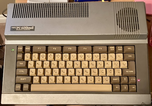
When I visited the Vintage Computer Festival Midwest in September 2024, I got to see a booth with a glorious thing: an NEC PC-6001mkII. Nephrite FM had been showing it off, and it already had this PCB mod done to it. After only a few seconds of typing in crappy BASIC programs, I was convinced that I had to get off my duff and finish the mod to my very own silver wonder.
After some searching to remember what box I put it in, I dug out this machine – along with some cables and parts that I had been looking for.
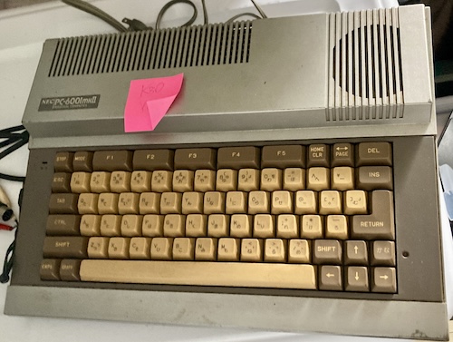
Because of the flaky keyboard, I’ve barely used this computer, and I feel guilty about it. I prefer to use the original model PC-6001s for most purposes, or the PC-6601SR if it’s something that needs 16-colour graphics.
Opening up the mkII to remove the old keyboard PCB gave me another chance to clean out the keyboard. It would have been nice to subject the keycaps to a Polident treatment to clean them up, but I’ve been warned against pulling key caps (their stems are very fragile.) So, in order to clean them and the top case, I gave it a thorough wash in the shower, then picked out whatever bits of nature I could reach from the edge. I also used an air compressor to blow out the grit, and then “flossed” between keys with a wet wipe. A shocking amount of brown gunk came out.
I would have used the CyberClean goop from the X68000 PRO episode, but all of mine has gone past the expiry date and I’ve noticed it has begun to lose adhesion. It shreds and leaves little bits of impossible-to-remove goop everywhere. This resulted in me having to fully dismantle and deep-clean a keyboard in the recent past, and I really don’t want to do this again.
Buying the switches (set of 110) from AliExpress cost me about $75 Canadian, or roughly 68 cents a switch. That’s a little pricey if you’re used to buying budget Gateron Cherry clones1 like I am, which are roughly a third the price, but Kailh stuff isn’t as popular. Amazon prices were just about double on everything, and only small quantities were available. Like on the VCF demo unit, I chose “brown” switches, which provide a good tactile feel.
I wanted to get blue “clicky” switches for the STOP and KANA keys. For some reason, though, I couldn’t find them in “V1,” only “V2.” Unfortunately, the footprint for “V2” seems to be incompatible with “V1” switches, so watch out. I’m sure you can still hack the board up to make them fit, but I wouldn’t want to take the chance on a relatively expensive board like this. I ended up putting in white clicky V1 switches instead, which I am happy with, but that inexplicably took a few weeks more to arrive.
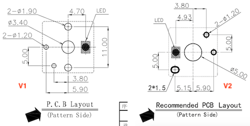
The V2 switches are a little pricier, too, at roughly 72 cents a switch. I still bought a small handful to sample for a later project.
The brown switches appeared after about a week, which is very fast shipping for AliExpress. I suspect at least part of the steep price on these switches is subsidizing this express delivery, which made me feel a little better about it.
Actually putting it together
The hardest part of assembling the PCB was actually figuring out where I had put it in my house. After digging through a few bins, I eventually found it stuffed into the bin that… holds the PC-6001mkII.
Past that, assembling any keyboard PCB is just monotonous labour. To paraphrase the immortal Mitch Hedburg, keyboards are great if you’re really bored and want to solder two thousand of something.
Because the Kailh Chocs fall slightly out of the PCB when it’s flipped over and sit crooked, I ended up using a piece of blue poster putty to hold each keyswitch in place while I did the initial solder joints. Then I’d push the switch with my finger from the underside to reflow the solder so that I was sure it was sitting flat.
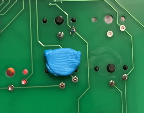
This still took a long time. Eventually, I realized I could just put the sticky tack on the plastic parts and use it to hold the switch’s plastic parts through the PCB. This made things go way faster, and I was quickly stuffing and soldering multiple keys at a time with the help of more dollar-store poster putty.
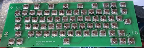
Some old parts need to be salvaged from the existing keyboard (which in my unit is an Alps 12KE 066A.) Desoldering the LEDs is a little tricky. Most of the instruction sheet, by volume, is dedicated to how you get the LEDs out and spaced properly so that they still look good on the new PCB. I do have replacement “square” LEDs on hand, in case this thing went really south, but I’d prefer to keep the old stuff.
It was here that I had a minor disaster: the PC-6001mkII’s original power LED had chunky legs, and with old solder stuck to them, they were simply too thick to go through the new PCB’s holes. I carefully hogged out the holes with a pin vise, but managed to lose the positive pad’s through-hole connection in the process by almost obliterating the topside pad. Only I could tear a pad on a brand new PCB.
To fix this, I scraped back the trace, tinned it, and then soldered a thin enameled magnet wire along that trace. Then I dropped it down the hole, and wound it around the leg of the LED. Soldering the LED in then secured the connection, and fixed the break in the pad. Checking continuity between that leg and the X-9 pin confirmed that it was re-established.
I did this to myself by rushing, but the PCB could be revised to make it less likely to happen. KiCad’s LED footprint expects a pretty skinny leg. A future revision of this PCB should try to have slightly larger through-holes for the salvaged parts, for situations like this. I know I’ll definitely try to use them in the future whenever I am making a PCB that expects the transfer of original parts.
For the red kana LED, I was much more careful about how I handled things. Primarily, I left myself enough time to actually do the job. That one snapped right into the new board and soldered in beautifully.
Wiring the matrix harness was a bit of a challenge. Not so much the desoldering or the soldering, but trying to manage so many same-coloured wires that were trying to jump all over the place. I did a lot of continuity testing.
At last, it was done. I screwed the keyboard PCB back into its plastic housing and dropped the entire assembly into the case. But would it work?
Did it work?
I fired up the PC-6001mkII, noting that the power cord was still sticky and had noxious green death poking out of the prongs, and was relieved to see that the keyboard was in perfect order.
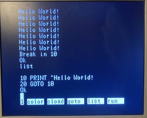
Every key worked! The kana LED worked! Unfortunately, the power LED did not. Had my clever bodge failed while I was installing the keyboard into the case?
No! My bodged pin of the LED was still rock solid, but now the other terminal no longer had a connection. I suspected that moving the LED around in order to fit it into the case finally broke the pad in that corner. If you don’t complete the circuit, the LED kind of doesn’t work. Little electronics tip there.
Clearly, I really should not have bored out those through-holes. Write that down, kids: don’t drill holes in brand-new PCBs because you’re too lazy to clean LED legs properly. To make matters worse, the whole thing was screwed together, so I’d have to dismantle the stack just to see the topside trace, so I could figure out which pin it’s supposed to go to.
Or, I could just go get the old PCB and buzz that one out. Seems much easier!
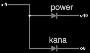
Through the magic of buzzing the old PCB out, I was able to figure out the LED configuration. Both LEDs are driven from pin X-9, and cathode-side switched via either X-10 (power) or X-8 (kana.) It’s that switched pin that was now missing on the power LED.
A quick bodge with some magnet wire and a tactically-applied drip of nail polish to pin it in place, and both sides of the LED were now connected. I had a moment of fear here where the keyboard didn’t seem to be responding, but it turns out that KANA + 5 (え) is not the same thing as actual “5” to the startup menu. Pushing the kana key again turned that mode off and I was able to enter into BASIC and do my typing test.
I noticed at this point that I was having trouble getting colour on the Samsung LCD over composite, so I switched to the MultiSync 3D. With the keyboard fixed, I can now finally write a short BASIC program to make sure I actually have “intense” colours coming out of the system.
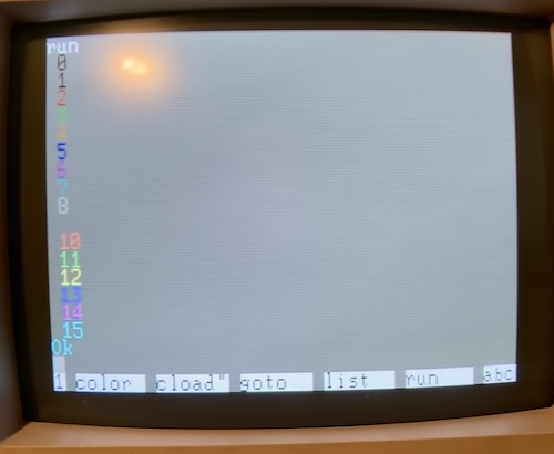
All 15 colours! Nice. The transplant has been successful.
I do need to figure out why this monitor shows a grey background (colour 9) in mode 5; it doesn’t do this on my PC-6601SR/Mr.PC. Something’s hinky.
Key-clusion
There’s still lots of stuff to fix on this machine: the shabby appearance, whatever is making the Samsung upset on composite, the mysterious grey background, some minor plastic repair, and testing to make sure the cartridge slot even works.
Update: It turns out the cause of the glitchy composite video was that the “mono/colour” switch on the back of the PC-6001mkII had rusted up a little. Moving it back and forth a few times produced solid (well, NTSC) composite video colour.
Even so, I’m very happy to finally have a working keyboard, so this computer can spend less time in the box and more time making weird smells. I should probably clean the power supply and motherboard, too…
-
Gateron does make a “low profile” switch which is roughly half the price of the Choc v1s. When I get around to doing the Tomy Pyuuta keyboard PCB I might use these ones. ↩