Let's say scram to SCART
Tags: arcade homemade-hardware supergun video
Back when I was putting together the Minigun supergun, my project progress was halted for months by lack of a cable. Of course, that Mega Drive 2 SCART cable did eventually arrive – the fourth one I ordered – but in the meantime, I got frustrated. And when I get frustrated, I tend to build PCBs.
Let’s eliminate the menace of SCART, and its additional connector, from the supergun “stack” with a quick-and-dirty modification to the open-source Minigun.
Refresher
Before we start, let’s go over the basics in case you haven’t seen the article from three years ago. What is a supergun?
A supergun is the community name for an adapter that lets you play arcade game PCBs at home. Put simply, it converts the video and audio standards that arcade boards use to work with a consumer monitor or TV, and it converts a common home joystick (usually a Neo-Geo one) to produce the signals that an arcade board expects. Of course, it also provides the common voltages to the arcade board so it can run at all.
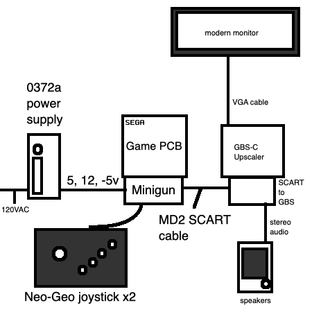
Previously, I had built an open-source “Minigun” supergun board. Most of the retro game community has a boatload of SCART stuff lying around, so it was configured to use a SCART cable for RGB video and audio output. In my case, I had to buy a new Sega Genesis SCART cable, which connected to a SCART-to-VGA adapter, which then connected to a GBS-C upscaler, and finally to the monitor I wanted to use to play games on. All of this stuff (and the GBS-C’s power supply) take up a lot of room on the desk, which makes it hard to find room for things like an oscilloscope, or even a game controller to play the games with.
I figured I could get rid of the SCART cable, and the SCART-to-VGA adapter, by simply putting a VGA port on the supergun board itself. As for the GBS-C upscaler, I wouldn’t need it because I had recently fixed up an NEC MultiSync 3D CRT monitor, which is capable of understanding the 15kHz video signals coming out of an arcade board all on its own.
PCB (Re)Design
The original Minigun files are indeed “open-source,” but not in the way that I expected. In KiCad, I am used to working with a schematic and a PCB layout. I make changes to the circuit in the schematic, and then apply those changes to the PCB layout, which is where I draw the traces and place the parts.
The Minigun zip file, on the other hand, contains only an EasyEDA PCB layout file, so after converting it to KiCad format using the wokwi web-app, I had to make all of my changes inside the PCB layout. Sometimes that meant dropping the PCB file into a text editor in order to add a net or two. Not my preferred way of working, but it got the job done.
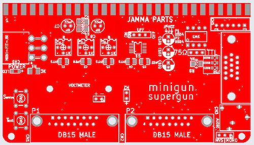
Since the VGA port is so much wider than a mini-DIN9 port, this meant that the board had to be extended a little bit. And that meant that some of the routing needed to be redone. And that meant that, after a few minutes of trying to weave new traces into the old, I told KiCad to delete all the existing routing, and just redid it myself, with questionable results for signal integrity.
The resulting board is somewhat of a dog’s breakfast, with mixed 1206- and 0805-sized SMD components, and through-hole 220µF capacitors right in the middle of the damn thing. But if it works…
Naturally, as soon as I sent away for this PCB, the universe shook one of the four SCART cables loose from shipping hell. That’s when the old Minigun project completed, and I happily enjoyed my games while I waited for the same shipping process to wend my new design to me. A little embarrassing, sure, but if there were no embarrassment, there’d be no blog.
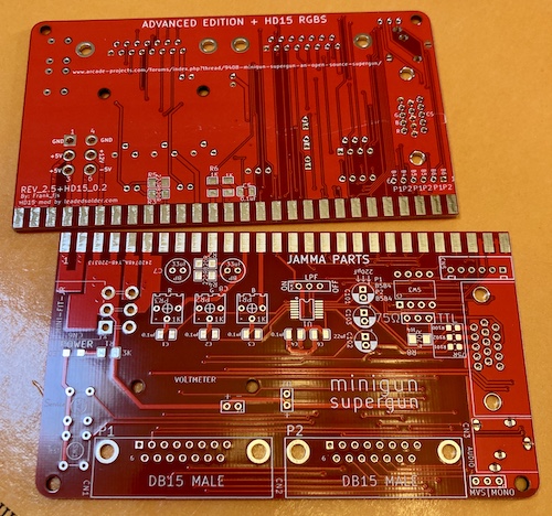
A few months later, I found these PCBs in a pile of other PCBs, and decided I might as well finish building them to see if I was right that it would be easier to play arcade boards without needing all these extra adapters hanging off the end.
Assembly
Last time, I wasn’t happy with how I soldered on the JAMMA connector. Because I didn’t bend the pins of the connector enough, the pins were hovering above the board and I was holding them on only with a copious glob of solder, which is not strong. Ideally, joints should be mechanically strong even before solder is applied. I’ve pre-bent connectors like these before on table edges, but the JAMMA connector has some plastic ribs on the backside keeping it from working.
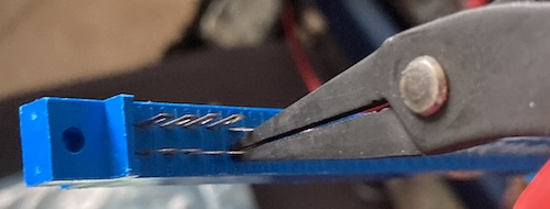
Instead of doing it the fast way, I used my trusty Hakko PN-2007 needlenose pliers to pre-bend the pins by hand. It felt like it took a long time, but it only took about a minute. Now, when I inserted the PCB, the pins all made good mechanical contact with the footprints.
I am sure in production they have some kind of fancy sheet metal brake that does this automatically, but at this tiny dirtbag-in-a-shed scale, it really didn’t take much effort.
To install the board into the connector, I wiggled it in from the side like doing up a zipper. This took a little while, but it demonstrated that the connector had really good grip on the board.
One annoyance is that the JAMMA connectors I’m using have obviously been desoldered from something else, probably a wiring harness for an adapter. Its pins are oxidized, the plastic is a little chowdered up, and some of them are crooked. This meant that I occasionally had to add a little bit of extra flux when I encountered a particularly gross pin that kept ruining my nice new solder. I was ready for this from last time, when I just gave it a huge glob of paste flux that made a mess of my workbench.
For a future revision of the board – if one ever has to be made – I think it would also be nice for the fingers on the board to be a bit longer. This way, I would have enough pad sticking out that I could be sure that I’m evenly heating both the connector’s pin and the board’s pad with the soldering iron. There were a few times when I ended up with clumpy or cold solder from the pin stealing all the heat, and even after a more careful reflow, I felt like the joint was not as good as it could be. We’ll see the consequences of that a bit later.
If there can be said to be a “worst” part of this build, it’s that, even after finding the baggie of parts from the previous supergun build, I wasn’t able to build it entirely from parts on hand. For instance, the kick harness is a JST XH 6-pin. I remember buying more than one of these for the previous supergun build, and it’s not like they’re particularly easy to lose, but it’s disappeared into the ether. I even have a box of assorted JST XH connectors, but they stop at 5-pin. In the end, I decided not to populate the kick harness connector, at least not until I got a board that needed it – my Sega ST-V is still sadly non-operational.
Unfortunately, I couldn’t run any boards without the 1kΩ colour-adjustment trim pots, which I know I have a bunch of somewhere. Luckily, none of these parts are actually expensive, but it pushed completion back a few more weeks while I waited for shipping.
I also ran into a real problem with the headphone jack – the footprint looked right, but more than half of the pins were turned in the wrong orientation. Huh?
Initially assuming that I had ordered the wrong part, I had to go back into the KiCad PCB file to figure out I had specified a $5.48 Switchcraft 35RAPC4BH3 – mostly because it was built into the EasyEDA footprint library, and which really should be the same as the headphone jack I ordered, because they look the exact same on the dimensional drawing.
When I looked at the KiCad editor, I realized that the EasyEDA-to-KiCad importer must have screwed up the footprint and I didn’t notice. The pad was in the right orientation, but the hole was not. I am surprised that this passed DRC! This would require a board re-spin to fix properly, so instead I decided to gently twist each pin 90 degrees using a pair of pliers, and then solder the whole mess down. That made the connector stick out of the board quite a bit, so I stuck some hot glue under it to serve as strain relief. Hey, it’s a prototype.
Fire it up
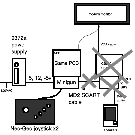
After some considerable re-organization of my test bench, I was able to get out the setup I had used with the previous supergun, which I have pictured here for the sake of comparison.
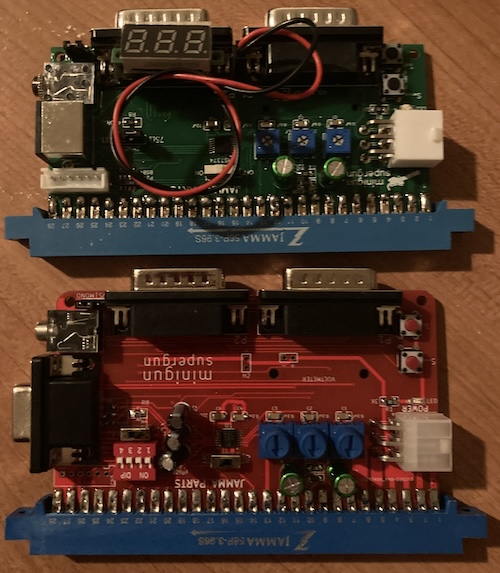
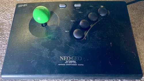
This setup consists of a cheap eBay power supply1 and a Neo-Geo controller. In the couple of years since the original entry, I’ve come up in the world, and now possess this heavily-battered Neo Geo 330 joystick to test with. No more CD controllers for me!
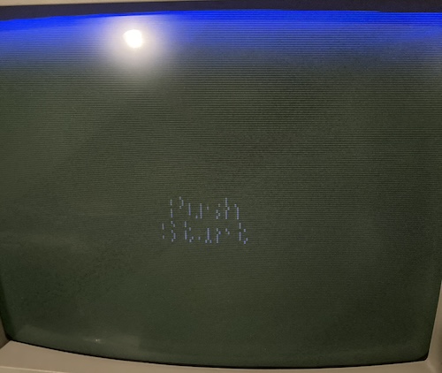
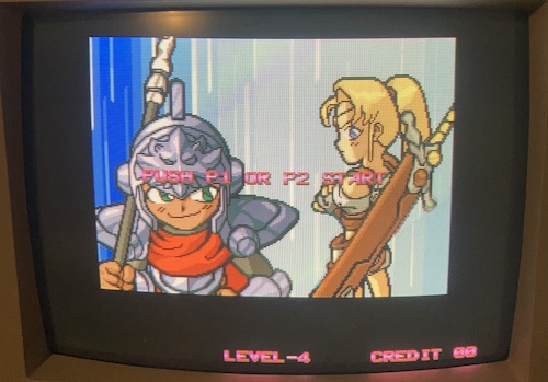
I plugged the new supergun into my trusty MultiSync 3D CRT directly, set the switches appropriately for a VGA source, and fired up Dottori-Kun. Dottori-Kun is a Sega test board for their cabinets, and it importantly is pretty cheap to replace if I accidentally miswired something and blew it up.
In this case, Dottori-Kun happily booted on the board, and showed “Press Start” on the MultiSync, but there was an ominous blue halo at the top of the screen, and the text was not visible no matter how much I twiddled the RGB attenuation knobs on the supergun board.
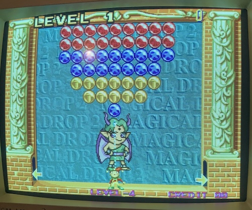
Dottori-Kun is a little weird with the video it generates, so I switched to something more normal: my Neo-Geo MV-1 board. This single-slot arcade board was loaded with what surely could not be a bootleg of Magical Drop 2. I fired it up and saw the Neo-Geo startup screen fill the raster.
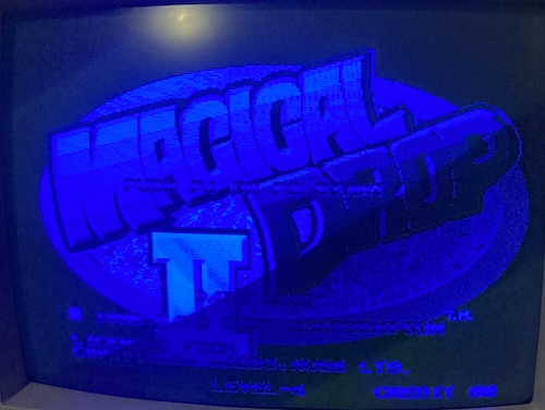
I Got The Blues
In blue, of course. As was the title screen. Adjusting green made the entire picture dim or bright, and adjusting blue seemed to blow out the contrast, but the red knob did nothing at all. I was very confused what was going on at this point.
Very nice and sharp, at least, and the supergun was working. But you could hardly call this configuration ideal. I wasn’t sure if this odd behaviour originated from the monitor misinterpreting the signal or the supergun being wired up wrong.
After opening KiCad and taking a really good look at the board, I realized that I had made at least one extremely dumb mistake. The order of VGA pins 1, 2, and 3 are red, green, blue… and I wired them up as red, blue, and green. That wouldn’t explain this exact phenomenon, but it certainly wouldn’t help.
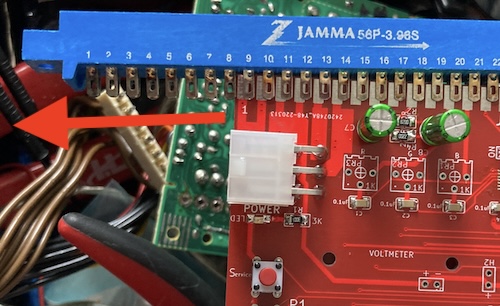
To make sure I was actually getting video, I grabbed the scope to work backward and figure out where the video stopped working. Red was not present at the VGA connector, nor at the output of the 7374… nor the input of the 7374. It was present at the JAMMA connector, though, and the only thing between there is a variable resistor and a bypass cap.
I switched the board off and ran a continuity test. Sure enough, the red (JAMMA pin 12) and blue (JAMMA pin 13) pins were not connecting to the trace right next to them. I reflowed them both, which made the joint look way better, and then re-checked continuity. Beep!
This is especially shameful after all the noise I had made up above about how nice my bent JAMMA pins work was. Next time, I will solder the JAMMA connector first, and also alter the footprint to have more pad meat so it’s easier to visually identify a cold joint.
The Bodge Tornado
Flipping blue and green was a bit of a challenge to do well. At no point on the board are the video signals able to be simply jumped without crossing over the board. Crossing sides with a bodge wire on this board is a big pain because every edge of the board has a port on it.
After thinking about it for awhile, I decided the best approach would be to remove these 75Ω resistors leading to the VGA port and rewire where they landed. Only problem is, they’re quite tiny.
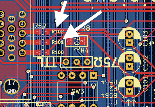
Initially, I was going to tombstone these and then run a wire from the top down to the bottom. But this was fraught with all kinds of fiddliness. jbevren suggested simply rotating them out so I’d have more room to run the wire. This was the right thing to do!
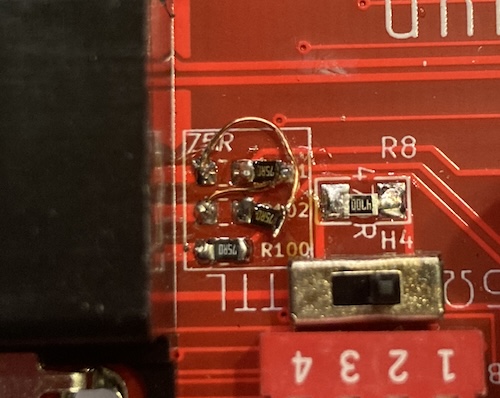
Just don’t look too closely at my soldering work. Phew.
Did it work?
![]()
I didn’t even have to adjust the pots to get this output. It looks really good!
At long last, CRT arcade goodness at home, without having to use my actual arcade cabinet. I am pretty lucky for a complete idiot.
Hooray!
Conclusion
This is a much easier supergun to work with, as now I’ve eliminated at least three of the components needed to make the original model function:
It still consumes virtually all of my desk to test, but at least now I also get to use my pretty NEC MultiSync CRT. And through testing the supergun itself, I’ve proven that it does indeed make the arcade board very accessible to the oscilloscope. What a great tool, that surely will not be used nearly exclusively for playing Sega arcade games.
Is there still room for improvement on the supergun? I think so. In particular, I’m curious if I could make one that converts RGB to composite video, using something like an AD724. I think that this would be a really funny project, with outcomes similar to Capcom’s infamous CPS-Changer of the 90s.
In keeping with the original license of the Minigun Supergun, this “HD15 Supergun,” with all the bodges mentioned in the article pre-applied, is available for download from the Leaded Solder GitHub repo. If you end up building one, I’d love to hear how it went!
-
I remembered during the course of this project just how much I hate this power supply. For some inexplicable reason (probably laziness,) I didn’t add a power switch to turn the whole mess on and off. Whenever I want to cycle the board, which happens a lot during testing, I have to pull the plug out of the wall. I’m gonna add a lightswitch box to this at the very least, I think. ↩