Moving Into a New Towns
Tags: computer fujitsu fm-towns repair pickups power-supply
There’s a lot of NEC computers on this blog, but tons of Japanese companies made great machines. Fujitsu, for instance, built a whole spectrum of computers. You’ve seen three of their 6809 machines in previous articles. Today, we’ll figure out how to get this sad 486-based FM Towns II to boot. Ideally, it should stay booted, too.
Introduction
What is the FM Towns? It would be easy to assume it’s a continuation from the 6809-based Fujitsu FM-8, Fujitsu FM-7, and Fujitsu FM-77… but not so!
Fujitsu made their own PC-incompatible x86 system to compete with the considerable might of the NEC PC-9801. One of the big ways in which it differentiated itself from its rival was the introduction of a mandatory CD-ROM drive. With this as a standard feature, they were able to position the Towns as a “multimedia” computer of the future, rather than the dour and serious image of Japan’s so-called national computer.
From what I can tell, its price was pretty close to that of the contemporary PC-98s (such as the PC-9801RA.) That would intuitively mean that Fujitsu was probably taking home a lot less profit than NEC1 after the cost of a CD-ROM drive, but I have no way of knowing for sure.

In a similar way to Apple of the period, there’s a great clash of aesthetics between 90s-stereo-futurism and the bright, cartoony vibes of some of the software.
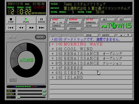

This particular FM-Towns II is an HR model, which means a 20MHz 486SX is riding along inside it. Its graphics chipset has hardware sprite support, unlike the PC-98 and IBM PC. All of the Towns machines also have a Yamaha YM2612 FM sound chip, so there’s a lot of potential for cool games and multimedia on the platform.
Tons of games were released for it, although the machine ultimately succumbed to NEC anyway, and the FM Towns became a boring PC-compatible at around the same time NEC gave up on the PC-98 as well.
Arrival
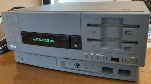
Isn’t it handsome? A lot of people think it’s less pretty than the FM Towns tower or the FM Towns II U-series all-in-one compact machines. All of the “grey” Towns machines look good in my opinion. I think the moulded-in floppy drive inserts and the glossy CD-ROM tray (with chunky eject button) give it a fun 90s-futurist personality.
This machine sparked a bit of a bidding war. It turned out to be fairly expensive, but still a decent deal compared to others I’ve seen.
The auction listing was from the original owner, and they reported that the power supply had failed to start after two years of storage. When it did work, video, sound, and CD-ROM were all tested as working, and the clock battery had been removed. Thank you for your diligence!
As I dug through the machine, everything seemed in order. Unfortunately, there was no expansion RAM in any of the slots, which means we’re stuck for now with the 4MB that is built in to the motherboard.
Power Supply Re-Cap
Anecdotally, power supplies seem to be a common Achilles’ heel of this computer. The towers and compacts are also bad for it. I hoped that I could quickly figure out what was wrong with the PSU and revive the computer. The last thing I needed was a couple weeks of waiting for parts in order to construct another new power supply, especially one for a thirsty 486.
That’s what we in the writing business call “foreshadowing.”
Getting into the machine is really simple, which is a big surprise after working with an FM77AV2, which could generously be described as “a huge pain in the ass.” Most of it is plastic clips, and once the back panel is removed, you can slide the power supply right out.
Immediately, I saw a potential culprit: a Nichicon PL 1000µF cap hanging out on the board. And because the PSU board is mounted upside down, it’s probably been dripping its corrosive death into the motherboard underneath. We’ve seen the damage that Nichicon PL capacitors can wreak on a board before.
I dismantled the PSU, the hardest part of which was popping the clip that held the pass-through power connector onto the thin steel of the case. At this point, I realized a bit of a pitfall: all the brown wires on the wiring harness are not the same voltage!
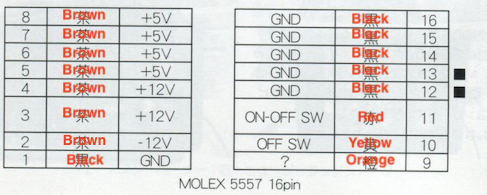
Indeed, checking the FM Towns Maintenance Manual V2.1, it seems like all the bulk outputs from the supply are the same colour. Talk about a trap for new players. The article goes on to describe how you can wire up an ATX power supply to replace the original Towns unit, but let’s not think about that for now.
Undaunted, I set about desoldering the caps. Each cap was tested on my Peak ESR70 ESR meter, in the hope that I would find a smoking gun as I had with the MultiSync 3D’s totally dead caps.
| Position | Capacitance | Voltage | ESR | ESR Good? | Comments |
|---|---|---|---|---|---|
| C52 | 1000µF | 25V | 0.04 | Yes (max 0.08) | Leaky |
| C53 | 10µF | 50V | 5.90 | No (max 1.60) | Leaky |
| C54 | 10µF | 50V | 1.22 | Yes (max 1.60) | Stinky |
| C57 | 2200µF | 10V | 0.05 | Yes (max 0.12) | Dry |
| C58 | 2200µF | 10V | 0.05 | Yes (max 0.12) | Stinky |
| C59 | 220µF | 50V | 0.07 | Yes (max 0.20) | Leaky |
| C60 | 220µF | 25V | 0.15 | Yes (max 0.25) | Too close to 78m15 |
| C62 | 10µF | 50V | 0.82 | Yes (max 1.60) | Very stinky |
| C66 | 2.2µF | 50V | “>40” | No (max 4.50) | Leaky |
| C69 | 10µF | 50V | 0.62 | Yes (max 1.60) | Dry |
There were a lot of badly-leaking caps on this board. The very first one I removed, the 1000µF, immediately filled the room with the stink of chemical death, but it tested out fine on the ESR meter. The 2.2µF is the star of the bad-caps show; I’m assuming from its small value that it serves some kickstart function that wasn’t happening.
As an aside, the FM Towns II compact machines also seem to have some pretty dramatic corrosion problems on the power supply board. In those, as here, we find the hated foe Nichicon PL.
I scraped away a bunch of corrosion near the output end of the PSU, and made sure there was still continuity. It seems like the only trace that was significantly affected was the one containing the 7912 linear voltage regulator responsible for producing the -12V rail. Then I tinned the traces and put on some nail polish for solder mask, which was probably a mistake, because of what happened next…
First, I plugged the system in with a AD-D15NE equivalent adapter so that my NEC MultiSync 3D could show the analogue-RGB output. When I went to turn on the computer, I was greeted with the FM Towns startup screen as it started to look for a boot disk. Nice!
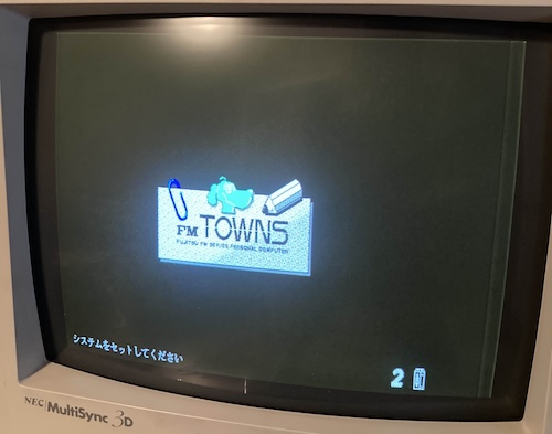
…and then I cycled the disc drive to check if there was a disc trapped inside, and the computer shut off immediately. Subsequent tests had the computer start up, run for a bit, and then panic and shut down. I didn’t hear, see, or feel the fan spinning, either.
I began to wonder if the CD-ROM drive might have been shorting or pulling too much current, causing the PSU to go into protection. The easiest way to be sure is to simply remove the offending components. I pulled off the front fascia of the computer (still just clips!) and then pulled out the CD-ROM and floppy drive. I think that this “sliding front bay” design must have inspired the NEC PC-9821Ap2’s fileslot. Thinking it could be clogged up and causing an overcurrent condition, I also unplugged the gross PSU fan at this point, even though it spun freely with my fingers.
Unfortunately, none of this made much of a difference. +5V also seemed quite low at standby, which was not a great omen.
I had a lot of trouble measuring the voltages during runtime, because the test hooks are at an awkward angle for the probes. Soon, the machine would just shut itself off as soon as I pushed the power button, which made testing virtually impossible.
I was going to have to go back into the power supply, and a good place to start was that very same corroded trace that I just sealed up with nail polish.
Power Supply Again
One of the first things I do when I’m studying a board is to look at the chips. Ideally, I’d like to have pinouts so I know what each pin does, but sometimes it helps to just know what the part is. The most obvious chip on the board is a PWM switch-mode power supply controller IC2.
There are lots of posts about the tower Towns II fingering the power supply controller IC as a cause of power supply failure, but this is a different part than that one. It’s not even the same manufacturer!
Another major IC on the board is an NEC chip marked “D4027BC.” Man, I’ve seen 40xxBC numbers before. Could this be the same thing as a CD 4027BC? A J-K flip flop would make a lot of sense to be used as a soft-power toggle switch – and a quick search confirmed it. So now we have an idea on how the on/off switch works.
Pulling out my transistor tester, I decided to check all the transistors in the area. If they’d been corroded, it wouldn’t surprise me if they had suffered some damage in the process. Testing them seemed to all check out. There were some really corroded solder joints near them, though…
After searching, I found this Japanese blog post about FM Towns IIHR power supply failure from July 2020 which fingers one of the resistors, R85, near the relay. I figured it would be worth checking out to see what was going on, and found that it appeared to be corroded.
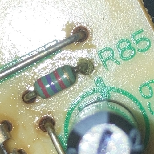
When I removed it from the board, its coating disintegrated from the heat alone, revealing big chunks of green death inside. It was measured out-of-circuit at 13kΩ, which I think is just a little wrong.
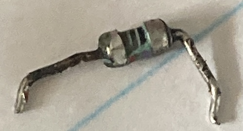
Thank you to Waiyama for posting about this. Nice car, by the way.
This resistor seems to interact with some kind of diode-based OR-gate and control access to the SET1 pin of the flip-flop. I was beginning to suspect that these sudden shutoffs may have been soft-power-related, not supply protection as I had first thought.
Using my cheapo jeweler’s loupe as a magnifier, I found a bunch of other greened-up resistors in the general area of the 1000µF PLs, which made sense to me, although none of them looked nearly as bad as R85 did. As the caps leak, their juices wick up into the legs of the resistors, which aren’t hermetically sealed against ingress.
A lot of the resistors were weird values, so I ended up doing a large order of resistors from Digi-Key that was surprisingly expensive.
First, I stuck in a replacement for the bad R85, leaving its body floating a bit out of the board so that I could easily grab its leg with the oscilloscope hook later, in case of further trouble. The Towns would start, run for a bit, and then shut off. No real difference.
I had a handful of other resistors that were out of spec, but not nearly as dramatically as R85 crumbling to bits as I pulled it – 25% off instead of the rated +/- 5%, for instance. This was one of those “put in the time” repairs, where I kept hoping for a smoking gun to explain the random shutoff.
Unfortunately, at this point I also started to have trouble reliably reading the resistors, and I knocked a couple off the desk when trying to desolder more than one at a time. The values were almost all unusual as well, which told me that those values must be important, and I’d have to place a big Digi-Key order to get more. Considering how this project was going already, I was starting to think of a plan B.
Supply Drop
As the work to save this PSU began to mount, I also started work on a contingency plan. After measuring the PCB, I started throwing together a very simplified version of the X68000 PRO PicoPSU board.
At first, I had thought that a PicoPSU wouldn’t cut it, and that I would need something beefier. That’s a tall order with a small, strangely-dimensioned power supply case such as this one. But after checking the sticker on the back of the Towns, I realized that I only needed about 60W in a stock configuration, and 120W maximum.
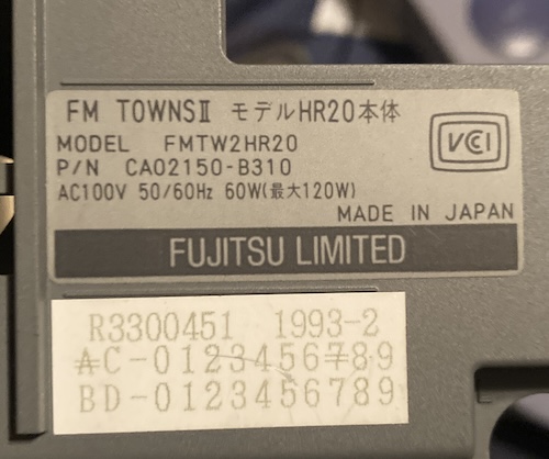
Since the previous owner did me the favour of also getting rid of a spinning-rust hard drive and its thirsty motors, I felt like I would be safe using a PicoPSU setup. Eventually, I do want to look at adding some expansion cards, such as the mysterious display cards, but that’s a long walk from here.
I chose a 150W PicoPSU-150-XT and paired it with a Meanwell EPP-150-123 to generate the PicoPSU’s required 12-volts from wall power. It’s not clear from the PicoPSU documentation just how much wattage for the +12V input is required to provide a given demand for system output, but I figured that I was not going to be running anywhere near the documented rail limits. Even 80% of 150W is all that the original power supply would be able to source, in either case.
Even with these relatively cheap commodity parts, the build cost of one of these supplies really adds up. The Meanwell was easily the most expensive part of this build, with prices no doubt climbing in anticipation of more tariffs. Hopefully I use this machine a lot…
At this wattage, a fan is mandated on the Meanwells, or they have to be derated. Without the fan blowing on the switching goodies, Meanwell claims you should only be pulling about 100W. Luckily for me, Fujitsu left a giant fan attached to the outside of the Towns’s PSU casing. It’ll help the PicoPSU, too.
I would have liked to use a single Meanwell module for all the output rails, but unfortunately they have very few units that use soft, or “remote” power on/off. And soft power is important, because…
Hard On-Off
This FM Towns, being a modernish computer, has soft power. Unlike the cruder machines in my possession, which are turned on and off by physically connecting or interrupting the flow of electricity from the wall through a chunk of copper, soft power systems become fully activated when triggered by a logic signal.
From the power supply’s perspective, it only has to supply a “standby” voltage (usually +5V, but there’s no particular reason for that if another voltage is more efficient) and some kind of logic to turn the supply “fully on” when requested. On ATX power supplies like the PicoPSU, this is implemented using an active-low pin called . Shorting it to ground – bringing it low, in other words – turns the remaining voltage rails on, and lifting it to +5V or letting it float will turn the power supply back off, shutting off the computer.
This has a lot of benefits, ranging from “don’t have to buy such a beefy power switch” to more sophisticated control of power rails. In the case of the FM Towns, you get a nice pleasant power toggle button on the front of the case, and software-controlled shutdown from inside the operating system.
Unfortunately, it meant that I had to figure out how to implement a circuit that would do the following things:
- When the system is off, pushing the ON/OFF toggle button turns it on.
- When the system is on, pushing the ON/OFF toggle button turns it off.
- When the signal goes low, the system should be turned off.
- Ideally, none of these things are glitchy or weird.
Requirements 1-3 were met with a simple flip-flop circuit. A flip-flop is a very common digital logic part that is, essentially, a 1-bit memory. You set it to on or off, and it keeps that information until you tell it otherwise. There’s many different kinds of flip-flop ICs out there, but the differences are usually down to what interface pins they expose (for example, offering a reset pin,) how many bits they remember, and how they are signalled (active high, active low, high-to-low transitions, etc.) Flip-flops are such a popular chip that I’m sure there’s lots of weirdo application-specific ones out there as well.
Because a toggle button needs to “remember” if the power is on or not (so it can then invert that signal,) I decided to implement it with a 74LS74 flip flop. Choosing this type of flip flop was determined by googling for “toggle button flip flop” and looking around for example circuits. It also helped that I had a bag full of these things and keep seeing them all over the place.
Remember requirement 4? Whenever you push a button, there’s no guarantee that the button is cleanly pushed at all. On a scope, “pushing a button” can often look noisy or wiggly, as the mechanical components of the button physically move around, momentarily breaking or making the connection. Interpreting this in a dumb way can make the button feel fiddly or glitchy. I’m sure you’ve had this happen in the past. Even if you’re really good at pushing buttons, you’re going to eventually “bounce” a switch. Filtering this phenomenon out is called debouncing.
I definitely didn’t want to have a glitchy power button, especially if that power button also toggled power on and off to the computer. When I hit that sucker, I want it to work. To make sure I did the best debouncing circuit I could, I then asked my buddy Scott about Schmitt triggers. A Schmitt trigger is a component that is meant to reduce noise and hysteresis, such as this button debounce. After I borrowed his napkin-doodled debounce circuit, and played around with a Digi-Key forum thread on the topic, I had a basic circuit for on/off and off that I was fairly sure would work.
To test that circuit before ordering a relatively expensive power supply board, I rebuilt it on a solderless breadboard. Remarkably, this worked the first time. Well, the first time after I fixed all the loose wires. Okay, the second time, after I realized that I forgot to power one of the ICs.
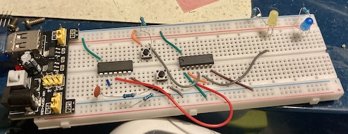
I then proudly shoved this circuit into the corner of the board where nobody would ever see it, in the hopes of optimizing the routing of the copper pours coming out of the PicoPSU.
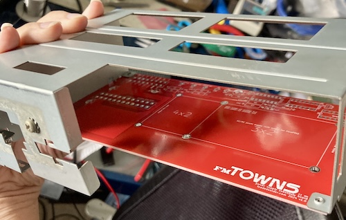
A couple weeks later, the new PSU board arrived. It looked great! As you would expect, I forgot to cut a hole for the middle mounting point on the case, but everything else lined up fine, even the little alignment tabs on the corners.
Unfortunately, the Meanwell didn’t fit. The cool footprint I had made awhile ago for the X68000 PRO PSU that is meant to fit both 4x2 and 3x2 Meanwell units doesn’t actually fit a 4x2 unit, because the “4x2” holes are 35mm apart from the “3x2” holes. In case you’re not great with the metric system, 35mm is somewhat more than “one inch.” That makes it more like a 4.37” x 2” footprint. Not ideal.
I ordered a replacement board, but as I was getting ready to chop up the old harness in preparation for its arrival, I realized I could probably just reuse the existing harness. It’s held into this cool plastic block, so there’s no way that I can screw up the pinout when assembling (designing is another matter.)
It didn’t have anything to do with the fact that I didn’t want to crimp up a new 16-pin Molex connector, trust me.
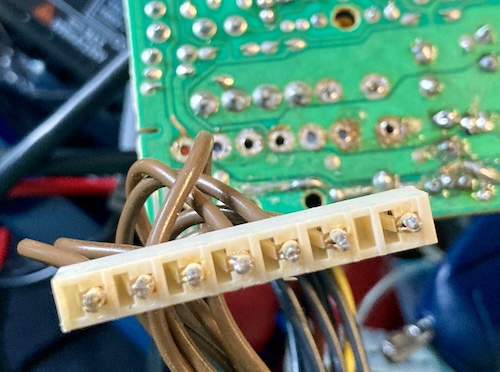
Not that desoldering the old harness was particularly easy, either. This connector uses those annoying spring clip pins that are really easy to assemble, but very difficult to reuse (because the spring clip ends up getting filled with solder during assembly.)
After some more tweaks and discovering other boneheaded mistakes like this, I ordered a third replacement board. Yep, I’m sure saving money doing it this way.
I was fairly confident that this spin would go well, so I ordered a larger diameter tip for the ol’ Hakko FR-301, settling on the 1mm x 4mm tip. I was hoping that the larger hole in the tip would make it easier to desolder these spring pins. Unfortunately, the tip didn’t really help that much, although it definitely did a great job of melting the insulation on some of the thin signal wires. Oops.
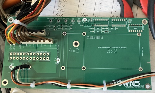
In the end, I had transferred the entire harness to the new board. I now regret not buying a pre-made 16-pin Molex harness from somewhere and using that instead, especially now that I’ve discovered the part on Digi-Key where they sell brand-new wire-to-board crimp pins. All this is for entertainment value and not instruction, folks.
I installed a 20-pin ATX connector into the 24-pin ATX footprint. They are backwards and forwards compatible with 24-pin ATX footprints, so I always try to put down a 24-pin on my board designs if I can. To top off the assembly, I installed the Meanwell into the board using a stack of #4-40 standoffs and nuts, which I applied blue Loctite to in order to make sure they don’t accidentally come loose from the vibration of the fan and/or moving the machine in and out of storage.
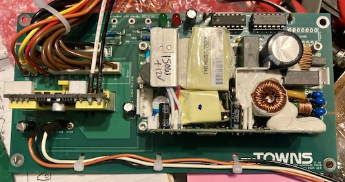
Wow, that’s a beautiful board. Because of my historically poor measurement skills, I did make a few components a little too close to the Meanwell for my comfort, but they aren’t electrically or thermally interfering, and there’s lots of airflow for the Meanwell.
The actual power supply part
Now that I could put the PicoPSU and the Meanwell onto the board, the next step was to start crimping harnesses. I needed two harnesses: one to carry power from the wall into the Meanwell, and one to carry +12V from the Meanwell into the PicoPSU.
Crimping up the +12V is relatively easy. As I have done on many previous supplies, I cut the barrel jack off the end of the PicoPSU and crimped the pins for JST “VH” connectors, sticking them into a 4-pin 3.96mm housing.
I really wanted to get rid of the hard-wired power cord. As many long-time readers know, I hate having power cords dangling out the back of my computers. They get in the way when storing, they dangle precariously while trying to fish them through the desk, and they’re generally annoying. This Towns power supply originally had a “pass through” connector right next to the hard-wired cord. It’s meant to provide power to a monitor or other peripheral through a regular wall-power socket, so surely I can just pop out the pass-through output, and put my own connector on there to serve as a power input instead.
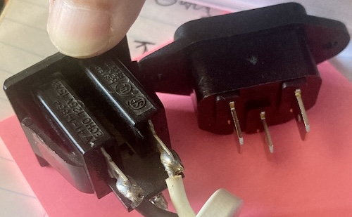
Unfortunately, the IEC C13/C14 power connector is a lot wider than the “pass through” power connector is – almost 10mm wider, in fact. The cutout in the case was not going to fit it. I considered cutting the case to make room for it, but in the end I decided I would just run a hardwired power cord out the back and dummy out the pass-through connector entirely.
I ordered some Monoprice power cords to cut up, but through some kind of idiocy on my part, I ordered a whole bunch of useless ones that were only 1.5 feet long. Monoprice takes over two months to ship to my house, so I decided it was best to not make another order of the correct length. This project has dragged on long enough. Instead, I dug through my pile and found another Apple charger extension cord, the same kind I used previously on the X68000 power supply.
For some reason, this Apple cord used the European wiring colours inside - brown for live, blue for neutral – despite being purchased in Canada and clearly meant for a 3-prong 120-volt North American outlet. Go figure. I cut the end off of it, threaded it through a strain-relief grommet, and did an underwriter’s knot, before crimping it for JST VH and connecting it to the Meanwell part of the new supply.
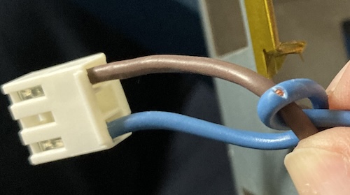
I then found out that at some point – probably stripping the wire, or rubbing it up against the razor sharp power supply housing - I had cut into the neutral wire. That’s not good. I cut it back, stripped again, and re-crimped. Then I just had to look for the screws I misplaced when I started this project several months ago…
Putting it into the Towns
Initially, I wanted to test the power on/off logic separately. That would require soldering a tac switch to the underside of the board and running it on my bench, which I didn’t really want to do. So, after waiting several months, I decided to just shove the power supply in the Towns.
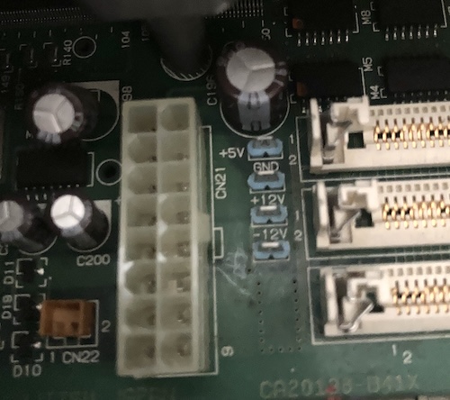
My first order of business was to consult the voltage test points on the Towns motherboard. They’re pretty well-labelled, and easy to hit with test probes, which is to Fujitsu’s credit. I always start with a basic sanity check: are any of the voltages shorted to ground, or each other?
That test came up negative, which both proved that there were no shorts on the power supply board, and also that I hadn’t mixed up part of a voltage rail. Then I used the points on the underside of the ATX connector (I really should have labelled this – fixed in the repo) to do a continuity test to make sure they ended up in the right place. +5V, +12V, and -12V all connected where I wanted them to.
Now, reasonably confident that I hadn’t completely hosed things, I installed the power supply into the case, routed the various cables, and got ready for a test.
Let’s Go Into Towns
For my first test, I made sure to clear a lot of desk space, and set the Towns up on its own power bar. That way, I could flip the switch off (or pull the cord) if things got bad in a hurry. I also made sure I had a fire extinguisher close to hand. Even after building so many freakin’ power supply projects, I still get antsy about that first loaded-up run.
My first surprise was that the power supply turned itself on as soon as I plugged it in. Whoops. I must have screwed something up in the soft power. That said, the supply came on properly, and the computer lit up the monitor and started drawing the Towns boot screen… and kept running.
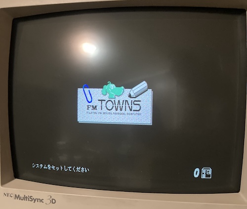
I started my stopwatch, and at 15 minutes of continuous runtime, I decided that the power supply replacement was probably successful. The CD-ROM tray opened and closed when I pushed the button, and I was pretty sure I also heard the spindle motor rev up too. Although the dirty system fan is running and pushing a lot of air, its bearing sounds pretty noisy, so I may need to oil it or budget for a new one.
After the 15 minutes, I went ahead and tested out the power button again. Pushing it turned the computer off, nicely. Pushing it again turned the computer on, nicely. In other words, the power supply hit most of my goals.
My next move on the Towns, after convincing myself the power supply worked “well enough,” was also straightforward. I wanted to boot this computer into actual software. In my voluminous hoard lives an A-Train III CD-ROM for FM Towns.

Hey, it works!
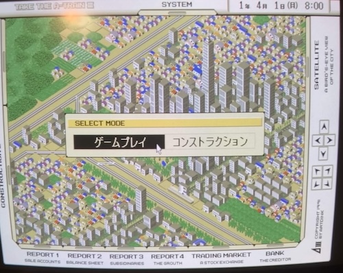
I can’t wait to be able to click these buttons.
What’s next?
Obviously, the next step is to figure out why the supply turns itself on when it’s introduced to power. I’m hoping that I just screwed something simple up on the reset circuit, and I can quickly modify it without needing a re-spin (and corresponding labour-intensive rebuild.) Once that’s figured out, I will open up the GitHub repository for the board. If you are OK with the current status of the board and need it to resurrect your own FM Towns IIHR, please let me know privately and I will mail you a spare board to build up.
Personally, I never leave my old computers plugged in when I’m not using them, so this will probably be just fine for my needs until I can figure out how to fix the bug.
Now I know the thing boots, so another good project on this computer is to either get a keyboard and mouse combo, or build some kind of adapter. Thanks to the hard work of other folks, I’ve already secured a Hirose HR12 connector to build a keyboard adapter. The protocol and pinout for the keyboard and mouse are well documented in the official Fujitsu FM Towns Data Book, which I look forward to reading cover to cover.
There is still one feature left to test on the power supply: soft-off. That will require me to get into an operating system that has a “shut down” option, and then pick that option. Imagine how much more stuff has to go right before I can truly test this one little signal on the PSU board!
Last, I want to build a SCSI adapter for the weirdo connector inside the system, and then install a BlueSCSI or some other SCSI emulator, so that I can boot my Towns without having to worry about CD-ROM drives ever again. After that, I’ll be browsing the huge piles of FM Towns shareware that Fujitsu has compiled on various CDs, and generally enjoying my life in a new Towns.
Thanks for reading!
Where to get it for yourself
If you want to build your own, I have open-sourced the FM Towns IIHR power supply project on my GitHub account. Gerbers are provided for download in the Releases section, but the BOM and installation instructions are a work in progress.
Repair Summary
| Fault | Remedy | Caveats |
|---|---|---|
| Power supply does not stay on. | Inspect and replace R85 resistor, clean corrosive capacitor leakage. | Other resistors are also damaged. |
| Power supply still does not stay on. | Replace entire power supply. | The prototype supply does not stay off when you plug it in. |
-
Like Apple during the post-SE era, Fujitsu did not include a keyboard with the Towns system, with the claimed aim that buyers could choose which one they wanted (including several with OASYS-like key layouts.) Maybe this was part of a scheme to reclaim at least some of that margin. ↩
-
For those of you following along at home, the switch-mode IC appears to be an NEC µPC1099CX. ↩
-
A cheaper option is the 120-watt EPP-120S-12, but at the time of development it was only $3 less, so I figured I would rather pay the three bucks. When I designed it, we had at least one fewer war than we do now. The price of the 150-watt unit has crept up, and as I’m editing this, it’s now $12 more than the 120W. ↩