Call In The PROs When You Need Power (X68000 PRO Part 2)
Tags: computer sharp x68000 x68000-pro repair homemade-hardware power-supply
Now that I had a reasonably clean X68000 PRO to work from, I set about restoring power. Rather than doing things the cheap way and strapping up my Meanwell four-voltage test supply, I decided to go whole hog and lay out a brand-new power supply PCB.
Why?
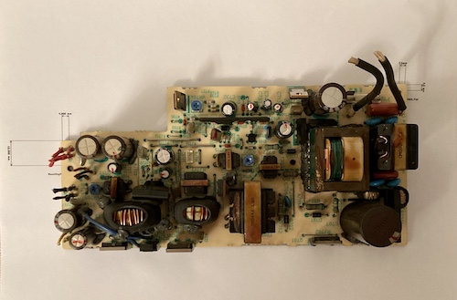
Previously in this series, I found that the original 100V X68000 PRO power supply would need a lot of work to bring it back to life. On top of that, even once it was repaired, it would be difficult to trust. On top of that, Canada does not offer Japanese 100VAC wall outlets. If I was going to put in all the work needed to rebuild a power supply, I want it to work on good ol’ 110.
The Design Begins
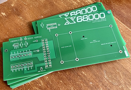
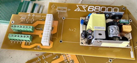
I was most nervous about replicating the weird outline and mounting holes of the original PCB, but I got it right on my first try:
The design I did was basically a clone of the excellent mattsoft one that I put into my X68000 ACE. In case you missed it, that board feeds wall power into a 12V DC power supply, which powers a PicoPSU, which then feeds the computer’s various power rails using the original wiring harness.
This design worked great for the ACE, and I had even more room to work with inside the PRO PSU case, so I made some changes. For starters, I left optional room for a 4”x2” AC-DC converter, instead of just the 3”x2”. I’m not sure if this is some kind of medical-equipment standard or not, but this kind of integrated AC-DC converter seems to hew to one of these two sizes, with the four-inch variety sometimes being cheaper (and probably easier to cool.)
One obvious downside with this design is that when the X68000 is “off,” the converter will still be running, generating heat, and consuming a considerable amount of electricity just to power the PicoPSU’s +5V standby rail. This isn’t a problem on the ACE, which has a hard power switch for cutting off the wall supply, but the PRO for whatever reason does not. I might add a switch like this later, but for now I’ll just have to remember to unplug it when it’s not in use for a long period of time – which is probably a good thing to do with any old computer, especially ones with homemade power supplies.
Keeping in mind the shortages at the time, I also specified a 24-pin ATX connector instead of 20-pin, as the 20-pin connector was backordered for several months! You can put a 20-pin connector onto a 24-pin footprint, but it’s not so easy to do it the other way around. In a similar vein, I chose a 3-pin header for fan power, so that a modern Noctua fan could plug in without modification or long adapter wires. A 2-pin header could always be substituted in order to use the original fan.
For the +12V offline supply, I picked a Meanwell EPS-65S-12, which is a 3”x2” 65W 12V power supply that cost about twenty bucks and accepts anywhere from 80VAC to 264VAC as input. It’s Class II, or double-insulated, so it doesn’t need to be attached to the frame ground (and thus the ground prong of the cord,) and so it doesn’t provide any way to do so. I still wanted to use a 3-prong cord, not least because the X68000’s case is metal.
Here’s where I made a blatantly stupid mistake, though: even though I did the paper printout and aligned the case mounting holes, I didn’t have the AC/DC supply on hand at the time. When I was first laying it out, I had used a mockup footprint in KiCad just to get an idea of the dimensions of the board, and then sent that mockup to production rather than to wait until I selected the supply and then triple-check my work against that datasheet… and here’s the result:
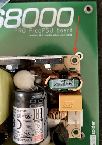
Clearly, the screw holes are not where I placed them on the mockup. Another lesson to actually have the parts in hand before I order the board.
On the plus side, as expected, the first version’s fitment into the case was absolutely perfect. Even though the thin metal of the power supply bracket was a little warped from being stored/washed/sanded/painted, it still looked very good. Although I was disheartened by the stupid mistake I had made, I was excited to see that most of it lined up. It looked real.

The fan header pinout was correct. I went around looking for some other minor changes to make in order to justify the re-spin, and blog friend Esteban Villalobos sent some of the pictures off to an X68000 Facebook group, where I received some great advice about what else to change from group member Dave Park:
First, the thermal reliefs I had set for the ATX connectors were not really appropriate. Rather than completely surround a pad with a given copper pour, KiCad attaches the pour to the pads using little “spokes” by default.
This is to make it easier to solder to the pin holes as you have to sink less heat into less copper, but it actually bottlenecks the effective width of my giant copper fills down to the tiny reliefs that connect them to the pads. You might remember that I had to use much more heat when soldering to the Mattsoft ACE board, which didn’t use these thermal reliefs, and now I know why.
Second, a 74LS04 is not meant to be used with its input pins floating. In fact, the datasheet even warns to tie each input to ground or 5V to “ensure proper device function.”
I fixed both of these immediately, and I’m grateful to Dave Park for the advice.
The Second Time’s The Charm
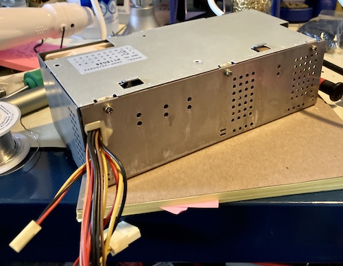
Soon, the second version arrived, and I mocked it up:
Beautiful! I held the Meanwell up on some M3 screws with vinyl spacers and double nuts to retain them, and got to building out the rest of the supply.
I crimped up 18AWG silicone-insulated wire to connect the PicoPSU to the Meanwell. The current-carrying capacity of 18AWG is an impressive 16A, which should be more than enough for the 65W Meanwell.
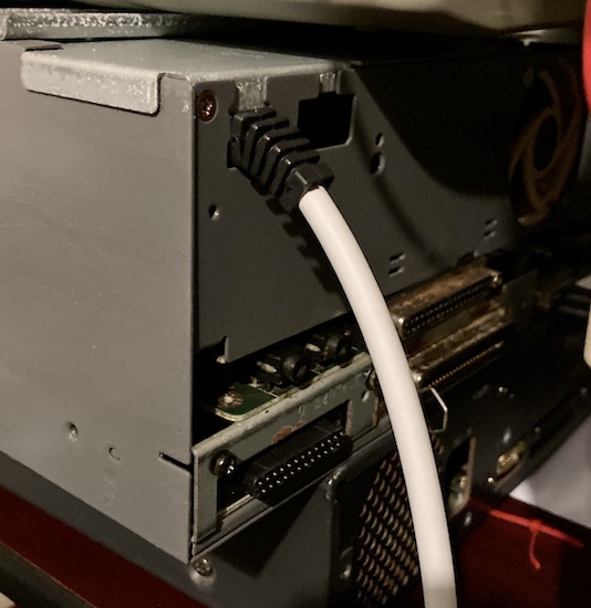
When I connected the wall cord, which is basically the same experience as documented in the earlier ACE power supply entry, I used some el-cheapo rubber strain-relief grommets from Amazon. They fit perfectly, which was a delight. The cord itself came from an Apple MagSafe power supply’s extension cord, and is a nice high-quality piece that was easy to work with, although I wish it were black so it matched the case better.
As always, I used an underwriter’s knot on the cord. You should too!
Ferrule and Preposterous
Another difference from the previous supply build is that I used ferrule crimps for the wires going into the screw terminals. When I was doing the previous build, it felt sketchy to me to be sticking bare stranded wire into screw terminals. Only recently have I discovered that my instinctive revulsion was in fact correct. In case you’re also unfamiliar, a ferrule crimper swages a piece of copper or aluminum tubing around the stranded wire so the strands can’t “burst out” as the screw tightens, which could otherwise short to adjacent wires. Simple, cheap, and good!
The shape of the ferrule when crimped also provides a nice square “plug” into the screw terminal’s jaws, which helps with making a high-current connection safer and more reliable. The plastic sleeve on the ferrule also seems to add some strain relief, but that hopefully won’t be a major concern on this board.
On the very smallest wires, I had to fold them over to make them thick enough for the ferrule to bite into on crimping. Even the smallest size in my kit (22AWG) was too broad. Although I couldn’t find a specific confirmation, I figured this would be okay, because the folded-over wire strands would be surrounded by the ferrule metal on all sides. This may be another of those “do as I say, not as I do” situations.
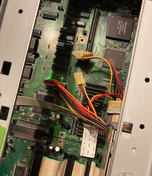
I spent a lot of time checking each wire from the old power harness to make sure it wasn’t corroded. The last thing I needed was a greened-up, high-resistance connection heating things up or causing unpredictable results or even a little magic smoke. Luckily, the conductors tested out pretty well!
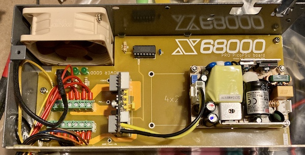
It was a bit of a tight fit getting the case closed with all the wires installed. I think a future version should move the screw terminals a little further apart, and mandate that they be both pointed in the same direction, so the wires in the back (12V, 5V) don’t have to do an ugly 180 to come out the case.
I considered desoldering the connector and flipping it around, but I had just enough length on the main harness to get away with it, and I also didn’t quite have enough room between the two rows of screw terminals to install the ferrule strain reliefs.
As you can see, the main motherboard harness is quite shortened from before:
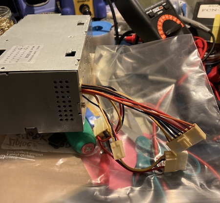
It is basically pure luck that it actually reached when test-fitted into the motherboard. I have learned nothing from all this.
Bench Test
Before hooking the assembled supply to the X68000, of course, I wanted to make sure it all worked on the bench. I plugged in the wall power cord, looked for the standby LED, and I was a bit surprised to see that the Meanwell came with its own standby LED. We’ll call that a redundant safety feature.
I pulled up the 5V standby line to the “power on” signal, and the supply jumped to life, with the “Power On” LED flicking on. The fan was turning happily at this point, and I took some measurements with my crappy multimeter, which all seemed to come out just fine without any load.
Installing it loosely into the machine, I reached down to push the power button… and nothing. At the active-high “power on” line, my multimeter was showing 110mV. Everything seemed alright with the +5V standby line, although it did dip to a worrying 4.59V by the time it reached the RP5C15 real-time clock IC.
I tore everything apart to look for a cause. The last link in the chain before the “power on” signal is issued is the transistor Q208, which itself is driven by a 74LS08 AND-gate nearby, but whose inputs are obscured by a maddening maze of vias and traces.
Everything seemed to test out okay. With my multimeter, I saw 0.03V at the output of the transistor when the power switch was on, and 0V when it was off. Seemed very weak, but the 74LS08 seemed to be acting properly, producing 3.5V on that output when both of its inputs were high (i.e. the computer was off.)
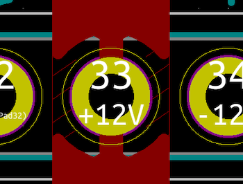
After consulting mattsoft’s board again, I found that my PSU board had a pretty major logic error. I managed to screw it up by putting a pullup on the inverter’s output rather than its input:
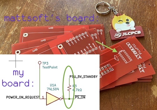
Without the pullup, the output of Q208 is not going to be a useful logic-level signal to the inverter, which means it just won’t work. An easy enough fix, but it’s a little embarrassing that it’s the only actual “logic” on this board, and I still screwed it up.
I bodged a pullup across the 74LS04 IC inside the supply, from pin 1 to pin 14, and shoved the supply back into the computer. Would it start?
It Started
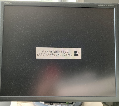
I’ve never been so happy to see the green LED on the 1970NX monitor light up.
Everything appeared to be in order, and the picture is solid. Overall, the PRO seemed to be in much nicer condition than my sickly ACE.
Of course, this is a bit of a bare boot. I did it without drives, cards, or most of the screws. This makes it a good baseline, if nothing else. Newly resurrected, the computer even soft-shuts-down on its own when requested, with the blinking LED and everything.
I was extremely pleased with this result! Now, it needed to do something useful. And that would require disks.
Repair Summary
| Fault | Remedy | Caveats |
|---|---|---|
| Original fan is corroded. | Replace with Noctua unit. | Connector is different between original and Noctua fans, requiring adapter. |
| Power supply is damaged. | Spend a bunch of time and money making a whole new power supply. | |
| New power supply does not boot. | Remember how pull-ups work and bodge board. |
More info
The Gerbers, assembly instructions, and KiCad source files are available on the GitHub repository. In keeping with the license of the original mattsoft work, it is also licensed under GNU GPL 3.0.