Will It Short? A Tandy 1000SX motherboard inspection
Tags: computer tandy tandy1000 tandy1000sx ram repair failure
Last time on the Tandy 1000SX show, I blew a hole in a power-supply capacitor without even getting the machine to boot. Talk about ungrateful! At least it gives me an excuse to buy more tools.
So, as anyone knows, old caps are the only thing that ever goes wrong on electronics ever. This is just an indisputable science fact. Humour me, though: what if this machine’s general unpleasantness and horrible death was caused by something else?
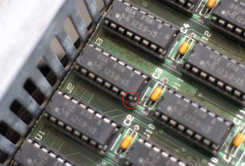
I took a quick poke around the RAM sockets, to make sure that nothing got stuck in there and there was no obvious damage. With all the metal case trim removed, I could now see all the chips and around the edge of their sockets.
Funny thing about U3: the voltage-feed pin on its socket looked damaged, like the plastic had melted around it. It was so subtle you’d probably never notice it unless you were looking super-close at a bare board, like I was.
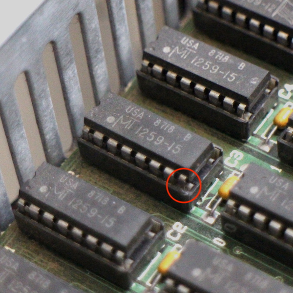
I pulled the chip, and (eventually) noticed that the VCC pin looked burned.
Maybe this RAM chip shorted and took out the power supply!
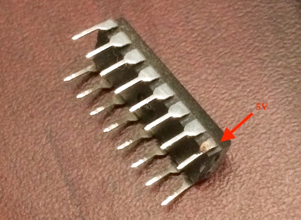
Something doesn’t make sense about that theory: VCC on this MT1259 DRAM chip like this is supposed to be positive five volts, not negative twelve. It’s a “newer” kind of RAM chip (similar to a 41256), one that doesn’t need negative voltages for DRAM refresh, unlike its popular friend the 4116.
Now that the chip had been removed from the motherboard, the socket looked fine - not even melted - which means I was probably looking too hard for a physically obvious cause for a problem that is going to be a bit of a boring slog to figure out. Still, while it’s out, we might as well check the chip itself with a multimeter to see if it’s shorted.
Once removed from the board, the VCC and GND pins on the chip didn’t report a short, but the socket left behind in the board sure did - both the VCC and GND pins of the socket were continuous with the case!
And when I probed the power supply connector on the motherboard, things got even worse. Of the nine pins going to the motherboard, seven were continuous with the case. I wasn’t sure which were “actually” ground and which were intended to be live, but I was pretty sure that you’re going to want more power pins in a computer than just two.
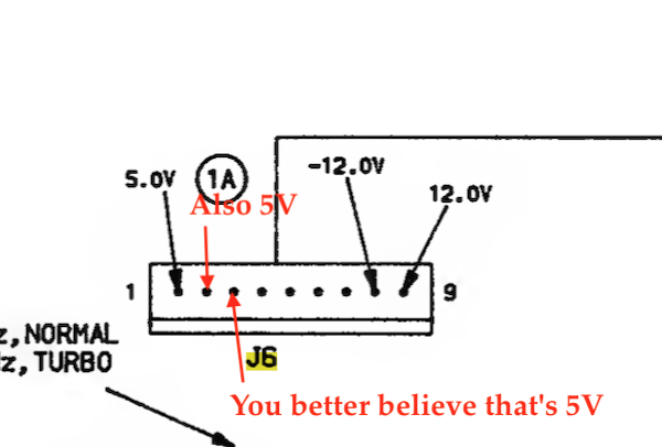
After checking the SAMS manual and the official Tandy manual, I found this:
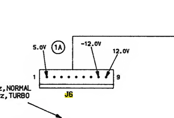
It’s a little odd there’s only one 5V rail to the motherboard (the floppy drives get their own dedicated 5V rails), but this means that, as you’d think from the test of the RAM socket, the motherboard’s 5V rail is shorted. But how did I blow up a cap on the -12V rail from this? And what part of the motherboard is shorted?
The Big Short, by Tandy Motherboard
There were a lot of places to look for a dead short on this board, and obviously the RAM is a strong suspect.
I looked at the RAM and found eight dead or otherwise unusable MT1259 DRAM chips. There’s the aforementioned burned-up U3. U9, U11, U12, U15, U5, and U7 all had dead shorts. U2 had a short, but the multimeter beep for it was extremely quiet - maybe some kind of partial short. The bad RAM chips weren’t all the same model (both -12 and -15 MT1259s had died), nor were they in the same bank.
In the video RAM section near the CPU, three out of four MT4067 video DRAM chips were bad - U31, U34 and U24 all tested shorted between their ground and power pins.
When I looked at the datasheet for the 4067 and 1259 chips, I noticed that the maximum rated supply voltage was 5.5V. The Tandy service manual says that the power supply will only go into overvoltage protection above 5.8V. That feels like a pretty big gap on old chips such as these. An overvoltage condition could explain why a lot of these three-decade-old RAMs packed it in.
Even with all the RAM chips removed from the board, I still had continuity between +5V and the case. Something else was to blame than just the RAM.
I checked the remainder of the socketed chips on the board (except for the large Tandy PLCCs; but if those were shorted I’d be unlikely to ever find a replacement and the board is junk anyway), but found no more obvious shorts.
Actually, I’m An Idiot
Before desoldering the entire board, I noticed that there was a 33Ω resistor hanging out in the middle of nowhere. Probing it, the continuity meter beeped. That’s weird. That shouldn’t be shorted.
I asked a friend who actually knew what he was doing, and he responded that a 33Ω resistor probably would beep on a continuity test since it was so low. To confirm, I pulled a 33Ω out of my parts bin and probed it. Beep.
With this newfound knowledge I began to get a sinking feeling. What was the resistance of the 5V-GND circuit? I had never bothered to check before hooking up the continuity tester. Putting my el-cheapo meter into resistance test, I touched 5V and case ground and took a look at the screen.
26Ω.
Maybe the board wasn’t shorted after all?
After asking around, it was time to finally buy a piece of test equipment that everyone else seems to have on hand: a current-limited bench power supply.

The theory is that I would set the current limit to something low but realistic, like 0.25A, and then power the 5V rail on the board. If it immediately slammed into the current limit, then I’d know there really is a short, and I’d probably also be able to detect the faulted part in question, since it’s all 80s CMOS and the part will get extremely hot.
Flipping the Switch
Once the power supply arrived, I hooked it up and gave it a shot. At five volts and 0.25A limit, the power supply immediately went into protection. I turned it up to 0.5A before I lost my nerve and went back down to 0.25A. Obviously we really did have a short on the board - but where?
Still a little afraid of poking traces on a hot machine with my shaky hands lest I short out good chips (or, somehow, myself), I ran to the store and splurged on an infrared thermometer. You know, like race car drivers use to figure out what part of the tire is hottest.
I brought out my fancy new toy, pointed it at the running board, and… nothing different. Not a single chip seemed to be hotter or colder than the others. No component had changed in temperature.
Still an Idiot
Confused, I decided to see if I really was hitting the right pins on the PSU. That’s when I noticed that there were three red wires on the harness, not just one as the manual implied. Tandy service manual, you lied to me.
With the connections set up properly, I now had a bit of signs of life. I brought up the current slowly, and got the following results:
| Current (A) | Voltage (V) |
|---|---|
| 0.58 | 2.0 |
| 0.73 | 2.4 |
| 0.84 | 2.7 |
| 0.97 | 3.1 |
Now, if you plot that on a graph, it looks pretty linear:
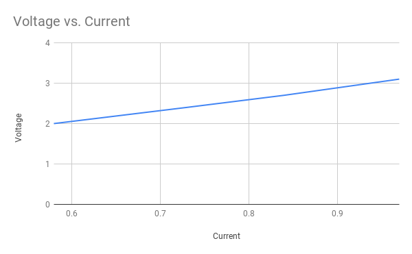
Is that the first graph I’ve had in a blog entry? Feels like it should have happened before now.
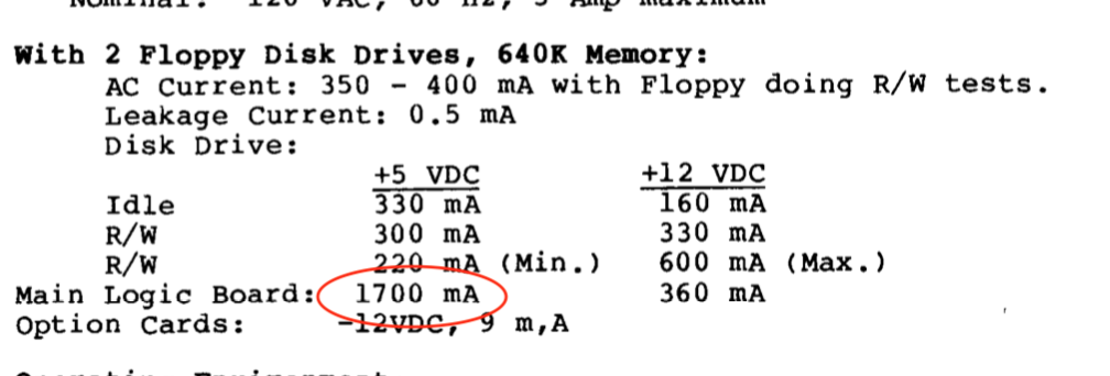
It seemed weird to me that it was only able to get up to 3V at nearly a full amp, but I’d honestly never done this before. With some nodding from my friends, I started twiddling it higher. The manual said 1700mA at the motherboard is not unusual:
Doing a quick spreadsheet regression on these four data points seemed to indicate that around 1.7A I’d see five volts, and then hopefully I wouldn’t need to raise the current limit any further.
So here we go. Cue nervously turning dials.
| Current (A) | Voltage (V) |
|---|---|
| 1.03 | 3.2 |
| 1.09 | 3.4 |
| 1.16 | 3.6 |
| 1.23 | 3.8 |
| 1.41 | 4.4 |
| 1.57 | 4.9 |
| 1.62 | 5.0(!) |
I was right! My regression was pretty much bang on. The slightly faster rate of voltage increase became most noticeable around 1.3 amps, but you can see it happening on the chart.
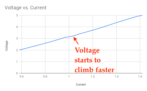
At around 1.62A, the machine stopped bumping up against the current-limit and we switched to voltage-limit, which meant that the motherboard was definitely not shorted on the five volt line.
This is great news.
Undoing Everything I Just Did
So now that I know my multimeter was lying to me, and also that the board wasn’t shorted, maybe some of that RAM was OK after all.
My plan for the next little bit:
- Reinstall the video RAM chips to the motherboard. It’s going to be a little hard to test video with three out of the four VRAM chips missing.
- Jumper the motherboard so that it only wants to use 320K. I don’t have enough RAM chips for the full 640K - even if the ones that reported shorted were still good, there’s no way I’m reusing U9 with its burnt leg. I have some Korean 4164s that might work, but I’m still not sure if the “A8” pin on the Microns I took out of this computer is actually used1.
- Replace the capacitors on the power supply, and then use a test bulb and a burly multimeter to see if it really was “just capacitors” after all.
I’m pretty excited that, at least from a current-draw perspective, the board isn’t quite as dire as I originally assumed. Let’s see if I can make a Real Computer out of it!
-
Hi, it’s me from the future. 4164s are 64K x 1 DRAMs, MT1259s are 256K x 1 DRAMs. You cannot use a 4164 in place of an MT1259. The extra address pin (A8) means that the MT1259 is 9 rows x 9 columns, or 262,144 bits (2(9+9)), as opposed to 8 rows x 8 columns, which produces a mere 65,536 bits (2(8+8).) 41256 would have been a better choice here. Sorry to anyone who was confused. ↩