Tandy 1000SX power supply is back from the dead
Tags: computer tandy tandy1000 tandy1000sx power-supply repair
When we last encountered the Tandy 1000SX, it decided to bravely blow itself up rather than face us in battle. With a lot of elbow grease and a little bit of solder-slinging, this testament to 80s shopping-mall computing will live again.
Last time, the C23 capacitor blew out on the power supply. According to the service manual, this capacitor is important for the -12V line.
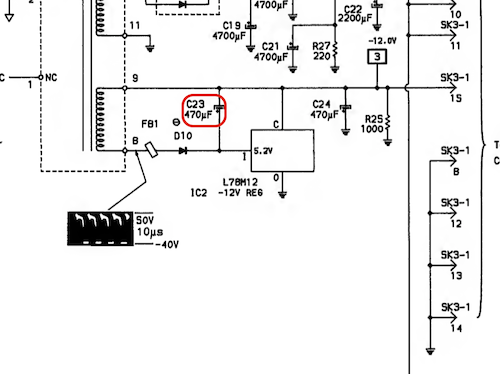
Most modern ATX supplies do not have -12V; so what was it used for? Usually on older computers, some around this age, negative voltages (at very teeny-tiny currents) are required for DRAM refresh. Eagle-eyed readers will remember that this machine was sold with a RAM problem - could these two be related?

Apparently I’m only supposed to get this power supply serviced by Radio Shack, which I figured would not be too hard. It took me a little bit of digging around, but luckily my local vintage bookstore had a copy of the phone book from 1989 in stock. However, when I phoned the number the phone book had listed for a “Radio Shack service centre,” it was now some kind of donair place. The guy who answered was very helpful (and the garlic sauce was amazing), but unfortunately he had no particular advice about what other parts I should buy to get this power supply back into like-new condition.
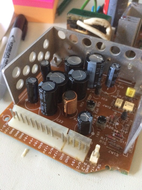
The first step of opening the power supply is to pry off the friction-fit metal shield that holds the power socket and the power switch, then undo the little connector.
When I unscrewed the board, one corner snapped right off without any pressure. I’m hoping this was a shipping problem.
At first, I thought this was just a chunk of ground plane. I didn’t find out until later just how important this little piece of broken off board really was…
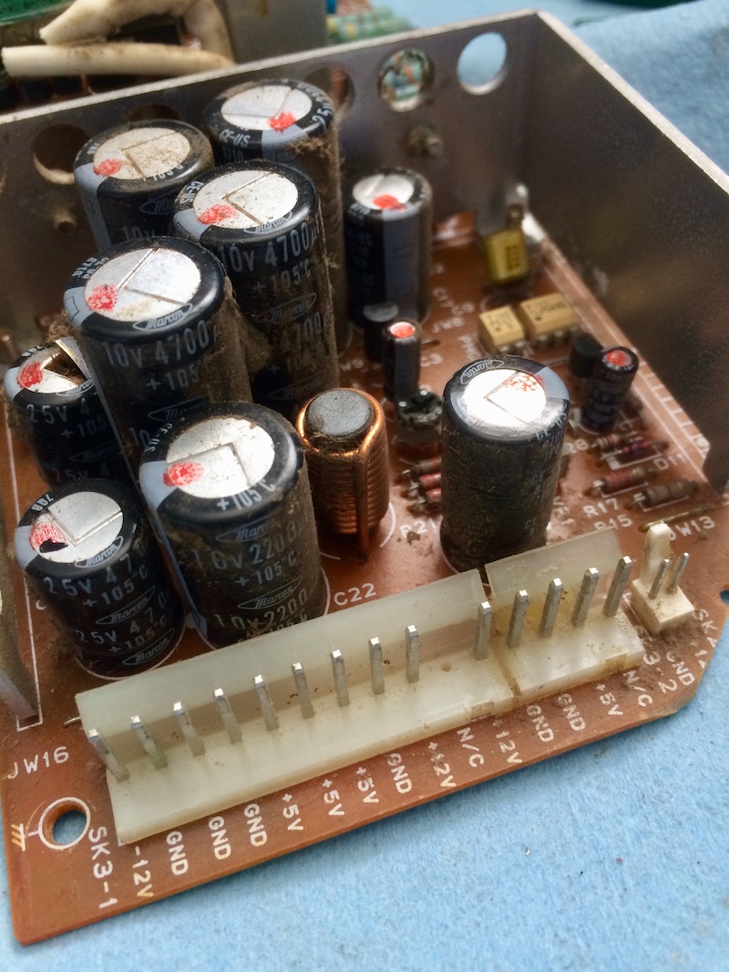
I fought for a long time to get the Molex connector off the back of this power supply board. I’d never even seen one with two tabs before, and even once the tabs were released, the connector was practically welded onto the pins with heat expansion and corrosion from age. I actually ran out of spudgers trying to keep the tab loosened while tugging on the connector and had to resort to auto body trim tools. Still not as much blood as the Amiga 2500’s motherboard power supply connector, but it was very very close.
Blasting the PCB with an air compressor only cleaned some of the gunk off. I was picking greasy dust bunnies out of this thing the entire time. That’s what you get for running a huge fan directly over the board - can’t imagine that the extra insulation from the thick blanket of dust did the supply any favours.
An actual recap? On this blog?
For starters, I figured that all the giant electrolytic cans that were siblings of the departed should also be removed. This consisted of:
| Cap ID | Capacitance | Voltage | Comments |
|---|---|---|---|
| C6 | 680µF | 200V | Mains filter cap. BIG. |
| C15 | 1uF | 50V | |
| C16 | 2200µF | 25V | |
| C17 | 470µF | 25V | |
| C18 | 1000µF | 16V | |
| C19 | 4700µF | 10V | |
| C20 | 4700µF | 10V | |
| C21 | 4700µF | 10V | |
| C22 | 2200µF | 10V | |
| C23 | 470µF | 25V | |
| C24 | 470µF | 25V | |
| C25 | 1uF | 50V |
I decided to leave C6 alone after asking around. Other people who have rebuilt similar power supplies said that this cap, being on the mains side, is a little special - high-reliability - and they fail very rarely.
Because I had quite a few caps to do here, I finally retired my works-once-in-20-pulls Pace 1980s desoldering station (ex-RCMP!) and picked up a nice modern Hakko FR-301. It is so choice. If you have the means, I highly recommend picking one up.
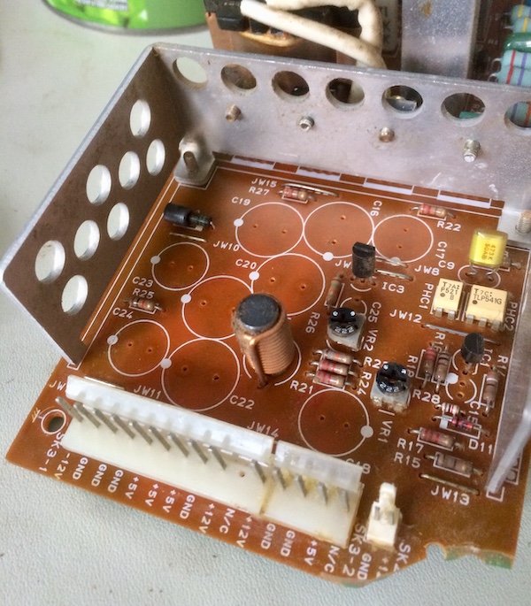
Putting the new caps in was pretty easy as well. They weren’t all quite the same size (electrolytics have improved since the 1980s, I’m told), but they all fit.
I also made sure to clean up the flux, dirt, rust and old-looking solder at this point. There was no reason to reflow every joint, but some looked especially dry or had insufficient solder, so they got touched up.
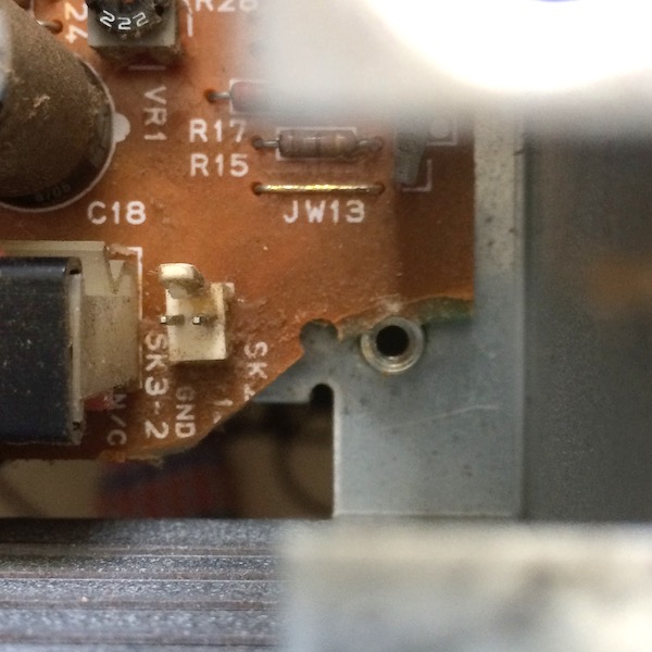
Remember that corner of the PCB that was broken off? I got tired of looking at the ragged corner, so I super-glued the board back together. When I first removed the power supply, this piece was hanging broken around its screw post, possibly from shipping damage or old age.
At first, I figured this was just ground plane - didn’t matter if it was there or not. When I reattached this corner of the board, I realized that it actually served five volts to some components on the corner of the board. The multimeter reported that this pin and all of the 5V pins were discontinuous, so the trace was definitely severed.
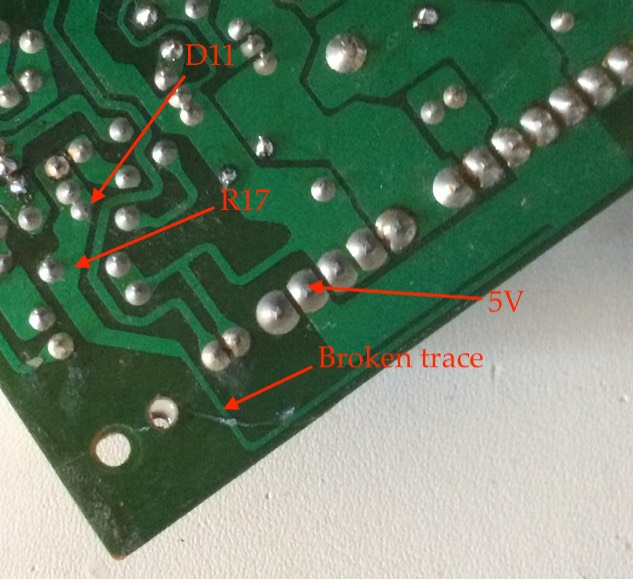
I don’t know if that would have affected the power supply’s proper operation, but I’m guessing Tandy was not in the habit of putting components on the board that they’re not going to use.
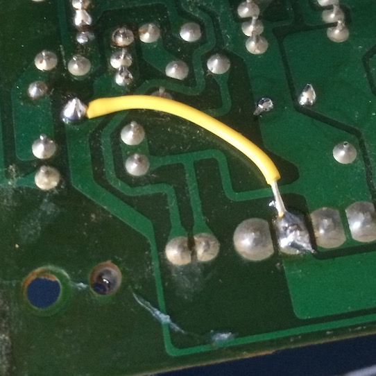
I did a quick patch wire here so that 5V could get to at least one component of this plane. Don’t worry: I cleaned that ugly glob of solder up after I took the picture. Kind of.
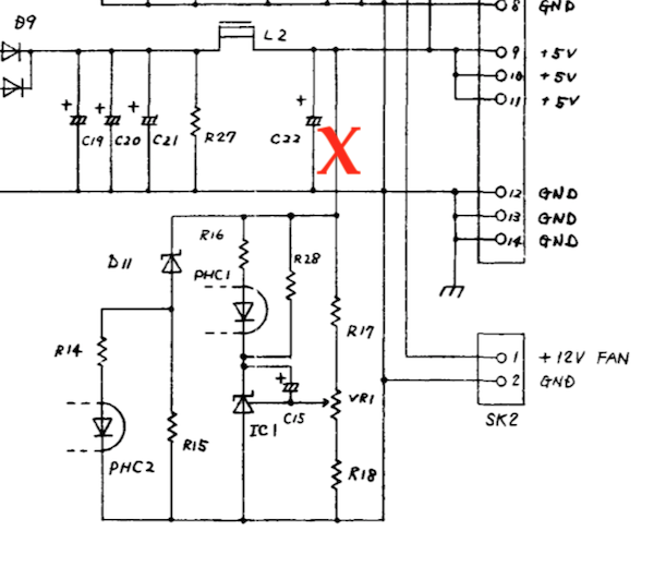
If the schematic is accurate, I probably lost a lot of pretty important functionality. PHC2 controls overvoltage (“crowbar”) protection, and PHC1 controls load-related regulation for the five-volt in the first place. Hopefully the lack of these signals didn’t cause any “damaging oscillations,” as the manual states will happen if you run the supply unloaded.
Load Me Up
Speaking of running the supply unloaded… I looked at the power supply board, couldn’t find any more holes or missing components, and decided it was probably time to test. We need to set up a dummy load before we can throw the switch.
Luckily for us, the Tandy 1000SX service manual has this table for minimum load:
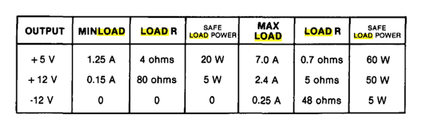
1.25A seems quite high to me, but remember that in the previous entry, the motherboard needed almost 1.7A before it would “do” anything.
I thought about putting something together with car tail light bulbs (1156s are usually around 20 watts), but in the end I decided to splash out for some fine Aliexpress electronic loads - one each for both 5V and 12V. I think that makes these the fourth and fifth tool I’ve bought for this machine alone.
If this entry were a movie, this is where you would insert the montage of me waiting for shipping from China. At one point, I took up gardening. My carrots are coming in just fine, thanks for asking.
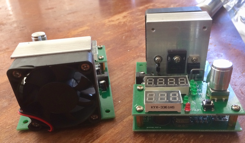
Hello, new friends! These didn’t come with their own power supplies. The ad said that they were 12-volt power supplies, but none of my 12-volt router bricks had a tip that would fit. They were sent in a soft “ePacket” bag, so a little bit of shipping damage occurred, but it was limited to the frame of the cooling fan.
In case you’ve never seen an electronic load before (I hadn’t), here’s basically how it works. We’ve all had the experience of a power supply that’s great when you don’t strain it, but it immediately falls apart when you try to ask for a lot of jam.
The electronic load’s idea is that you can dial in a specific amount of load and then see how the power supply reacts. It does this by wasting energy in order to maintain a constant current draw. Inside the load, a microprocessor or op-amp monitors the amount of current draw through a shunt resistor and runs a transistor to waste more or less energy. That’s why these need such huge heat sinks - the energy is converted into waste heat!
There are other kinds of electronic loads than just constant current (inductive and capacitive load testers), but I don’t need them for this project.
Where would I go for a universal power supply? Appropriately, I went to Radio Shack. Well, I went to The Source, as it has been called in Canada for the last few decades. They spun it off to Circuit City, and then when Circuit City collapsed, they got acquired by one of our telecom monopolies, so it’s not really a “Radio Shack” anymore, but it kind of is, and occasionally even has bags of Radio Shack-branded resistors, even though the store’s only actual purpose in life is to sell you smartphones and plans. Canada is weird.
Anyway, I got a pair of fairly beefy “RCA”-branded universal power supplies with 12V output and a tip that fit.
So, just to make sure you’re following along, here is the list of power supplies involved in testing an 80s switching power supply:
- The original Tandy power supply;
- The bench power supply I used to make sure the motherboard wasn’t shorted in the previous entry;
- Two 12V power supplies for the power supply load testers themselves;
- If you really want to be pedantic about it, the batteries for the multimeters are also power supplies.
No wonder all those old electronics dudes never throw away a wall wart. Hopefully the oscilloscope doesn’t have to come out.
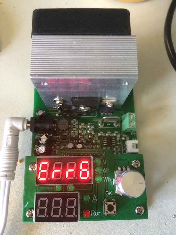
Unfortunately for me, one of the testers kept reporting this Err6 error, which seems to be related to an inadequate power supply. The other tester worked fine with the exact same power supply, and both “The Source” supplies are 12.22V and 12.26V unloaded (plenty of headroom.) The bench supply also wasn’t able to placate it.
So, I contacted the seller, while placing an order for another tester from a different seller in the meantime. Then I found out Amazon had a third kind of tester, available for a few bucks more, same-day delivery.

It’s Testing Time
Now that I had no more excuses, it’s time to steel my nerves and hook up the power supply to test. Here’s what the setup looked like:
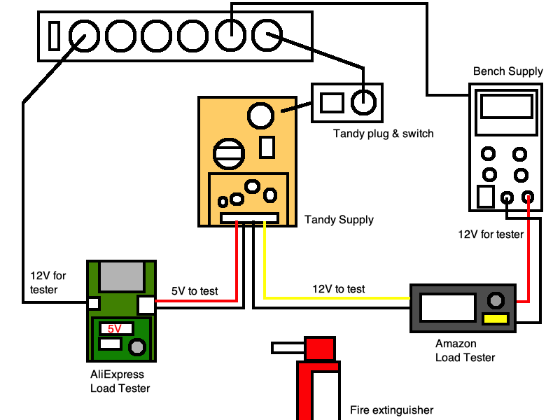
Only the original AliExpress loads had a barrel jack, so I had to use the bench supply and alligator clips to power the screw terminals on the Amazon load.
Here’s what that looked like on my desk:
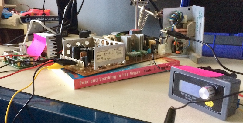
I set up the power supply, double- and triple-checked my list, got a fire extinguisher, steeled my nerves and flipped everything on.
Here’s what I got:
- On the 5V rail, at 2.0A, I got only 4.79V. This is pretty low, but I’m a little afraid to touch the 5V pot right now until I get an isolation transformer.
- At 2.5A, the 5V rail dips to 4.74V.
- At 3.0A, the 5V rail dips to 4.68V. Since the 5V rail is supposed to go up to 7A, this still feels low, but I’m unlikely to draw that much current with this machine.
- The 12V rail is 12.39V at 0.20A.
All voltages seem rock solid. And that’s how I spent two entire months diagnosing, rebuilding, and then testing a switching power supply!
Next up, I’m going to try and see if I can get the computer to boot.
Repair Summary
| Fault | Remedy | Caveats |
|---|---|---|
| Power supply cap exploded. | Replace electrolytic caps. | Did not replace ‘main’ cap. |
| Regulation portion of power supply fell off. | Glue back on. | May not be a good long-term fix. Should have soldered a jumper wire instead. |