Foiled again by the Tandy 1000SX
Tags: computer tandy tandy1000sx repair failure
We fixed the 1000SX’s power supply, and tested the motherboard for shorts. There’s nothing left to do but put the computer back together again and see if it works. And take it apart again. And to wish I had a fully-operational chip fab and precision schematics of every custom IC. Yeah, this one is gonna take a little more time.
Not a Big Fan
To treat myself, I bought a fancy new Noctua 80mm fan to get rid of the factory leaf blower, but only once I got it home did I realize it’s too efficient for the Tandy.
The original fan consumed 2W, which meant the power supply was asked for 0.16A on the +12V rail. That’s just slightly above the minimum load on the +12V rail of the power supply, as we established last time:
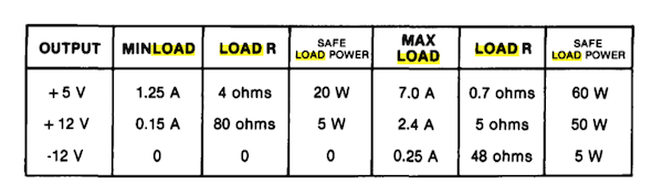
The Noctua, being 32 years newer, only asks for 0.035A, which I think we can all agree is a lot less than 0.15A. Seeing as I don’t want to fix the power supply again, I might as well stay within the safe parameters.
I’ll probably add my new dead-silent future fan back into the machine when I find something else to suck down 12V current, or change to a more modern power supply. A 5.25” floppy drive only has a 12V draw when the motors are going, and a Gotek doesn’t use 12V at all.
First light, disappointing
I put the power supply into the machine, connected the old fan, bolted things down just tightly enough so they wouldn’t implode, and then plugged it into my PVM. There was a flash on the screen when I powered it up, but no video appeared, there was no noise from the internal speaker, and there was no indication of composite sync being established.
That’s pretty much where we were at when I first got the computer, except hopefully with fewer explosions.
Toggling the CGA/monochrome-composite dipswitch on the motherboard didn’t change anything - still flashed on the TV in both modes. Maybe the white flashes were just the composite video circuitry powering up, and not actually doing anything at all. The machine was halted, or in a state that I otherwise didn’t want it to be in.
Voltages looked solid and at the Molex floppy connector - 5.01V, 12.46V - so I knew the power supply was working properly and the board wasn’t dead shorted. I attached a spare UltraSCSI hard drive (what, you don’t have one?) to make sure that there was enough supply draw, but it seemed to make no difference. The RAM, CPU, and VRAM chips seemed to be seeing a solid 4.84-4.86V at their power supply pins.
Using the old mk1 finger was a little illuminating. When I realized there was no short on the motherboard, I put the three VRAM chips that had buzzed on their continuity test back into the board. All three of those chips - and not the “good” VRAM chip - were extremely hot to the touch after only a few seconds of running! Unlike the 4067 video RAM, I didn’t put any of the “bad” 4164 work RAM back in, since I had just enough to populate Bank 0, and set the jumper for 320K as such.
Were the MT4067s to blame? Could be, but I didn’t have any ‘known good’ chips to test against. Would the Tandy still work with three-quarters of its video RAM missing? I yanked all three of the ‘bad’ ones out, fired it up with the ‘good’ one in U35, and saw no difference other than that the voltage was now 4.92V.
RAM it in
With some help from others, I was tipped to replace the MT4067s with much more common 41464s (also commonly known as the 4464). Jameco had a pile of “reconditioned” DRAMs, so I placed an order. Getting parts from America? Nothing could be more Tandy-like.
They showed up a week later, and I immediately slipped them into their sockets. Even if this didn’t fix the problem, I figured, missing 75% of the video RAM is not going to make my diagnosis any easier.
With the new VRAM in place, all four (3 new, 1 old) VRAM chips were running stone cold when I started the machine up. I used an infrared temperature gun to figure out that some of the RAM was running a little high after 1 minute:
| RAM chip | Temperature after 1 minute |
|---|---|
| U1 | 43°C |
| U2 | 27°C |
| U3 | 27°C |
| U4 | 25°C |
| U9 | 30°C |
| U10 | 46°C |
| U11 | 55°C (wow!) |
| U12 | 27°C |
RAM Doubler
Obviously, it was time to dip into my baggie of eBay 4164s from Korea (Samsung KM4164B-15). Even though these chips didn’t test out as ‘shorted’ when removed from the machine, they sure don’t seem to be real healthy.
I replaced U1, U10, and U11 - but to no effect. The machine still did not work. Touching U1, U10 and U11 felt cool to the touch, which was nice. However, U2 and U12 were white hot - but the temperature gun reported differently!
Well, apparently my crappy temperature gun’s laser sight is not very accurate at close distances. In fact, it’s almost a full inch off! At the range I was using it at, it was actually reporting the neighbouring chip’s temperature when the laser was on the chip I meant to read.
Keeping this in mind, I resorted to once again just using my finger. U2 and U12 burned me, so I assumed those were “hot.” Swapping those out for “new” 4164s produced no new results, other than that the RAM was now cool to the touch.
Logic Probing
With everything physically obvious out of the way, my next step was a logic probe. I recently got a Tek 2246, but I’m a little intimidated by it still, and wanted the comfort of an uncomfortable too-short wire, clips that fly off, and incessant beeping to hold my hand through this diagnosis.
Some immediate discoveries:
- RESET is always low. The CPU should be reset at some point during the startup process, or when you jab the reset button.
- CLK is always low. It should be, you know, a clock.
So timing and reset are not working at all. Who controls timing and reset on the Tandy 1000SX? The service manual says:
The next major functional block of the Tandy 1000 SX is the CPU control and timing chip (light blue). A block diagram of this 40 pin custom part is shown in Figure 5. This chip accepts 16MHz and 28.6 MHz clock signals from the master oscillator circuits and generates clocks for all of the other circuitry on the board. This chip also generates the system reset signal and derives the CPU control signals based on status inputs from the CPU chip. The last major function of this part is to generate timing signals and a chip select signal for the FDC.
Thanks, manual. So which chip is “Light Blue?”
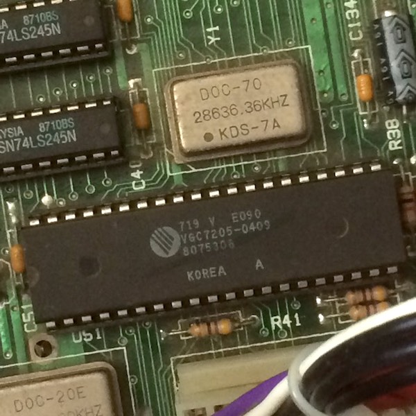
In this machine, it’s U51. The motherboard schematic says that it does indeed use or provide a lot of the pins we’re looking for:
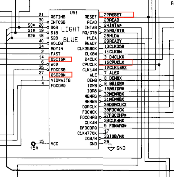
| Pin | Does what? |
|---|---|
| 14 | 16MHz in (OSC16M) |
| 27 | 28MHz in (OSC28M) |
| 16 | CPU clock (CPUCLK) |
| 21 | Front panel reset (RSTIN8) |
| 22 | Reset (RESET) |
Pin 16 is the CPU clock, and pin 22 is the RESET output from whatever logic lies inside this little custom guy. Is the CPU clock firing? Are we getting anything on the clock inputs?
Not a single one! No clock inputs, no CPU-clock or RESET outputs! When I push the reset button on the front, the RSTIN8 pin doesn’t lift from low!
Let’s look at RSTIN8’s circuit first:
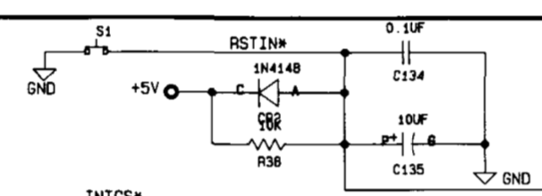
Wait, star? 8 and * are the same key… does this mean it’s meant to be active low?
The diode - my usual suspect for being shorted - can’t be shorted since that would pull RSTIN* high all the time, until I push the reset button, and then the machine would out. Maybe a cap is bad?
I pulled and replaced C135 because I love my Hakko FR-301, but it made no difference whatsoever. The old cap tested out fine on my tester, and the machine still didn’t work.
I spent a little more time diving into the reset circuit, and I found out the button only had 1.05V until pushed. When pushed, the voltage across the switch would drop to zero volts. The logic probe doesn’t consider 1V to be a valid non-zero voltage (in either TTL or CMOS modes), so no wonder it wasn’t reporting anything. A voltage that low seemed wrong, somehow, like someone in this circuit was pulling too much power.
I kept tracing around but couldn’t find an obvious culprit. I even cut C134 out of the circuit entirely to see what would happen, but there was no difference.
There was nothing to do now but break out The Scope.
The Great White Scope
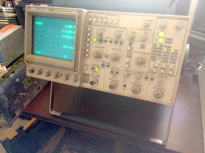
I picked this up a few months ago. Some part of me always knew I was going to have to teach myself how to operate it on this Tandy. When the logic probe and the multimeter fail, it’s time for the Tektronix 2246.
Your multimeter can basically only report what voltage it’s seeing on average. It can’t tell you if that voltage is pulsing like a CPU clock, or if it’s constant, like a really broken CPU clock. If I could see the waveform, I’d know for sure what the clock is up to. That kind of thing is what the scope is meant for.
After a lot of dial twiddling, probe acupuncture, and confusion (the manual only makes sense if you already know how to operate a scope), I eventually managed to get this picture of the 28MHz clock coming into the “Light Blue” U51 chip:
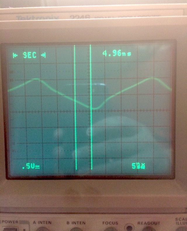
That doesn’t look like a good clock signal to me. In fact, just like with the reset button, the voltages are suspiciously low (a mere 0.36V to 1.10V, when the datasheet for the oscillator says you should be seeing 0.4V - 2.4V).
On the plus side, the frequency seems to be right. Even if you don’t use the nice time-measurement tools on the scope and just eyeball it, peak-to-peak distance is roughly 7.5 5ns squares, and 1/37.5ns = ~27MHz, which is really close to 28MHz. So it’s still a clock, just a lumpy weak one.
I scoped the main power supply at this point, and observed that the five volt line was pretty stable - only a 0.18V peak to peak difference. At least the power supply repair worked out.
With the now-suspect Light Blue chip removed from its socket, the voltage levels at the input pins now looked like they were supposed to, with 0.86-2.94V on the 24MHz clock and 0.60-3.5V on the 16MHz. I also saw a solid 5V across the reset switch until I pushed it. Had the Light Blue chip come down with some kind of internal resistance, and started pulling all of its inputs down in a fit of silicon jealousy?
Since the Light Blue chip is custom, it’s not like I can just pop out to Digikey for it. My only option is to find another Tandy 1000SX, or at least a parts motherboard for one, and see if the Light Blue from that machine works in this one. At the very least, it seems as if the 1000EX also uses the same chip, so I hopefully have a lead on getting a new one.
Inconclusion
I’m not going to lie, this is a vast disappointment, especially after all the time (and cash) poured into the machine so far. However, I know I’m closer than ever to getting this SX up and running again. They made more SXes than any other Tandy 1000, so hopefully there are lots of parts out there with other friendly hoarders hobbyists.