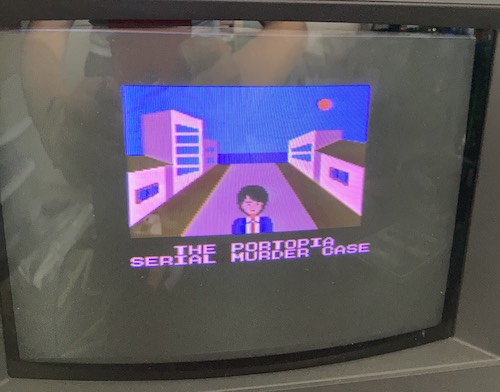
Let's visit Portopia
Tags: console nintendo famicom nes homemade-hardware homemade-software
In order to get to the bottom of a mystery, I had to put a lot of other mysteries in my way first. And then also build some hardware. At the end of this entry, I’ll have actually used old hardware to play a videogame. I’m scared too.
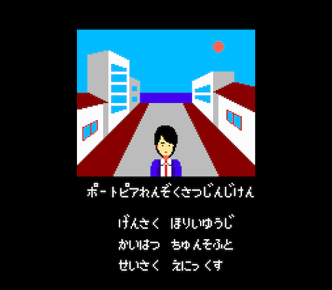
Portopia Renzoku Satsujin Jiken, or The Portopia Serial Murder Case, is a pretty influential 80s Japanese game. Originally, the game was released on the PC-6001, but it was converted and expanded later for the Nintendo Famicom, where it became an even bigger hit. Portopia defined the genre of a Japanese-style graphic adventure, and tons of other games followed in its wake. I wanted to see what all the fuss was about, but ideally without having to learn functional Japanese.
Since the game is so historically significant, it’s disappointing that it hasn’t been officially translated and released in the West. A group called DvD sweated bullets for months to put out a huge English translation in 2006.
There were a lot of technical challenges to overcome by the translation team, which is all the more impressive when you consider the translation was done early enough that they had to build their own tools to do it:
- Japanese is a much more compact written language than English, so when you translate you end up ballooning the script by a lot;
- The original game cartridge didn’t feature any mapper, so it was stuck with just 32K of program ROM and 8K of character ROM;
- Reportedly, only two bytes of empty space were left over on the original NROM cartridge, after the original Chunsoft developers were done packing everything they could into the tiny space they had.
There’s no room for all that English text. So the translation crew expanded the ROMs. This meant that they had to add a mapper so that the NES/Famicom could bank-switch the extra script text (all placed in program ROM) in and out of its address space. And then they had to rewrite parts of the game to know when to bank-switch. One hell of a project, and I’m happily wandering by and then trying to funnel all this work into a real cartridge - hopefully a much easier job.
I was planning on playing this game on the NES emulator on my DSi, but for whatever reason the emulator seems to crash hard whenever I bring up the phone keypad. And I’ve got an NES, so I might as well play it on the real hardware if I can.
What is a Mapper anyway?
At the most simplistic, a “mapper” is the mechanism inside an NES/Famicom cartridge that does bank switching. Since the 6502 has a limited 64kB address space, pretty much every machine with one has some bank switching support.
The original Portopia Famicom cartridge is what the community calls an “NROM” board (after the part number of the circuit board,) which contains no bank-switching support. You end up with 16kB or 32kB of program ROM, and 8KB of character ROM. Since the Portopia translation needs 64kB of program ROM, it stands to reason that we’ll need to do some bank switching - it’s bigger than the Famicom’s entire address space!
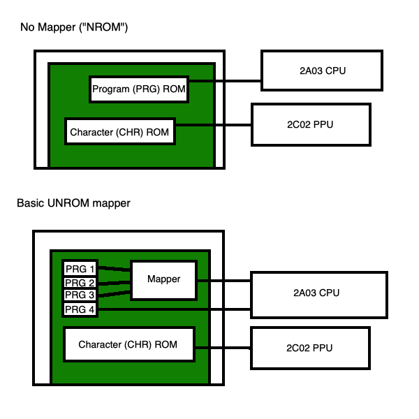
This diagram isn’t accurate to how it’s actually wired up, but hopefully you can kind of get the idea. A certain portion of the cartridge’s memory space goes through the mapper mechanism, which decides what part of the ROM to “return” to the CPU.
Some special requests from the CPU to certain portions of the address space (above $8000) will tell the mapper to switch which bank of the ROM it is looking at. This way, you can have a big program ROM, but only look at 16kB of that ROM at a time, with a sliding “window.”
In UNROM, the last bank of the program ROM is always mounted in the latter 16kB of the cartridge’s “memory space.”
As the NES and Famicom went on, cartridge developers started to add more sophisticated mappers. For instance, in the later Sunsoft games like Return of the Joker, rather than changing out an entire page of graphics (“character”) ROM, they could now swap individual tiles for animations. This required them to make some custom silicon, but when you’re producing a few hundred thousand units of a cartridge I’m sure the cost is amortized.
The whole concept is pretty fun - it turns even the most mundane cartridges into little pieces of expansion hardware for the NES. You could probably teach a whole digital logic design course using them as examples.
What does the mapper mechanism actually look like, chip-wise? We’ll get to that later.
Getting the Software
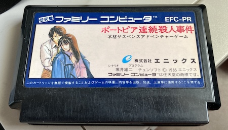
I grabbed a ROM from the Internet. As you can see above, I own the original game: I just can’t understand it. Since the new ROM is bigger than the old one, I wrote a quick Python script to imitate the translation team’s “ROM Expander Pro” Windows-only software. As an aside, I think newer IPS patchers can expand the PRG ROM without having to run this script, but it is still recommended in the translation’s README.
Once the ROM file was expanded to 72K (64K PRG + 8K CHR) I was able to apply the translation patch, which turned it into an English ROM. The FCEUX emulator seemed to have no problem playing it for a couple hours, so I assumed at this point that I was good.
I could stop there, but then I’d be missing out on some real hardware fun. How can I turn this ROM file back into a real cartridge?
Picking a Mapper
The original translation was done to use the Sunsoft-4 mapper (iNES Mapper 68) which uses a proprietary IC that would have to be salvaged from a real board.
I considered sacrificing a copy of After Burner 2, but with some more research, I found out that a user called lidnariq had made an UNROM patch. UNROM mappers (iNES Mapper 2) are much more common. Lots of games used this one because it was cheap and easy to implement, and only needed basic logic chips instead of proprietary ICs.
I applied the UNROM patch to my translated Sunsoft-4 copy, and tested the resulting translated UNROM version against FCEUX, which again seemed to work OK.
After searching the amazing NesCartDb to see which games were UNROM, I picked up a $3 NES copy of Casino Kid off Canadian eBay to sacrifice for the experiment.
Building version 1
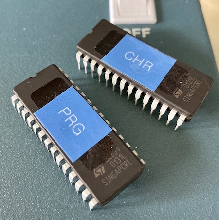
I used the webapp on rom.solutions to split the translated and converted ROM file into CHR and PRG ROMs, and then flashed those to a pair of 27c512 EPROMs that I had lying around from a Christmas gift. What, you don’t get stacks of EPROMs from your secret Santa?
Bring Me The ROMs of the Casino Kid
Before sacrificing Casino Kid, I looked around to see if there were any brand-new Famicom cartridge PCBs that I could just order for a few bucks. I didn’t have much luck, with many of the stores out of stock or sporting crazy shipping prices unless I bought a huge pile of boards. With the state of shipping out of China as bad as it was, I didn’t want to design one and then end up waiting months for it to arrive.
Also, with the way that I design boards, we’d be here for months while I keep finding and fixing backwards footprints.
One game-bit screwdriver later, Casino Kid was spilling his guts. It’s sort of appropriate to be using a Western console to play the translated game.
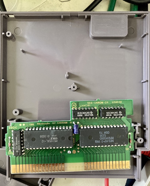
There you go:
- an OKI M5165AL-12 RAM chip for CHR RAM;
- a mask ROM (NES-KP-0) for program ROM;
- a 74HC32 OR-gate;
- a 74HC161 binary counter;
- and the CIC chip.
That’s all you need to make an UNROM board. This one is NES-UNROM-09, but an NES-UNROM-04 is virtually identical. Look at all that wasted plastic space that existed only to signal to consumers that they were getting a more substantial item than just a tiny toy Famicom cartridge.
Also check out the little solder blob on the jumper located near the bottom. This article would go on for miles if I had to also describe the hardware scrolling behaviour on the NES, but it’s worth pointing out that the games are set up - at the circuit board level - for either vertical or horizontal scrolling.
This one has the “V” jumper soldered, so I’m willing to bet Casino Kid is a vertical scrolling (horizontal mirroring) game. Portopia is a vertically mirrored game, so we’ll have to change this jumper to “H” for horizontal scrolling.
Wait a minute, doesn’t Casino Kid scroll in both directions? Ah, now the trap is sprung.
Also, without a battery, how are we going to save the progress in our murder investigation? Um… you can’t. The original Famicom version of the game has no mechanism for saving your progress, not even a password save. The same is also appears to be true for the PC-6001mkII edition, which makes sense as I can’t think of many tape-based computer games that can save back onto the original tape.
In the manual, the tech writers tried to play this off as a feature. You can keep track of what you did on a pen and paper notepad near your Famicom, and if you do things in a slightly different sequence, you will uncover different sides of the mystery and characters. I haven’t seen this so far myself, but every time I try to replay it from the start, I do actually end up seeing more scenes and get different items because I try something different this time. The game is also pretty short, though whether that’s deliberately part of the design or a consequence of the limited amount of storage available is up for debate.
Assembling the Board
Now let’s look at the chips to see if I have to do any rewiring. The stock board has 28-pin DIPs, so if you want to add a larger 32-pin DIP like a 27c010, you’d have to add some bodge wires and bend some pins. Luckily, a 27c512 is 28-pin, so we might get lucky. How do you get lucky? Research.
According to this guide on The Poor Student Hobbyist blog, a 28-pin 27c512 EPROM should have the same pinout as the original 28-pin mask ROM in Casino Kid and so we don’t have to do any rewiring - for the PRG ROM at least. Or so I assumed…
Let’s check the original CHR RAM just to be sure. I failed to track down a datasheet for this exact OKI SRAM, but the German version of Mega Man, which also put a CHR RAM chip onto a NES-UNROM-09 board, used the KM6264B SRAM chip from Samsung, which has a perfectly reasonable pinout.
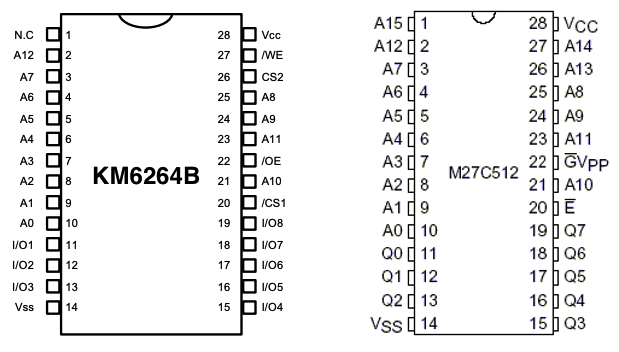
It’s pretty damn close! /OE on the 6264 maps to /G on the M27C512, which is what the EPROM’s output enable pin is called. The chip enable also lines up. The big difference is that since the 64kB EPROM is also much bigger than the 8kB SRAM, there’s a bunch of high address pins (A13 through A15) that aren’t being used as well. However, all of the other address pins and the data pins are in the right places, so if I copy the CHR data into the EPROM three times (which it seems the rom.solutions webapp already did,) I won’t even have to worry about tying the upper three address lines down. They can float all they want - and just index into identical copies of the data if they do end up floating high.
Geez, this seems easy. Can it really just be a chip swap? Out comes the desoldering gun…
I had to solder the ROM chips down to the board, because there’s unfortunately just no room for sockets inside the plastic of the cartridge. If I were going to do a lot of these, or were actively developing a patch, it would make sense to shed the plastic and put some sockets in. Then again, nowadays it would probably be easier to use an Everdrive or build a special PCB that can be re-flashed over serial.
The First Case
Once the chips were swapped, which took a surprising amount of work to clear the holes of all the old solder, I was able to reassemble the cartridge and test. Annoyingly, I just got either a CIC reset loop or a solid blue screen. Something wasn’t working.
I took the cartridge back apart and buzzed out all the lines to make sure I didn’t just do a bad solder joint, and cleaned the edge connector on the cartridge to make sure no leftover sticky rosin flux was contaminating the entire setup. Still no luck - what did I do wrong?
After a while more of frustration and reading many, many bits of information about how the 28-pin mask ROM pinout is identical to the 27C512, I decided to go look up the actual part that was originally in the PRG ROM slot and confirm it for myself. Casino Kid’s original ROM was a Ricoh RP231026D, and when I finally rooted through the internet and found a datasheet for it, I discovered this:
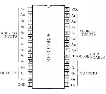
Remember five minutes ago, when I was blathering on about how the /G pin - pin 22 - is for output enable on the 27c512? It looks like this is a particularly large 28-pin mask ROM (128kB) and so they’ve jiggled some of the pins around from where I’d expect.
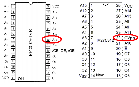
Since the PCB was designed for the Ricoh mask ROM, it thinks pin 22 is A16, so I guess the new PRG ROM was just never being enabled.
Shouldn’t A16 be low at startup, and therefore the ROM would be enabled, though? Yes, because even though the NES’ reset vector is at $FFFC, and you would expect A15 to therefore be the largest pin pulled high, the mapping circuitry pulls A16 high whenever A14 is high - thinking it’s an access to the last “page” of the PRG ROM. Once A16 is set high, it actually disables the PRG ROM entirely, and the NES just hangs.
I spent a couple minutes quickly buzzing everything out, to make sure I understood where this supposed “A16” pin was coming from, and I got about this far:
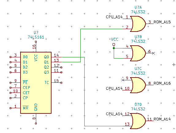
This would produce about four potential ‘pages’ on a 128kB PRG ROM, which squared with the two pages of the Portopia 64kB PRG ROM. After a bunch of notepad work, I managed to figure out that this seemed legit despite looking very weird at first, and then set about cutting the trace from the 74LS32’s output pin 8 to the 27C512’s /OE pin.
With a quick jumper wire between the 27C512’s /OE pin and its /CE pin, I felt confident. This way, a fetch into $FFFC would still return A14 & A15, so the NES would reach into the high half of the ROM to get the reset vector and therefore the entry point.
With a little more searching, I was told to ground out pin 22 (/OE) when doing a conversion like this. Even though I’m pretty sure that’s what I was doing with the /CE to /OE bridge, I tried it, but without any difference in results. I even desoldered and pulled pin 22 entirely out of the board, and then fly-wired it to a leg of the capacitor.
I desoldered and verified the ROMs to make sure I didn’t mix them up, and even re-split them using a different open-source tool. Nothing doing - I did everything right the first time. I even went back to make sure that the line I cut actually went to “A16,” which it did. What a stumper.
I headed over to nesdev to ask for help, and lidnariq (the author of the UNROM patch) responded within minutes and was super gracious and helpful about the whole thing. Kudos!
Flipping Over Boards Is Hard
I’ll save you a description of the next several hours of soul-searching agony and skip right to the good part: I had tied /OE high. I mixed up the negative and positive legs on the capacitor when I flipped the board over to solder to the underside, and had soldered to the positive.
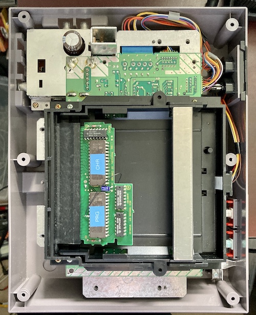
I only figured it out because I opened up the NES so I could get access to the PCB while it was running, for the purpose of logic probing. When I put the PCB in the first time, I had to push it down to make good contact. That put the PCB at a weird angle that broke the /OE patch wire loose from the ‘ground’ pin (I hadn’t soldered it very well while experimenting) and the game booted anyway, in its full glory. That’s weird, I said.
After I realized what I had done (about 15 minutes later,) it was just a quick resolder job to the other point and then the game reliably booted when inserted properly.
It seems in the end that the problem was two-fold:
- Even though the PCB booted fine when it was a Casino Kid, I must have contaminated the pins of the cartridge slot with flux residue or had inadequate pressure on the pins because the cartridge ‘case’ was only attached with one of the three screws. I had probably done this properly early on when I had
/OEand/CEconnected, but because of this the game wouldn’t boot properly anyway. - When I did pull pin 22, I soldered to the positive instead of the negative leg of the cap - pulling
/OEhigh so it would never be active.
In the end, I did eventually get to meet with my subordinate Yasu. He’s a real go-getter! Maybe after we figure out who greased Kouzou, he can help me clean the cartridge slot on this NES.