Unleashing the Power of the X68000 ACE
Tags: computer sharp x68000 x68000-ace power-supply repair mod
You might recall that I own a Sharp X68000 ACE, the world-beating, sprite-spitting computer of everyone’s dreams. So far, though, the ownership experience hasn’t been the most fun I’ve ever had. Repairing the battery damage in mine has been challenging, as the damage goes deeper than I first thought, but I have accomplished one thing so far: installing a more reliable power supply.
The power supply on all the X68K models is often fingered as a common point of failure on the computers, and making them reliable again is not always just a matter of high-speed cap swapping, as it is with other supplies of the era. Others who have repaired X68000 supplies said that even after repairing traces, blown capacitors and other components, the protective coating on the transformer wiring can erode away and short internally, wreaking havoc on the rest of the power supply.
Since I knew from the seller’s description in the original auction that there were soft-power issues, I was suspicious of the power supply, and thus decided to pre-emptively replace it with a PicoPSU.
As a bonus, I would be able to use the X68000 anywhere in my house, not just attached to the 100V stepdown transformer I use for other Japanese hardware. And that’s good, because with the amount of work the repair has taken so far, I fully intend to have it permanently installed and “on display.”
On the nfg forums, I found this great thread where hobbyist mattsoft built two new boards that fit into the existing power supply casing. I decided to build the “all in one” power supply, which contains an AC-DC converter to feed the PicoPSU, so that the X68000 could be plugged directly in to the wall with no need to hunt for a 12V power supply.
The first step was to order a PCB to hold everything. I grabbed the gerbers from the GitHub repo, and sent them off to JLCPCB. Since the shipping is still restricted from COVID, I had to pay more than I wanted to get rapid DHL shipping, which meant that the boards arrived super quickly in order to just sit on my desk for a few months while I was working on the rest of the machine. It cost about $7 apiece to make them after shipping - and I still have four left over.
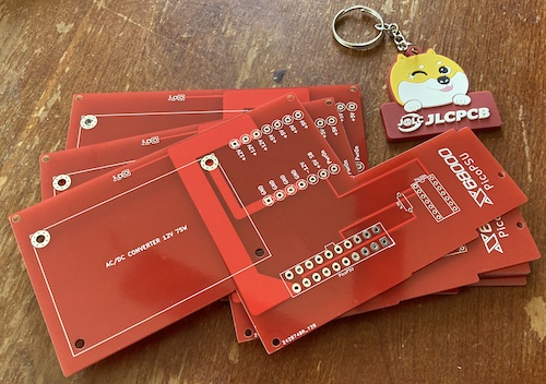
The GitHub repo for the “Easy PicoPSU v2” also offered an excellent bill of materials, which let me quickly order every part I needed from DigiKey. This got a little expensive, as the integrated AC-DC transformer is a costly component, but it’s still cheaper than trying to find a new X68000 if I were to nuke some custom chips with an original supply that was poorly repaired.
Soldering the supply together took a little more heat than I usually use. The board is excellent but it lacks the little thermal reliefs that KiCad inserts into my own boards when I do a big copper fill, so my humble Hakko iron was challenged trying to melt solder well on the big pads with a lot of copper around to sink the heat. I ended up going back with a bigger tip at a higher temperature and adding some more flux to make sure I had good, fully-flowed joints that were going to be reliable.
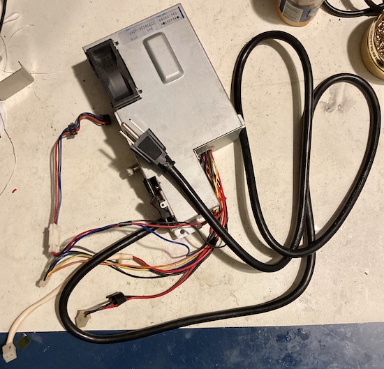
Getting inside the power supply to remove the old board wasn’t too hard. It has a bunch of screws around the perimeter (including some holding the fan on) and then the two halves of the metal case come apart. After that, there’s a bunch of tiny screws holding the PCB down. It’s gross in here, though, and I don’t think I’ll ever forget the smell.
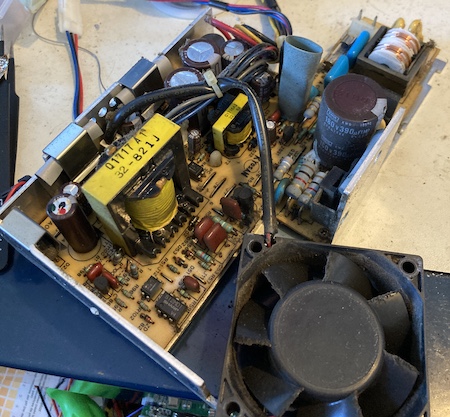
From the looks of it, I didn’t see much evidence of capacitor leakage. It’s possible that this power supply - by X68000 standards - was “pretty good.”
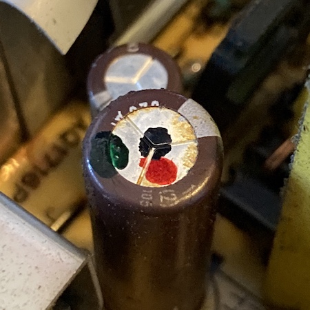
This cap had some staining on the top, but it didn’t seem to be capacitor electrolyte. There was a bit of an oily stain on the bottom of the case, so something was leaking, but maybe the machine was run in a super gross environment and this is leftover aerosolized cigarette tar or something. It’s probably just old flux, though.

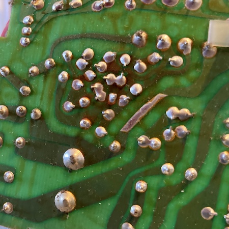
On the solder-side of the board, near where the oily stain is, these traces look a little dirty. Again, I’ve seen much worse.
I went about desoldering all of the wires - the ground wires were challenging to get enough heat into in order to remove them, but they too came free eventually, leaving me with a minty new harness with nice crimped pins on the end of each wire. It reminded me of the crimped pins from the Astec supply in the Bad ADB Mac LC, although this supply is made by Kyosan, a Japanese manufacturer I’ve never heard of but that is still in business making cool parts for trains and - apparently - funeral homes.
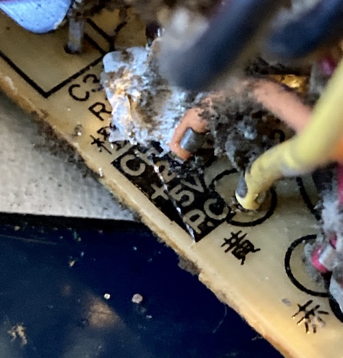
This confusing label in the corner is not really helping matters. By process of elimination, on the new power supply board, I have to figure out which wire “Power On” and “5V Standby” are supposed to be. Neither “CH 2” nor “5V P.C.” are obvious candidates for those, so I cheated and went online to ask the designer of the board what these cryptic hieroglyphics could possibly mean. From the nfggames page on swapping power supplies, I worked out that yellow is “Power On” and orange is “5V standby,” but only after I had already asked a bunch of other people. I must have completely missed the sidebar with the little pictures on the right because my browser window was too narrow.
After reading more about the X68000 soft power system, it appears that “CH 2” is also used - I believe incorrectly - in these community schematics to refer to the /PSON signal triggered by the front panel power switch. I still have no idea what it stands for.
Here are the wire colours I figured out from reading the labels on the PCB and consulting the web:
| Wire Colour | What Rail Is It? |
|---|---|
| Black | Ground |
| Red | +5V, switched |
| Blue | +12V, switched |
| Gray | -12V, switched |
| Yellow (5V PC) | “Power On” |
| Orange (CH 2) | +5V, stand-by |
Since I still had soft-power issues (more on this later) I also went back and verified that CH2 was coming from an NEC 78M05 voltage regulator on the original power supply board, which makes sense to me. I also checked to make sure the ‘orange’ wire was continuous with the +5V standby pins in the expansion card connector (A43, A42) and they were.
I also later found out that “CH2” is the name for stand-by power on the Sharp X1 turbo (spoilers!) which was only further confirmation. So CH2 is definitely stand-by power on my X68000 ACE.
WARNING: These colours are NOT consistent on different models of X68000. For instance, a Pro uses yellow for its 12V lines. If you don’t have an ACE - and even if you do - you should double-check the colours against the PCB and get confirmation from owners of working machines. Nobody wants to blow up their motherboard!
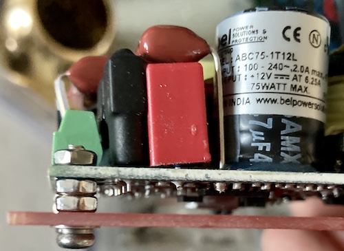
The AC-DC converter sub-board needs to be mounted to the PCB with electrically conductive standoffs (so that the ground is connected.) I used some cheap stainless M3 bolts and then double nutted them with a hearty dollop of blue Loctite #242 to make sure they wouldn’t come loose in the future. Originally, I planned on using my huge collection of standoffs, but the thread was incompatible. Whether that was just poorly machined nuts or some kind of SAE/metric mixup, I’m not sure. Either way, two nuts served as both decent vibration protection and a “good enough” riser to keep the bottom of the AC-DC PCB from touching the power supply PCB.
Cord Bore
For mounting the power cord (still permanently attached, to my mild chagrin) there was an included grommet that could be 3D-printed. I had a family member print it out using their DaVinci XYZ.
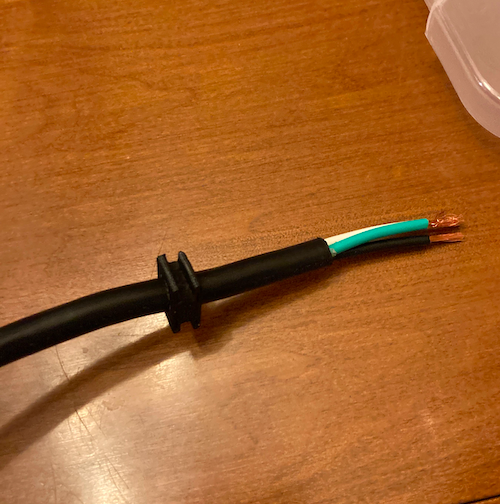
I needed a new 3-prong power cord for the new supply, so I swung by the hardware store and grabbed a replacement cord for a garburetor. This turned out to have maybe not been a great idea, because the insulation was so thick that the provided grommet was too narrow for the cord to pass through.
After several hours of complaining, about ten minutes of filing, and probably enough microplastic dust to cause a future ecological disaster, I had the grommet widened enough to fit the cord without significantly compromising its strength:
The fit was fairly tight, but I didn’t think this would work great as a strain-relief method. If someone like a cat, baby, or YouTuber tugged hard on the cord, it was still going to just slide right out. I decided I would try a “lamp cord knot,” or underwriter’s knot, which is apparently the UL-approved way of tying an electrical cord so it doesn’t come out.
I also had to file back a bit of the flash on the grommet just to get it to seat into the case, so it was a good thing I had already broken out the file.
Live, Neutral, Grounded
After measuring off about 15cm of cable, I cut back the power cord insulation and cut off the white and black wires, leaving enough to make the aforementioned underwriters’ knot and a short length of wire with which to reach the power switch. As for the black and white wire I cut off, I ran them from the power switch into the live and neutral inputs (respectively) on the PSU frame. I crimped a ring terminal onto the green “ground” wire after making sure the parts I had in my hoard were a good size for the “standoffs.”
Of course, I realized after I crimped on the terminal that I didn’t cut long enough white and black wires to comfortably reach from the converter to the power switch. After grumbling for awhile, I reached into my pile of 3-prong IEC power cords and cut up the sketchiest one I had (an 80s sunburned over-moulded cord with a seriously kinked strain relief close to the computer-side plug) to get some more black and white cable with safe insulation for wall power. That’ll fix it. Measure twice, cut once, blah blah.
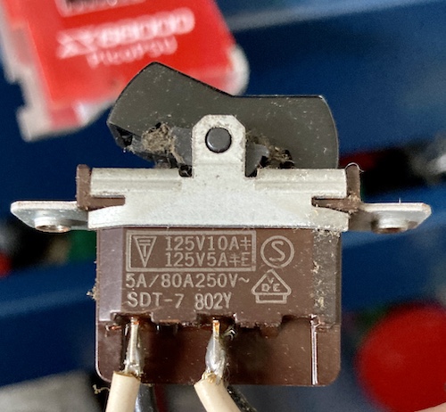
The original (and gross) Alps-branded power switch is rated as good for at least 125VAC, so it was fine to re-use it in this application. Desoldering the wires from the power switch went a lot easier than with the Bad ADB Mac LC, because the switch is burlier but mostly because I was a lot smarter about thermal management and snipped the wires off very close to the terminals so I could use a solder sucker to evacuate the “knots” without having to untie them using the hot tip. I thought about disassembling the switch to clean it, but it looked okay after picking out all the grit and dust using q-tips and toothpicks that the fan had pushed into it over the years.
While putting the power supply back together, I decided it would be a good idea to leave the monitor “pass-through” power outlet disconnected, as the decal on the backside of the case was now wrong (it’s no longer 100V.) According to the plastic on the connector, it’s rated for up to 125VAC, but I figured it would be best to remove the temptation entirely. I’ll probably 3D-print a block-off plate or something for the hole in the future, so that curious fingers can’t touch the exposed switch contacts inside the supply.
The J-spec “ground lug” on the case also makes me a little uneasy as well, as the ground on the AC/DC converter is not actually connected to the metal frame. Hopefully, nobody would actually use the ground lug now that they have a nice North American 3-prong outlet.
Putting the “low-voltage” harness together for the rest of the computer was cake itself. These big screw terminals were super pleasant to use compared to the tiny ones on the AC/DC converter itself, and they happily grabbed onto the varying gauges of wire and held them taut. It’s a little tight in there but everything seems to be fine:
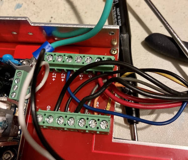
As you can see, I had extra pins left over. The PicoPSU has a special 4-pin connector on the top that is dedicated to providing drive power; reportedly, it is somehow more reliable at providing more current through these tiny pins than the thicker-gauge Molex ATX connector at the bottom.
I can’t confirm this folk knowledge either way. Low-level technical documentation on the PicoPSU is extremely lacking for what is supposed to be an enthusiast product, and the only mention of this connector in the so-called “datasheet” and manual is that it can be used when you’re adding more than one hard drive to a system. That said, it makes sense to me that if “real” ATX power supplies have dedicated connectors for drives instead of powering them off the main cable, it might be a good idea to do the same thing here too.
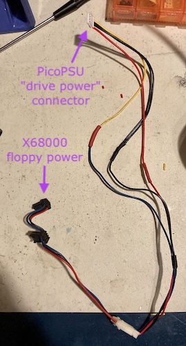
My revision of the X68000 PSU replacement board didn’t have a provision for this connector - a later one supposedly will - so the advice is to splice into the floppy harness. This way, the thirsty (and picky) floppy drives can get all the juice they need.
I spliced the original floppy harness into the 4-pin JST EH connector that came with the PicoPSU for drive power. I don’t really like doing splices, but this seemed mechanically strong and worked out fairly well. Unfortunately, on the original floppy cable the red (5V) line is much shorter than the 12V and GND lines, probably because the other two come from the “rear” of the original power supply. This meant that my harness looked kind of lopsided when I lined them up side by side. I’ll live with it for now, especially since this harness will spend most of its life tucked in behind a floppy bracket where I hopefully won’t have to see it again.
If I end up adding a SCSI hard drive later, I’ll probably be back in here splicing this cable again so I can re-add the Molex connector I just cut off. Although, SCSI2SDs are bus-powered…
One of the screws didn’t line up between the new PSU board and the original metal case. I had to sort of hog out the board (no copper in that area) and then nearly cross-thread the screw to get it started. I still feel kind of guilty about it.
Putting the case back together was a lot of work, too. Because I chose such a thick electrical cord for my supply, and added an underwriter’s knot, there was a lot of cable jiggling that had to take place down at the cord-and-switch end of the Tetris-piece that is the power supply. The green “ground” cable was especially bad, as it had to be positioned in a certain way so that the ring terminal would fit but it was also so thick as to impede putting the case halves together if it wasn’t perfectly arranged.
Eventually, I triumphed, and I got it all back together. Now it looks like the old power supply but with a three-prong power cord. That was a good way to spend a few weeks, fifteen minutes at a time.
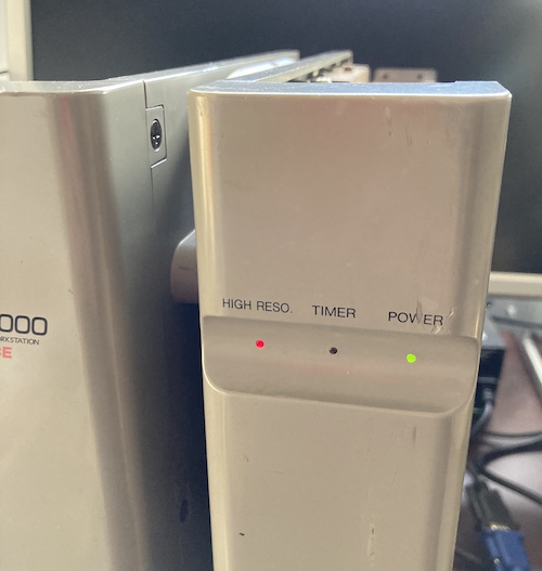
I tested the supply on the bench to make sure everything was working. When plugged in and switched on at the back, the supply immediately leapt to life, which made sense in retrospect as the on/off pin of the PicoPSU is pulled low on the board. All of the rails checked out fine - really happy that this works without a load - and it was ready to be reinstalled into the X68000.
And does it actually power up the X68000? You bet it does, although there’s still lots of work to come to repair the computer all the way…
Although it seems like not a lot of work (and I’m pretty sure most other people who built this supply got it done in a weekend) putting this power supply together took me a long time to do. I did learn a bunch about electrical safety, although I’m definitely not going to be signing up to work with wall voltage again any time soon.
That is, unless there’s a good deal on some more computers that need power supply work. But how likely is that to happen?
Repair Summary
| Fault | Remedy | Caveats |
|---|---|---|
| Someone said bad things about the power supply. | Replace it with a PicoPSU. | The original power supply might still be okay, after recapping. |