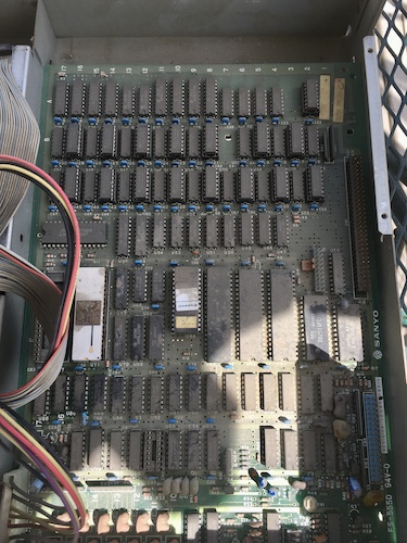
Sanyo Triple Five
Tags: computer sanyo mbc555 pickups homemade-hardware power-supply
Even though I seem to have terrible luck with x86-based computers, that doesn’t mean I have to take it lying down. I can go out there and cause even worse things to happen to me. Like, for instance, buying a broken super-budget PC-incompatible from 1982.
Sanyo made a bunch of interesting computers over the years, and the MBC-555 is no exception. It will run MS-DOS, but the 6845-related video chipset is completely incompatible with CGA – the Sanyo’s high-res mode is 8-colour bitplaned 640x200, like a PC-8801mkII! Reportedly, it is also slower than a 5150, and has a smorgasbord of weird hardware bugs that render it even more incompatible with common PC software.
If you want to get me onboard with your el-cheapo computer, one good way to do it is to make it really weird. As you might expect, not too many pieces of software were written to target this hardware specifically – the most notable game, for instance, appears to be a high-res port of the TRS-80 game Time Bandit.
As a result of all this combined weirdness, I’ve been on the hunt for one of these for a few years. Reportedly, they were a really popular computer when new, thanks to their low price, but I suspect a lot of them were simply binned after they became obsolete. I found this one on an eBay auction in Egypt, and paid the scalper price of one dollar.
Plus, like, a lot of shipping.
Since I knew I wanted an MBC-550 or -555, I had been scouring around for the keyboard and system. I managed to score the keyboard for $1. Then the seller listed the machine a day later, which I also got for a buck as previously mentioned.
Keeb Hoard
The keyboard arrived first, thanks to a surprise spring blizzard. It was at this point that I began to wonder if I had made a big mistake and paid money for a broken AT keyboard. However, it turns out the keyboard is indeed a little unusual for an IBM PC incompatible - it emits ASCII codes into a Mitsubishi M5L8251 USART.
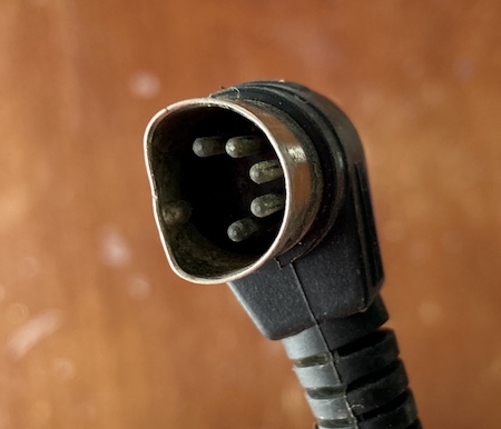
The keyboard did not enjoy its experience being shipped. Most of the damage seemed limited to the 5-pin DIN connector, whose shape was no longer round. A little bit of work with some pliers and test-fitting it into the back of the machine got this into “working” state, but it’s quite ugly.
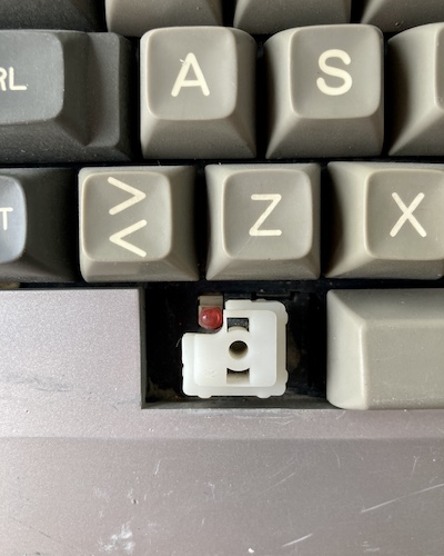
I figured that this missing key was either Graph or Caps Lock. The “Lock” keycap was there, but it’s on the right side of the keyboard, and all the pictures I could find of this keyboard elsewhere say that Graph is supposed to be on the right.
Supposedly under these keycaps is some kind of switch which is very desirable to keyboard collectors. I find that a little surprising, because the feel was terrible. Some keys were totally collapsed, and won’t pop back up, and one of the screws just spun in place when you try to undo it.
I took it apart to clean it, and was happy to find that the board looked fairly clean despite the massive piles of dust, hair, and miscellaneous gunk. Some epoxy stuck the broken-off screw post back on, but the broken and missing corner will need some more surgery – maybe a visit from the Bondo fairy.
In the near future, I’ll give this keyboard a full mechanical service, as it looks like it’s seen some real mileage. Hopefully these are like Alps switches, which coke up over the decades and need some lubrication to feel good again.
One bonus weird feature: the keyboard has a “RESET” button on the side. It really doesn’t seem like a good idea to put one there.
The Main Event
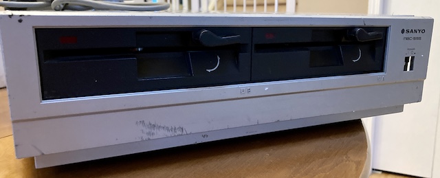
Eventually, the main machine arrived, so the keyboard got put aside. The main unit was in as bad or worse condition – part of its front fascia had broken clips and was just hanging off. The power button was long gone, and the whole machine was covered in a layer of stinky dirt.
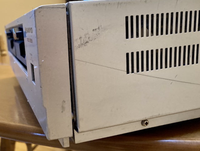
Even though the front fascia is silkscreened plastic, I was pleasantly surprised to find that the rest of the case was painted steel (a magnet stuck to it) – that will make it easier to strip and repaint in the future, for sure. Of course, it also means I have some dents to pound out. Looks almost like this computer was dragged against something.
The power switch got hammered too, with the little plastic rod that goes into the button broken off. Of course, that power button is long gone as well. A shame, as finding these Alps power switches (this one is an SDGA3P) is not cheap at all – eBay scalpers want $13 per!
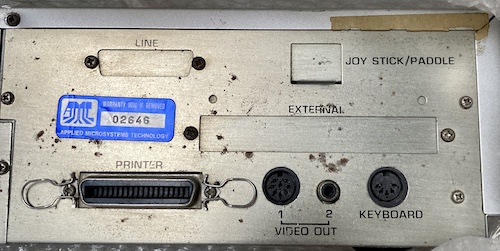
Around back, there’s a tag showing it as being an “AMT-555,” which must have been a regional sub-brand. That “AMT” stands for “Applied Microsystems Technology,” perhaps the vaguest corporate name ever. Google couldn’t turn up anything. Either way, this machine has serial number #02646. It’s anyone’s guess as to whether that means they actually sold 2,646 of them to whatever market this was for.
Update: A reader wrote in who has a personal connection to AMT. Their username on twitter is hamazz0:
Hi, saw your post on the “Sanyo Triple Five”, you mentioned “AMT” stands for “Applied Microsystems Technology,”, yes that is correct, the company belonged to a relative, they operated from the 1980s- late 1990s out of London, UK, at the time they had distribution rights with multiple suppliers, the one you got probably came from their Egypt Cairo Office which was the main distributor for Africa and Middle East. I estimate appox 500 or so were sold in that region during that period. They done alot of work at the time with the Egyptian government.
Some of the distributed machines were modified for voltage, others had memory piggy back chips to increase the ram, some others were overclocked for processor speed increase.
Thank you for writing in and giving us some historical context for this particular computer!
There are also some unpunched blanks for “LINE” (serial,) JOY STICK/PADDLE and EXTERNAL. There’s no slot that I can see for installing an expansion card in this – you’ll see for yourself soon enough – so I have to assume any expansions connected to the CN1 pin header on the motherboard, and were pigtailed onto this part of the case. Weird to us now, but not unusual for this era.
The printer port is a little unusual, as it’s neither your standard IBM PC Centronics DB25, nor is it a teeny-tiny Japanese printer port like on an MSX. I doubt I’ll be using it.
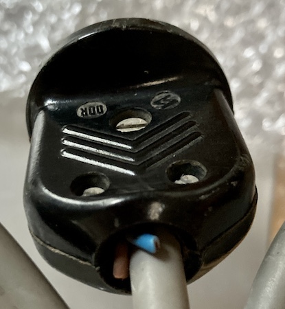
The power plug is a little weird – it looks like an Egyptian “Type-C” plug, but it has these very thin-gauge brown and blue wires sticking out of it that were unceremoniously severed. Made in the DDR! I am not really confident that this is an Egyptian-market machine, so much as it is likely European e-waste that has bounced around the world until it got scooped into however this one eBay seller sources his impressive inventory. Still, someone probably loved it, as evidenced by the attempt at case repair.
As you might have guessed, that means this is a 240V system. As soon as I opened the machine, I found out how the conversion was done.
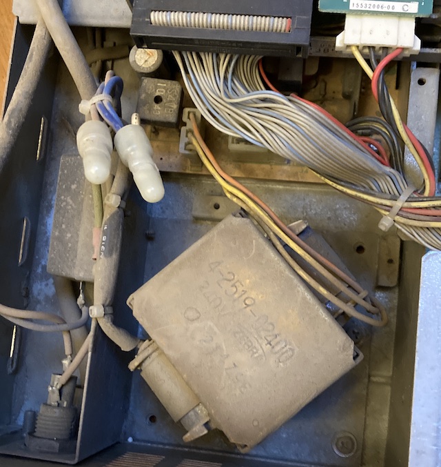
It appears to be one absolutely massive transformer, hooked into what I assume is the original secondary-side power supply board.
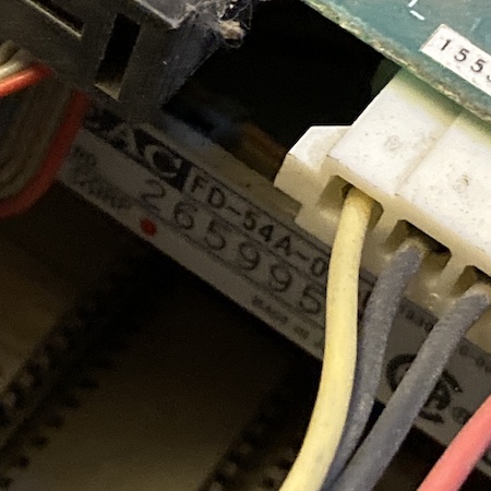
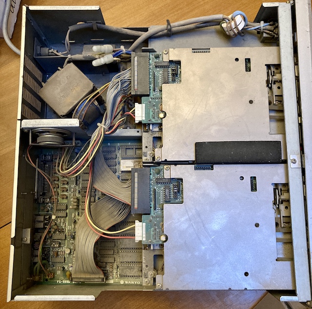
Floppy drives are some very nice-condition black (guess they couldn’t get silver) TEAC FD-54A 48-tpi (“single-density”) drives. They’re plugged with a thick layer of dust, as is literally everything else in this machine.
![]()
It’s quite impressive that this much crap was pulled into the computer. Where was this thing used?
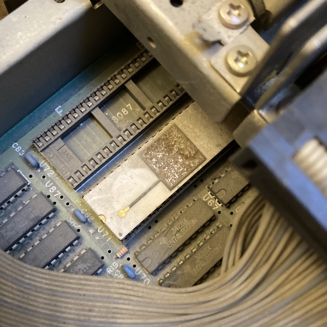
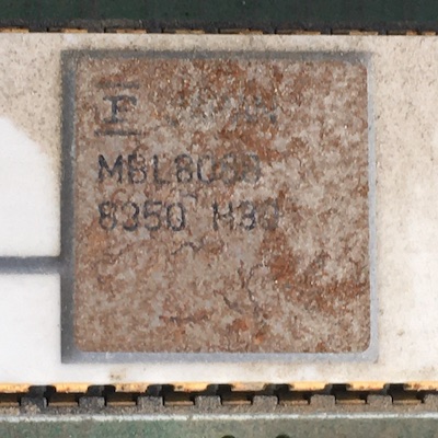
In the CPU slot is this ceramic package. The label is so oxidized that I couldn’t tell what it is, but other Sanyo MBC-550/555s have it as a plastic-package Intel 8088. How strange. The 8087 socket next door is unoccupied.
Yeah, I’m not touching this without giving it a scrub first.
Bath Time
One warm spring day, I decided it was time to take the machine apart, and blow all the dust out. My trusty XPower “Cyber Duster” (great tool, but such a bad name) did not do a great job blowing the dust out for once. Wherever this machine had been used had clearly combined the airborne dust with oil, leaving a thick film of clingy gunk that needed to be washed off.
Even though the floppy drives were absolutely filthy from the top, the underside was very clean. Too bad that doesn’t really matter to the function of the drive!
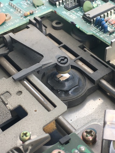
I gave the single head on each drive a thorough cleaning, and greased up all the moving parts with lithium spray grease. I do somewhat regret doing so, because it got everywhere. Definitely need to buy some sort of tube lithium grease in the future.
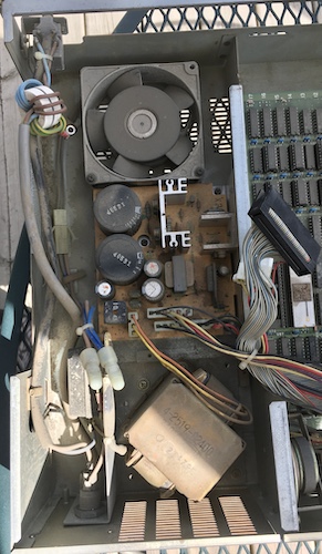
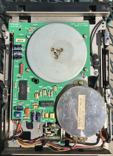
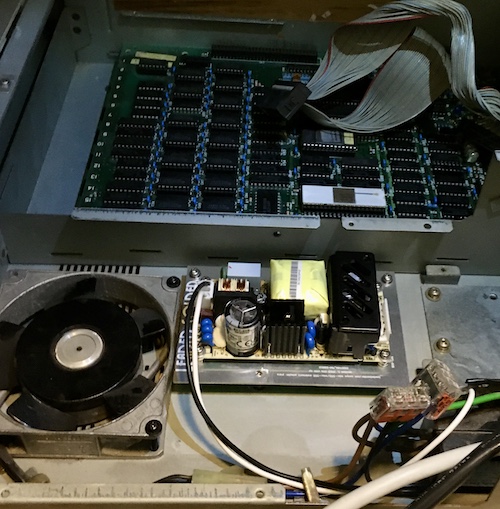
Once the floppy drives were removed, it was easy to get to the motherboard. I found another surprise under those drives: this Sanyo-branded AC cooling fan! For a budget computer, this seems like a very expensive part. It’s got a sand-cast aluminum frame, with the fan supported by ball bearings.
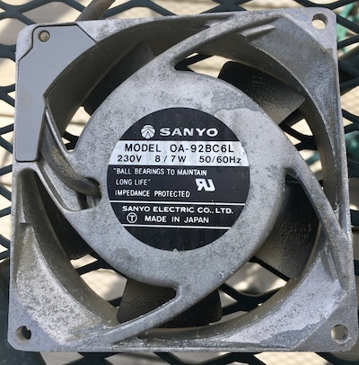
Even though it’s a 230VAC part, I decided that I would keep it. Even at half voltage, it would likely still do an okay job cooling. Unfortunately, it won’t be cooling the motherboard, as the machine’s case is split in half by a chunk of metal that impedes airflow. It’s possible that this fan is a hack offered to hotter countries in order to keep the (very, very linear) power supply cool and therefore reliable.
Once I separated the enormous and heavy 220V transformer from the rest of the wiring bundle, it was easy to pull everything out.
A lot of the RAM ICs are socketed. According to the manual, this was to facilitate a pair of 64kB RAM upgrades, so this machine should boast a total of 256kB. There are also memory boards that plug into the expansion connector at the right edge of the motherboard (the large black one in the picture above.) I’d sure like to upgrade the RAM even further and add other fun toys, but I haven’t been able to find the pinout for that connector yet. A serial port would be really nice to have.
I went ahead and dumped the socketed M5L2764A boot ROM. Although the TL866 software kept complaining that it was reporting an ID of $0000, bypassing this check allowed it to dump as a M2764A@DIP28. To make sure it wasn’t corrupt, I fed it into my “tile extractor” Python script to dump the 8x8 console font:
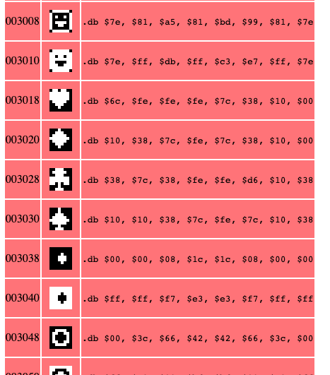
I checked, and this ROM is identical to the one floating around MAME already, but you never know if you have an older (or even newer!) version.
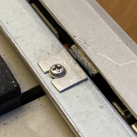
The motherboard was really weird: it seemed to be bolted only to the rear case, with two screws through the printer port, and one screw in the corner. What’s more, the motherboard didn’t lie flat on the little “shelf” of the case; it stuck up in the air. Although I can’t see it with my bare eyes, this case is probably significantly bent. There are some holes at the front of the motherboard that probably at one time were screwed to L-shaped mounting brackets, but those brackets are long gone.
I stuck the motherboard in the utility sink and gave it a thorough dose of clean water and dish soap while scrubbing off the grit with a boar hair brush. Most of the dirt washed off quickly, but there was a thick glob near the RAM that wouldn’t shift without some major elbow grease – probably falling out of the disk drive during use.
Once cleaned, it was possible to read the label of the CPU. It is indeed a Fujitsu-branded 8088 in a ceramic package. Very cool!
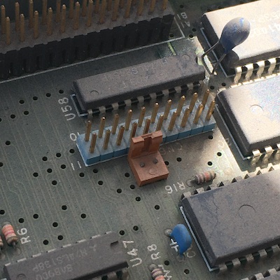
The speaker connector was fine, but this similar connector nearby had its pins broken off flush. I’m not sure what this is for, but hopefully I don’t end up needing it.
There’s also an empty DIP socket, which makes me a little uncomfortable. I had to wash the motherboard a few times, but it did come out fairly clean.
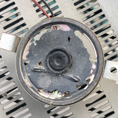
This Sanyo-branded speaker did not survive the last couple decades of life. Its cone is pretty shredded, and I don’t know how to repair speakers. It’s definitely old – the back of it says “R.O.K.,” for Republic of Korea – so it’s a shame that it didn’t make it. The magnet is still super strong, and kept sticking to every metal object nearby when I put it down somewhere. Are these things rebuildable? Might be time to learn a new skill.
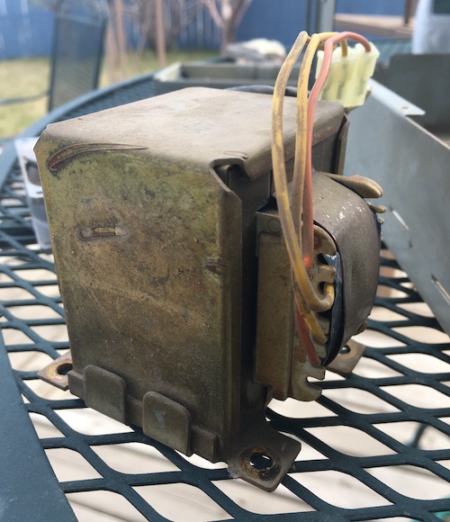
I hauled out the transformer, but I wasn’t able to determine anything useful just by staring at it. It’s easily the heaviest single component of this machine. I was hoping that I would be able to easily reconfigure it for 120VAC action, but the terminals (taps?) were all covered with spot-welded sheets of copper.
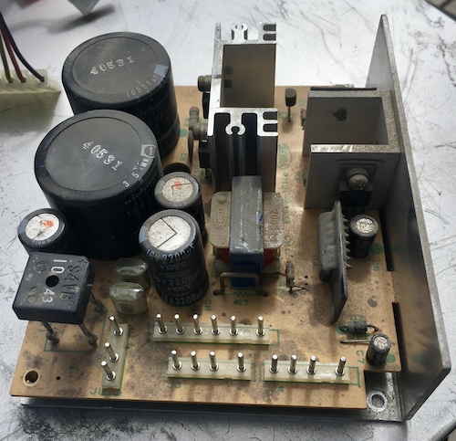
More expensive metalwork is on display in the heatsinks of the power supply. It’s been awhile since I’ve seen an entirely-linear power supply like this.
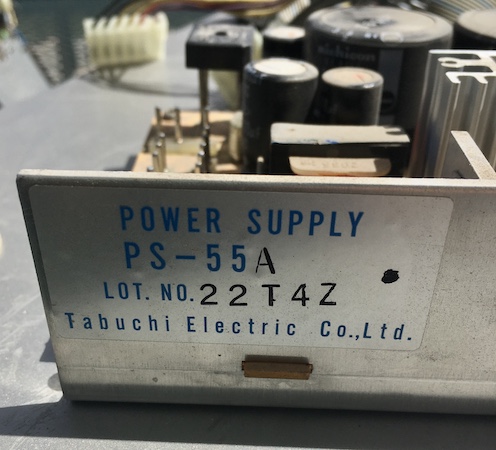
I did some quick searching, but could not figure out the input voltage for this board from the internet alone. Hopefully, all would become clear soon.
After splitting all the parts out, I washed the motherboard and all the major case components in the sink. It’s amazing how much grime came off. I wasn’t completely happy with how stained and oxidized the case had gotten, but it would be enough for now. What do you want for a buck?
I Meantwell
I went back and forth on whether to keep the original power supply.
It would have been a cool project to just swap out the transformer and have this thing up and running on 110V, but I had a lot of difficulty trying to find substitute transformers in a catalogue. A lot more research is needed. Rest assured I’ll be doing a transformer swap in the future on a different thing, though…
I’d used a Meanwell RPT-60B power supply in another repair project of roughly the same era, and although that project hasn’t gone well so far (to say the least,) I did like the power supply. This inexpensive supply is super tiny at 4 inches x 2 inches, and provides +5V, +12V, and -12V, which is exactly what we need for this little Sanyo. The rated current is a bit wimpy, but let’s be honest: so is this computer.
In order to securely install the Meanwell supply, I had to figure out a way to mount the 4x2 circuit board inside the computer’s steel case. The original power supply was mounted to an L-shaped bracket under the floppy drives, which in turn was screwed directly into threaded holes in the bottom of the case, using M3 screws. I decided to keep the case as original as possible, rather than drill more holes into it.
Normally, I would just make an adapter plate out of some old scrap steel I had lying around, but this time I decided to get a little fancy. Another hobbyist had tipped me off that JLCPCB had a really good price on aluminum PCBs. So good, in fact, that he was using JLCPCB as a sort of fancy CNC, to cut out expansion card brackets.
I whipped up a quick adapter, printed it out, and placed it on the underside of the old supply to check. I thought I did a pretty accurate measurement, so I then sent it away. Indeed, it was even cheaper than a fibreglass (FR4) PCB… by 25 cents for five “boards.” To hedge my bets – and to re-use the leftover four boards if the first draft did actually work through divine grace – I also jabbed a bunch of proto area holes onto the board.
The quality of the cut and holes seem very high, and the green solder mask is definitely adhered, but the silkscreen on the bare side flakes off very easily. One of mine lost almost all its silkscreen just from being taken out of the shrink wrap. Not sure I would do this again, unless it was for a very specific purpose. Maybe it would be good for something like a PC motherboard port cover, or an especially weird bracket?
Two of the mounting holes lined up perfectly, but the third one didn’t. Oops. I did not check thoroughly enough, I guess, but two holes would be more than enough, assuming that the Meanwell lined up too.
Since it’s nice, soft aluminum, it should have also been pretty easy to drill a new hole to make it fit – but it wasn’t. Even with a centre punch to set things up, my drill bit walked all over the board and wouldn’t drill very well. Hey, wasn’t the whole point of making this damn adapter plate to avoid having to drill things? Two out of three mounting holes would have to do – I stuck a spacer underneath in the “third” screw hole to make sure the not-so-good adapter plate wouldn’t wobble.
Not to change the subject, but, this is the part where I found out that the RPT-60B power supply was on mega-backorder. There were two left at Mouser, but by the time I filled my cart up enough to get free shipping, there were zero left. Hard to do a power supply conversion with no power supply. I stuck one on backorder at Digi-Key and put the whole project aside for awhile.
Eventually, one arrived, which meant it was time to complete the wiring harness.
Harnessing the Power
The old wall cord slid out once the jam nut for it was released from the grommet. It was wrapped around a ferrite ring, so I ended up clipping it again in order to loosen it enough to pull it through the back of the machine.
I took the clipped-off portions of the wire and laid them out flat, in order to figure out how much more of the wall cord’s jacket I’d have to remove in order to have enough wire to wrap around the ring. It turned out to be a lot more than I initially thought, but there was still lots of cord left once I was done winding the new conductors through the ferrite ring.
Getting the old chunks of live/neutral off of the power switch was an ordeal, not least because I was lying on the floor. I should have done the right thing and removed the entire assembly from the machine before attempting to desolder. With some patience and tactical clipping, everything came loose without me even melting the switch this time.
The original wiring scheme in the machine was brown/blue, which appears to be the way that Europe does things. I was not able to figure out what the wiring scheme for Egypt was, so I decided that this computer was probably a European conversion. In a European scheme, brown is live, and blue is neutral, so I soldered the black and white wires from the power cord onto these respectively. Green got crimped up with a ring terminal, so that it would still serve as chassis ground.
To connect the switched side of the harness to the fan and the Meanwell at the same time, I used 3-way Wago 221 lever nuts. I had bought a set of these fancy things on impulse and they were finally paying off. They’re not that much bigger than an old-school wire nut, and a lot less finger-pokey and frustrating than those wire nuts. You should consider them if you’re doing any home wiring or dumb bodge jobs like this. Wago, please send me money for this plug.
Get it? Plug?
Before connecting the wall power to the Meanwell, I decided to do a quick test run.
The goals of that test are simple:
- Pushing the power switch should turn on/off the AC cooling fan;
- And nothing should electrocute me.
Because you’re reading this, you can predict that #2 at least was successful. Everything went well. I was actually a little surprised by how quiet the giant old fan was, but I guess running it at half voltage helps.
Satisfied, I crimped up a simple live/neutral harness for the Meanwell using my JST VH crimper, and then connected it to the Wagos. We now had power flowing all the way from the wall, into the computer, and into the Meanwell power supply and the AC cooling fan. Pretty cool! Now just to make it actually power, you know, the computer parts.
Output was more of a challenge. Although the JST VH pins are quite generously sized, there are a lot of thick wires for each voltage in this machine. There’s only one pin on the Meanwell for +12V, but I thought four wires needed to go into it – one for each floppy drive, and two beefy ones going to the motherboard. And it’s just as bad for grounds: six grounds (two motherboard, two each on floppy drives) into two pins.
Without the disk drives, this would be an easy 1:1 conversion. With the disk drives, well…
From previous experience with this exact problem, I knew that trying to fit two 22-ish-gauge wires into a single JST VH pin was already going to be a struggle, much less four. So I decided to be lazy and use Wagos again.
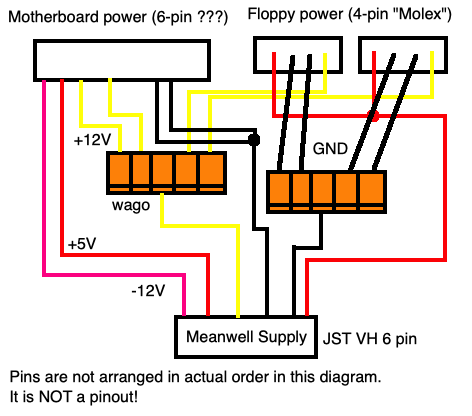
I crimped up one brand new 18-gauge wire, plugged that into the JST VH housing, and then used Wagos to distribute that +12V to the consumers. The four grounds of the floppy drives got their own 5-way Wago in the same way.
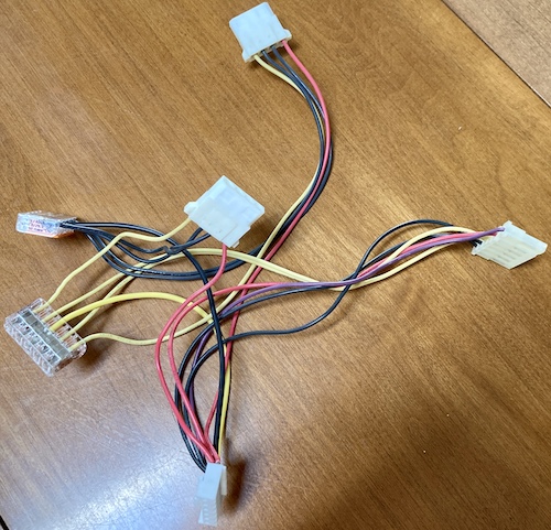
It’s ugly as hell, and very clunky: the wire nuts are bigger than the connectors the wires are going into. I am not proud of it. But it will work. If I want to pretty it up later, I can splice all these wires together into one bundle, and then solder and heat-shrink it all.
Uh Oh
Just as I was about to plug everything in, I noticed that the power supply connector on the motherboard had some silkscreen.
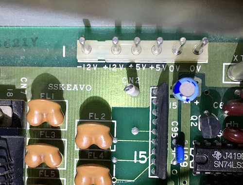
Wait a minute… two +5Vs? I thought it was weird before that the motherboard would need two yellow +12V wires and only one red +5V wire. It seemed that the definition of yellow and red wires were completely reversed! After inspecting the floppy power cables, I found that they also used red for +12V.
Once again, we have found another computer that doesn’t follow the red/yellow colour code. This is why you always gotta check! Although I wish I had checked before I did all the crimping, I’m very glad I didn’t try to turn the computer on with the wiring harness all mixed up – feeding +12V into +5V logic would make a lot of extra work for me.
After depinning and flipping the harness around in a considerably ugly way, I got ready to reassemble and test the computer.
Get Rideo of No Video
Through some kind of absolute miracle, the Sanyo MBC-550/-555 has the same video pinout as the PC-8801mkII. That means I can reuse my existing digital-RGB adapter once again. It’s always nice to have a project where I don’t have to solder a DIN.
There’s also a composite output, owing to the era, but I likely won’t use that.
After buttoning up everything on the inside of the machine, I plugged in the video cable and prepared to give the computer its first test flight. Because this is an interlaced 640x200 signal, I figured it was likely 15kHz and so wouldn’t be supported by the Samsung monitor I had lying nearby when I fired it up. And I was right: that monitor complained that it was in a non-optimal resolution called “???” and suggested I switch the computer to 1280x1024 instead.
I thought about moving the machine to another room to use a 15kHz-compatible monitor, but then I remembered the GBS-Control upscaler that I built awhile ago was still attached to the supergun in the next room. That upscaler was much easier to move than a whole monitor, and soon I had wired the whole mess up.
Unfortunately, although the GBS latched onto sync immediately, I didn’t get any usable video. The primary floppy drive was spinning – and making quite the racket, as the spindle sounded rusty and nasty for the first few minutes, until it seemed to smooth out whatever it was dragging on – but the best the GBS could wring out of it is this bizarre staircase pattern. It’s sort of a cool glitch art artifact.
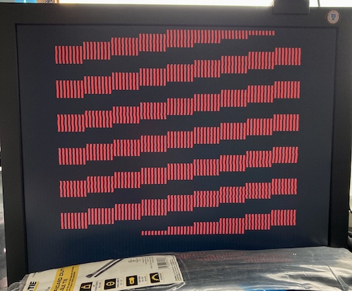
After checking YouTube to see if this was indicative of a defect, it appeared that the MBC-555 simply had no video output until you stuck a disk in it. This makes sense, since the “BIOS” ROM is really just a primitive bootloader that is trying to get the floppy-drive controller to load the rest of the BIOS into RAM1. Presumably, that “rest of the BIOS” must include the video logic.
I assumed that the GBS was simply hallucinating something from line noise, and went on with my life. How wrong I was.
Making a Boot Disk
Luckily, I was able to find some pretty good-quality dumps of many Sanyo disks at the Eris Creations website. It is very cool that someone spent the effort to back up all these disks, and it appears that the copy-protected disks were even dumped in a way that they may be able to work if written directly by a Greaseweazle or other laissez-faire floppy drive controller.
However, the site only had Sanyo DOS 1.25, and I knew there was at least a version of MS-DOS 2.x available for the system. With a quick web search, I also located a copy of MS-DOS 2.11 for the Sanyo MBC-550 at WinWorldPC. Imagine my confusion when I found out that the image was 360K, which implied that it was double-sided.
This was the point where I found out that there were more Sanyo MBC-55x models than I originally thought. Mine is clearly an MBC-555, equipped with dual Teac FD-54A single-sided floppy drives, but there were two successor models: MBC-555-2, which had 360K (presumably double-sided) drives, and MBC-555-3, with a staggering 720K.
A little disappointed, I wrote a copy of lame old single-sided Sanyo DOS 1.25 to a floppy disk using the Sanyo’s primary drive and a Greaseweazle. I’m not sure if it’s possible to upgrade to a double-sided floppy drive, or even desirable, since it would be a shame to lose the charm of the black Teacs. Maybe I can bang a Gotek into this later for a test.
The rusty old floppy drive gave me some hassle, mostly in that it didn’t want to release the disk carriage fully unless I gave it a quick jerk with the eject handle. Because of my crappy greasing job, it also got lithium grease all over the floppy substrate. So there’s a little more rebuilding work to do there, which is fine, because…
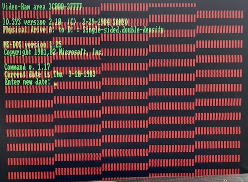
…it booted! Although the video is pretty jiggly coming out of the GBS upscaler, it’s very readable. You can also see that the red staircase pattern hasn’t gone away, which makes me think something might be wrong with the RAM that represents the red bitplane. But the computer has successfully loaded its BIOS from floppy disk, and then booted DOS 1.25!
Inconclusively Concluded
After some serious work, the Sanyo has gotten a modern power supply, and is booting from floppy disks, but there’s still a long way to go.
In the next chapters of this project, I’ll be repairing the keyboard, re-servicing the floppy drives, re-epoxying the case, making a new power button, fixing whatever is going on with the video, and maybe even eventually playing a pirate copy of Time Bandit.
-
Sure sounds a lot like how many CP/M machines boot, doesn’t it? Not that I’m trying to imply anything about the development process of this extremely strange computer, or anything. ↩