The Origin of the Species
Tags: computer nec pc8001 pickups homemade-hardware floppy
NEC moved into personal computing relatively quickly. After the hobbyist and industrial success of the TK-80, they produced a handful of “better TK-80s,” which didn’t do as well as the original. Ultimately, they developed a whole new system: the 1979 NEC PC-8001. And boy, did they ever nail it.
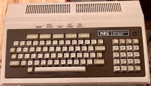
This machine came from Yahoo! Auctions Japan, and I got into a bit of a bidding war over it but ultimately paid ¥2600 (with surprisingly expensive domestic shipping: I probably fell into a trap there.) I was very pleased to discover that the computer was in such nice condition, as the pictures were poorly lit. Having never used a PC-8001 in person, I was also surprised that the bottom of the case is powder-coated steel and not plastic. Luxury.
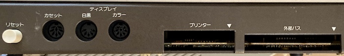
Around back, the PC-8001 has a generous helping of ports, but there’s never quite enough. You’ve got a reset button, cassette input/output/remote, and monochrome and colour video. There are also some male 0.1” edge connectors for printer and expansion bus. Those expansion edges look a little worn and oxidized, but it’s nothing I haven’t seen before. We’ll get to use the expansion connector later in this article.
Open It!
Since the back of the PC-8001 is somewhat open – you can see all the guts from the holes for the edge connectors – I decided that it would be a good idea to look inside for spider nests, exploded components, and the usual kind of crap that falls into a computer when it’s been in storage for a long time. I was pleased to find that the thick case also has nice threaded inserts to hold the screws in, although they needed a lot of force to get loose.
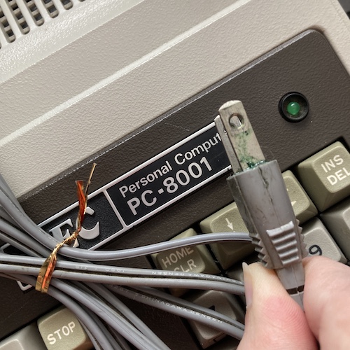
I also found this gross blue-green slime coming out of the plastic part of the power plug. I’ve seen this before on other power cords, as well. It looks like the same corroded copper slime that was on the Pyuuta’s AV cables, and makes me suspect that the plasticizer of the cord is failing and becoming corrosive. I’ve also seen it in the past with original-recipe NEC PC-6001s, so chances are it affects every cord made by that supplier in this era. I cleaned that gunk off as best I could with a shop towel and alcohol. If this machine gets a lot of use, I will likely replace the cord and maybe even treat it to a Meanwell or USB-C supply: any corrosion is really not a great idea when dealing with mains power.
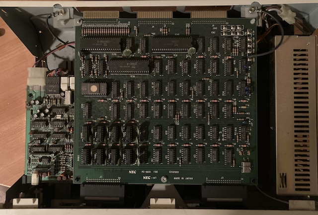
The overall layout of the PC-8001 is pretty simple. Owing to its age, there are no custom chips. In fact, the entire schematic was reverse-engineered by I/O magazine, so if you’re feeling jealous seeing those pictures, go make your own! I can’t do all the cloning around here.
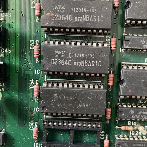
These µPD2364 mask ROMs contain N-BASIC. I noticed that MAME was complaining of not having a clean dump of these ROMs, so I will have to remove these and dump them in the future. There’s also an empty socket, presumably for things like an N80-BASIC extension ROM.
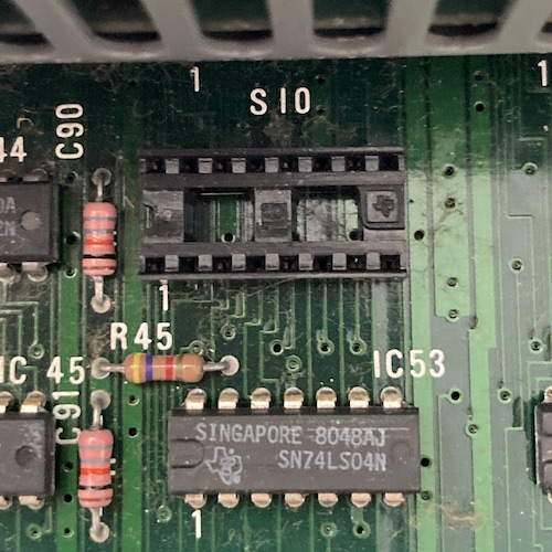
This “SIO” socket is meant to be for a serial connection1. Much like the later PC-6001’s internal RS232 header, this will let the enterprising hobbyist add an RS232 interface to the computer. Its pinout is reportedly documented in the owner’s manual, which I don’t have, but I’m sure it’s been replicated somewhere out there. I have been able to find the PC-8001mkII manual, but that is not very helpful for this specific issue, because the PC-8001mkII has a more conventional 25-pin serial port on the back.
There’s also a little 1x6 female header here, CN8, that appears to have its outer pins jumped. Checking blog friend Curt J. Sampson’s notes on the PC-8001 shows that this is for controlling the RS232 baud rate. A 1-6 strap has configured the computer for 300 baud.
Hue Will Regret This
After checking the aforementioned PC-8001mkII manual, I was able to figure out that the pinout of the digital RGB “colour” port on the back of the PC-8001 was likely the same pinout as the PC-8801mkII colour video adapter that’s worked on a whole bunch of other computers by now. That’s great, because I hate making cables.
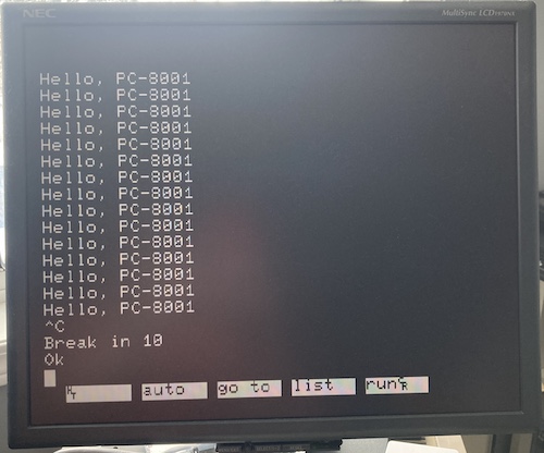
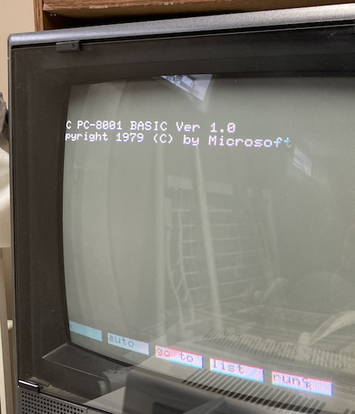
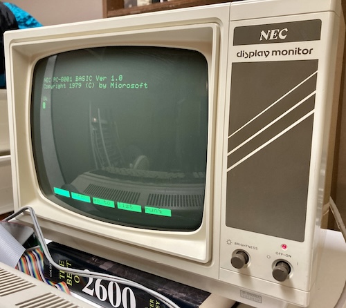
I hooked it up, plugged the PC-8001 into my 100V stepdown transformer, and flicked the power switch. My NEC 1970NX monitor leapt to life and displayed the 1979 copyright of NEC PC-8001 BASIC. Great! And the keyboard even worked properly.
There was just one thing left to do: get a glorious colour display.
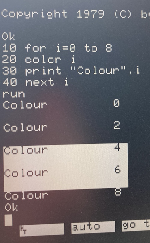
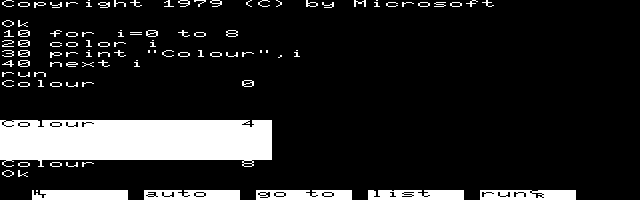
Hey. Where’s my colours? It appeared that the PC-8001 was treating the 3-bit values sent to COLOR as if I had a black-and-white composite monitor attached. Anything with bit 2 set was flashing, and anything with bit 0 set was invisible. I figured that I was in the wrong screen mode, and set about researching exactly what I needed to do to get my pretty eight-colour RGB back.
Just to be sure that it wasn’t a hardware fault, I also checked the behaviour in the MAME emulator. Fortunately, it was identical. Not knowing how to use something is a lot better than not knowing how to fix something!
Eventually, I asked Curt and he pointed me to a different document that was all about N80-BASIC in general. This one contained documentation on the command CONSOLE, which sets the console parameters of the system. Some of them are really sophisticated, being able to set stuff like non-scrolling areas. One of those parameters is “mono/colour.”
I entered CONSOLE ,,,1 and…
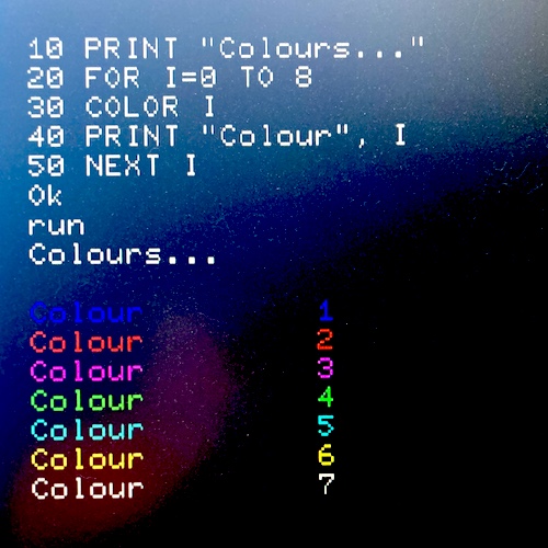
Colour! I also noticed a little bit of colour interference bars appearing that weren’t there before the mode switched.
As far as I could tell, the computer was working okay. Now we just needed to find something to load up on the PC-8001.
And this is where it became a genuine project.
Loading Software
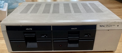
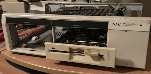
Although most PC-8001 software came on tape cassette, there was also a floppy disk drive made available. NEC made a dual drive unit, the PC-8031, available pretty early in the PC-8001’s life, although I’m not sure exactly when. It went through a couple updates, with one of the revised later drives being named the NEC PC-80S31.
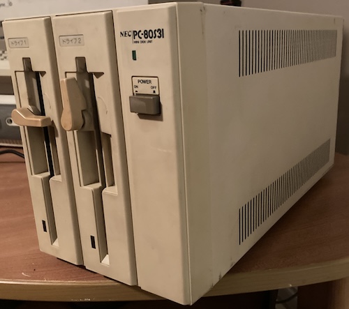
I managed to score one for about thirty dollars, which is less than I expected to pay, although I’m told that they used to go for under ten bucks and prices have been on a slow rise. Presumably, the “S” stands for smaller.
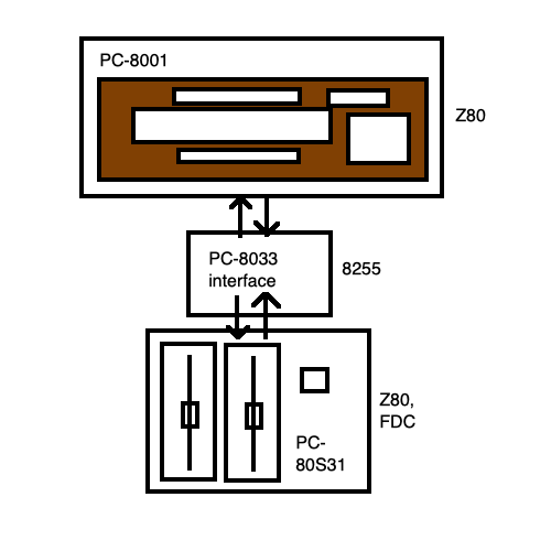
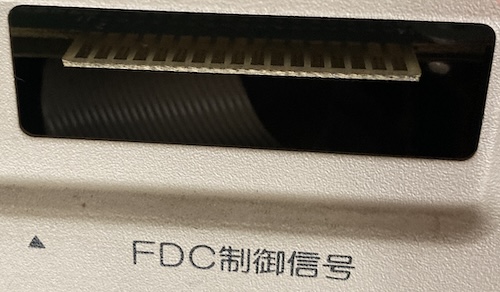
As you can see from the above picture of the PC-8001’s ports, the computer doesn’t feature a dedicated floppy drive port. Instead, there’s a device called the “PC-8033” which interposes between the expansion-bus connector on the back of the PC-8001, and the floppy drive connector on the PC-80S31. This device is frequently lost, and it costs more than both the PC-8001 computer and the PC-80S31 disk unit combined2.
Even if I wanted to pay a lot of money, no adapters came up on Yahoo! Auctions for a few weeks while I was looking. Luckily for me, there is some scattered documentation on how the PC-8033 works, so we can build a clone.
At the highest level, it puts an Intel 8255-compatible peripheral interface on the PC-8001’s bus. The PC-8001 talks through it to another Z80 inside the PC-80S31, which is responsible for doing all the disk-drive-like tasks. For this reason, this connection is referred to in the community as the “smart” floppy drive port3.
This logic-based isolation is a similar model to how the PC-6001 floppy disk drives like the PC-60314 worked. In fact, I can use the PC-80S31 on the PC-6001, as well as on my FM-7 and FM-8: as long as you can speak the protocol to the Z80 inside the drive5, it will happily read disks for whoever is asking.
Clone Zone
There was some interest from others on the VCF forums in cloning this piece. It looked like it had already been cloned in Japan in the preceding blog posts, but I couldn’t find either a schematic or a copy of the board to buy for myself, leaving me to make my own version of the 8033.
I ended up cobbling together some information from a blog page by Ryo Mukai, which in turn cited a helpful schematic of the PC-8001 to i8255-side interface, and also information about the i8255-to-8031 interface, i8255-to-80s31, and the PC-8001 expansion bus connector’s behaviour. Thank you for the help, Mukai-san and all the others cited.
One really confusing thing about this whole design is that NEC kept changing the interface on the floppy drive side, both physically and electrically. And there’s a lot of part numbers:
| Drive | Connector | Number of pins |
|---|---|---|
| PC-8031 | Edge connector | 34 |
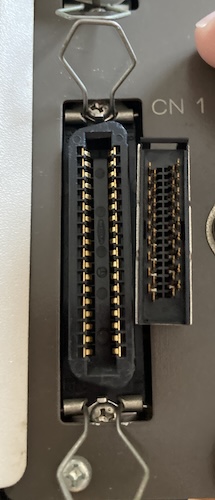
| PC-80S31 | DDK 57-series (“Centronics”) connector | 36 |
| PC-80S31K | DDK 57-series (“Centronics”) connector | 36 |
| PC-80S32 | DDK 57-series (“Centronics”) connector | 36 |
I was confused at what the difference between the 80S31 and the 80S32 was. It has the same connector, but the pinout is totally different. The same drive was sold in the same catalogues, for the same price, but the 80S32 was mentioned as “for expansion.”
Eventually, I asked CDP, and he said that the 80S32 was meant to be daisy-chained into the floppy port on the back of the 80S31. For expansion. Because of the altered pinout and drive-select behaviour, you can also connect it to the back of a PC-8801mkII that already has two floppy drives without causing conflicts. We need to update our diagram from before to include this new fact:
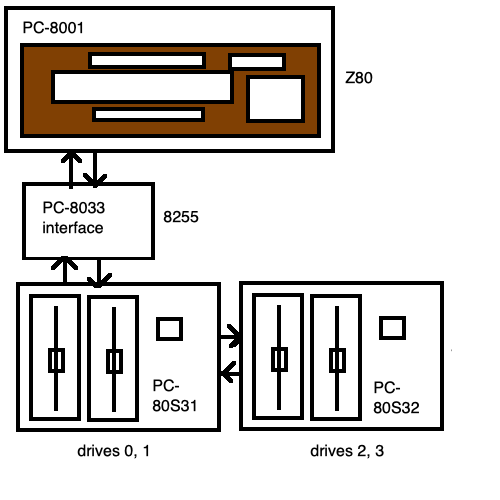
Wow, that’s a lot of stuff hanging off the back of this poor computer.
The important thing to take away from this is that if I wanted to support both my 80S31 and an original 8031, I would have to provide connections for both the 34-pin and 36-pin floppy. After squinting at pictures of the reproduced PC-8033, they have a 36-pin connector, but also call out “pin 34” specially.
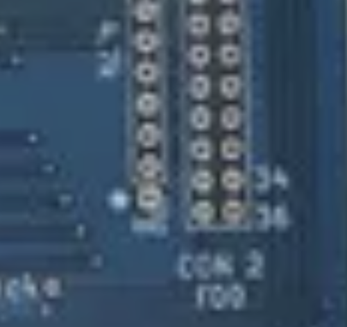
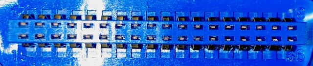
So what’s the difference between the 34 and 36 pin connectors’ pinout? We know based on this PC-8033 reproduction that there is only one more row - it’s a 2x18 instead of a 2x17 IDC connector. And indeed, the top 2x17 pins of each are the exact same.
| Row | 8031 A | 8031 B | 80s31 A | 80s31 B |
|---|---|---|---|---|
| 1 | PB0 | PA0 | PB0 | PA0 |
| 2 | PB1 | PA1 | PB1 | PA1 |
| 3 | PB2 | PA2 | PB2 | PA2 |
| 4 | PB3 | PA3 | PB3 | PA3 |
| 5 | PB4 | PA4 | PB4 | PA4 |
| 6 | PB5 | PA5 | PB5 | PA5 |
| 7 | PB6 | PA6 | PB6 | PA6 |
| 8 | PB7 | PA7 | PB7 | PA7 |
| 9 | GND | PC4 | GND | PC4 |
| 10 | GND | PC5 | GND | PC5 |
| 11 | GND | PC6 | GND | PC6 |
| 12 | GND | PC7 | GND | PC7 |
| 13 | GND | PC0 | GND | PC0 |
| 14 | GND | PC1 | GND | PC1 |
| 15 | GND | PC2 | GND | PC2 |
| 16 | GND | PC3 | GND | PC3 |
| 17 | GND | GND | ||
| 18 | x | x | GND | GND |
(All names shown are the pins on the computer-side 8255, not the floppy drive side.)
So: the additional row is just grounds to support the use of a 36-pin Centronics connector, rather than a 34-pin, which doesn’t seem to exist. Like with many things in this project, it was annoying to figure out, but easy enough to add.
On a similar note, there was a cryptic mention that the signal was important, and I had to go looking to figure out what it is that signal did. It turns out that this active-low signal tells the PC-8001 that a floppy drive or similar expansion device is connected. Enri, the same helpful person who gave SG-1000 and Pyuuta schematics freely, also provides a lot of PC-8001 data including the info on EXTON and a useful page about the 80S31 interface to add more context. Thank you Enri!
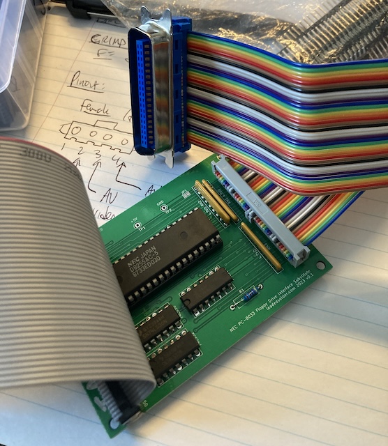
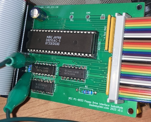
Constructing the initial version of the 8033 interface was pretty easy. I already had a scrap board with an 8255 on hand, so the hardest part of sourcing components to put this project together was finding an appropriate IDC connector to crimp up to the expansion edges on the PC-8001. One of my guilty pleasures about copying other peoples’ boards is that I can just duplicate their orientation and rough positioning of their ICs, which both makes routing easier and sometimes exposes little tricks they pulled to make their own routing easier. One such example is the discontinuous break between PC4..7 and PC0..3 up above – it makes routing to the floppy edge from the PC pins on the south end of the 8255 way easier. When this happens, it’s like getting a gift from the original designers. Or maybe I’m just weird.
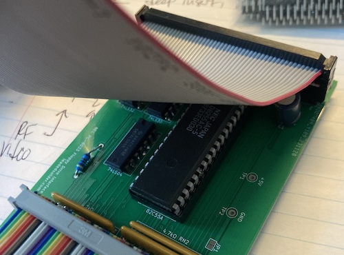
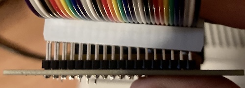
Unfortunately, I also put the 50-pin header onto the board backward, so the ribbon cable had to go into and then back out of the board, which is a little awkward. This was one of those things I couldn’t have figured out unless I had the cable in hand. I used a pre-made 50-pin 0.1” ribbon cable that I found on Amazon, and then cut one of the pin-header ends on and crimped on a card-edge header that I also got from Amazon. Unsurprisingly, fixing the board in version-2 so that the connector now pointed the right way made the routing way easier! There’s that “gift from the original designers” again.
It wouldn’t be one of my projects if I didn’t make one silly mistake. This time, that silly mistake was me ordering an IDC 36-pin connector that was simply too small for the 80S31! I’ll have to come up with some other project to use these with in the future.
Centronics IDC connectors are not super common on Digi-Key anymore, despite having been used a lot over the years. AliExpress still has tons, which is where I should’ve gone in the first place. I ended up buying three for about $14 Canadian, which is a reasonable price, and the quality seems good.
Now that I had most of the drive interface assembled, I still needed a disk to load. I went poking around the Neo-Kobe PC-8001 archive to look for software. What I expected was to find one or two generic “Disk BASIC” disk images, but what I found were different disk images meant for different drives and systems.
My options were named as follows:
- [OS] N80 BASIC system disk (PC-8001mkII)
- [OS] N80SR BASIC system disk (PC-8037SR) (PC-8001mkIISR)
- [OS] N BASIC system disk (PC-8034-2W) (PC-8001)
I decided to pick choice number 3, because I have neither a mkII nor am I lucky enough to have an 80SR. Keep it simple! I wrote it to a disk using a PC-8801mkIISR disk drive and a Greaseweazle.
It turned out, when I was doing some research later, that PC-8034-2W is the NEC part number for the Disk BASIC floppy itself.
Running It
Setting up this system for execution is not insubstantial. All the pieces are huge, so I ended up reorganizing a sewing table just to have enough depth. For looks, I wanted to use the nice NEC JB-1260M(A) monitor that I fixed in a previous entry.
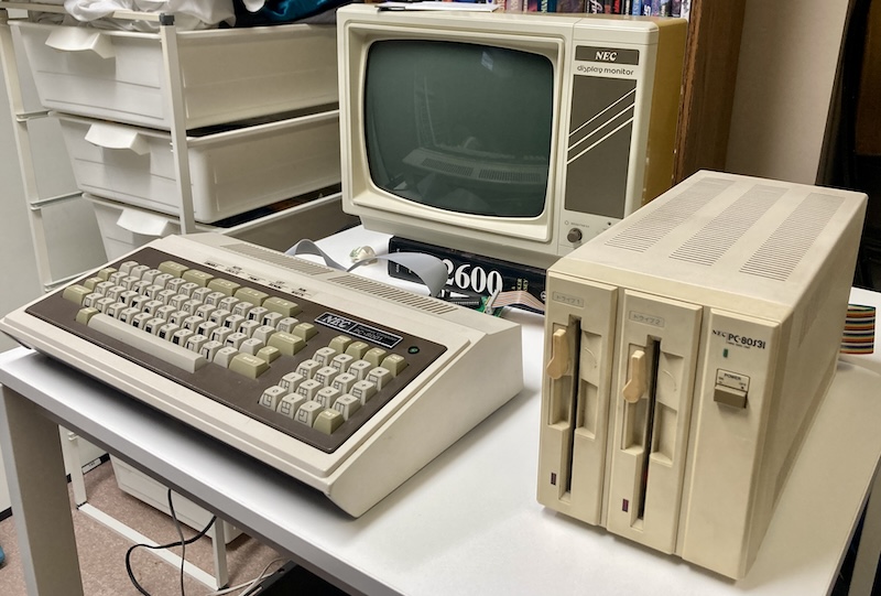
Looks cool, huh? Too bad it didn’t work out. After a while of searching, I could not find the monochrome composite video cable that I made for my PC-8801mkII way back when, nor could I find more DIN plugs to quickly make another one with.
Instead, I ended up using the NEC PC-TV151 monitor I got working awhile ago. This monitor has some significant downsides: mostly the fact that the image is super far to the left, as it was with the PC-6601SR in 66SR-BASIC mode (the convergence isn’t great, either, sigh.)
I will certainly need to do more work on this monitor’s front-end in the future, but for now I could at least use it to try and run NEC Disk BASIC.
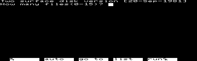
On my first test, I connected up the “8033” clone adapter I had made, powered the disk drive on, inserted the PC-8034-2W N-BASIC disk I had made on the Greaseweazle, and powered on the computer. The disk drive didn’t do anything, and an inquisitive attempt to run the MOUNT 1 command lectured me that it was a “Disk BASIC feature.”
I had expected this thing to attempt to autoboot: after all, we saw in the previous step that the PC-80S31 disk drive has its own ROM. A quick check with MAME showed that the PC-8001 will, indeed, attempt to autoboot an nbasicsy disk image (the same image I had just written.)
A reasonable person would conclude that something was wrong with my adapter.
Bodge Podge
To diagnose, I started with the basics. To confirm my pinout was right, I checked for +5V and ground, and found those. From there, I used the logic probe to see that the combined and signals, synthesized on my board, were working. The basics were present.
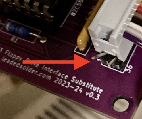
I threw the board on the scope, and found that the line on the 8255 was never getting toggled low. Doing a little more poking around, I also figured out that the line, which tells the PC-8001 a floppy drive is attached, was floating around 2.52-2.70V (noisy!) on the signal side of the pull-down, which does not feel active-low to me. I had pulled it down with a 4.7kΩ resistor, but that seems to have been insufficient.
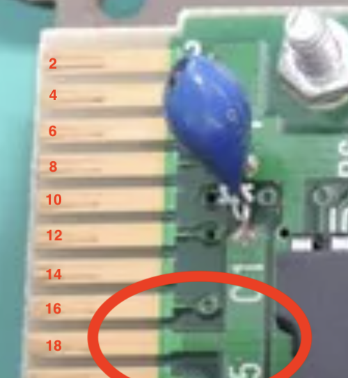
Clearly, I made a mistake in trying to “play it safe” with a current-limiting pull-down resistor6. The original PC-8033 board clearly shorts pin 18, , directly to the ground pour. Beefy! I went to the I/O Magazine PC-8001 schematic to figure out what is pulling up on the other side.
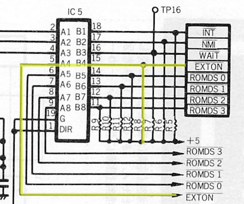
The resistor R7 on the PC-8001’s motherboard pulls it up. Unfortunately, the I/O Magazine schematic I was working from didn’t bother to list the exact value of R7, but based on the voltage I was seeing, we can probably assume it’s gotta be more than or equal to 4.7kΩ!
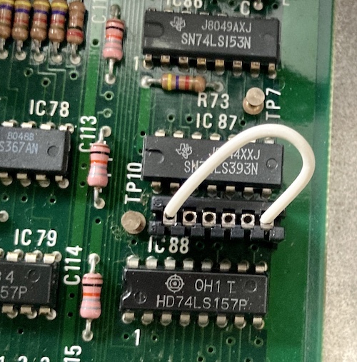
I decided to follow the original design, and put a temporary jumper wire in parallel across the pull-down resistor on my board to short the signal to ground.
By then, I had also cleared off the sewing table to restore it to its original purpose (fixing stuffed animals, sewing buttons back on clothes, creating artisanal jean-jacket cozies for my toy computers) and so precariously stacked the entire mess in front of the NEC MultiSync 3D that I fully recapped in a previous entry. This monitor looks great, although it does make a lot of slightly concerning fast-cycling “relay clicking” noises when I turn the PC-8001 off. It might be a good idea to revisit the power supply in this PC-8001 in the near future…
Now, the PC-8001 hesitated for awhile before starting normally, and the lights on the PC-80s31 disk drive illuminated dimly. This made me suspect me that I screwed up the floppy cable pinout, and looking at the numbers written on the connector told me all I needed to know.
I had assumed, being a floppy drive, that the pinout was odd-even like on a 34-pin 3.5” or 5.25” floppy drive cable.
In actual fact, the 57-series Centronics connector is 1-18 on the top, and 19-36 on the bottom!
This meant that my connector on the PCB was totally wrong, and I’d need to either make an elaborate ribbon cable, or re-spin the board to correct for it. I had a hunch that this was going wrong when I tried to buzz out the grounds on the 80s31 drive and found that it was sparser than I expected.
I attempted to compensate for the side effects of the re-spin, but I lost a lot of the nice routing from the original version. That’s okay, it’s all low-speed stuff. I put all this stuff aside while I waited for a re-spin.
As soon as I sent it away, I got a bad feeling that I was running a risk by pulling the trigger on this one too early, as I should have taken apart the 80S31 and confirmed the pinouts on my own (Enri’s excellent website of course explains which pins go where on the floppy drive’s 8255.) It also didn’t really make sense with the “34-pin” pinout now, anymore, which was another red flag.
You gotta live a little sometimes, right?
Version 2
For version 2, I took the downtime while I was waiting for the board to make another monochrome video cable. Now, the JB-1260M(A) could be paired with the PC-8001, and the original cable would magically turn up immediately in a pique of jealousy.
Making the cable was still annoying, because soldering DINs are always kind of annoying. I think the overall quality is much higher than the first time around, due to better tools and more practice having made cables.
If I were to make this cable a third time, I’d probably make it much longer. After trimming the cable, it’s just over 75cm, which is just barely long enough to reach the port on the back of the monitor when the computer is sitting at a comfortable distance from it. Not a super pleasant experience, and I have no real excuse for making it so short as it came from a box of bulk ethernet cable that I’ll probably never use up.
This is much sharper video than when I did the same thing with the PC-8801mkII way back when. I strongly doubt that my cable-making skills have improved… it’s all down to the fact that the monochrome monitor isn’t trying to interpret colour where there is none.
That was a nice way to spend half an hour. Now, I waited for a couple more days for the board to arrive.
Once the new board arrived, I quickly transferred parts. I regretted not using sockets for the little DIP ICs, and I didn’t bother moving the 86 solder joints of the combined pin headers over. Not having to do the cables twice definitely made this one come together faster than the first one.
This board also did not work, but there was slight improvement: the bodge for was no longer necessary. Still, I figured that it was time to go back to the drive itself, and at least figure out which pins were continuous with frame ground.
From what I could tell, I was way, way off, possibly due to my initial confusion about the order of the Centronics pinouts not being fully thought out past “physically pinned wrong.” Working from a multimeter, I could tell that pins 9, 10, 11, 12, 13, 14, 15, 16, 18, and 36 were continuous with frame ground and nothing else.
Indeed, after going back to the very page where I got the 80S31 pinout in the first place, I could confirm that’s what it said this whole time.
Armed with this info, I now saw the problem: I had laid down the wrong symbol in KiCad and then gleefully ignored the numbers as I went about transferring the table from the electrelic page.
I have no excuse for this, especially not letting it happen twice.
Especially compared to the v2 iteration, version three made such an easy route that it was almost like it was how the board was designed in the first place.
Do as I say, not as I do: actually check your pinouts against the real world, or you’ll end up making three of the same board on the same mistake every time.
Version 3
After an hour of putting it together, you may be surprised to hear that it still didn’t work. Neither drive tried to make any motion at all, even when its head was pushed into a track far away from track zero.
It was at this point that I became a little suspicious of the floppy drive, as I was sure that I had the pinout right, sure that I had the interface board right, and yet I was still being let down somewhere. Was this forty-year-old floppy drive in unknown condition, which I had done absolutely no maintenance to, potentially bad?
A quick check on YouTube showed a video where, like virtually every other NEC floppy drive I’ve ever seen, the PC-80S31 floppy drive’s motor started spinning as soon as a disk was inserted. Mine wasn’t doing that.
Mechanism checking
I thought it was strange that the 80S31 wasn’t spinning the motor on the drives. In addition, it didn’t re-seek the head at power-on, and it didn’t seem to be doing much of anything in general.
I also noticed that, even when I had my PC-8033 interface unplugged, the drive’s lights were still dimly lit. That didn’t feel right to me, especially since on most of the other NEC products I’ve worked on, the “motor on” signal is tied up with the LED.
Dismantling the 80S31 isn’t too bad. I took apart as much as I could without pulling the drives out. This gives you just enough room to loosen the data and power cables from the topmost disk drive, which was a good place to measure voltages from.
Voltages were fine, at least at rest. With the drive enclosure turned on, I got +12.4V and +5.0V on the +12V and +5V rails respectively, and -5.3V on the -5V rail, which is used for the 80S31’s motherboard’s dynamic RAM.
I decided that it would be a good idea to independently bench-test the drives, so I pulled drive one out of the front of the enclosure. Unsurprisingly, it turned out to be a TEAC FD-55B.
Like every other time I’ve used a NEC-pulled drive on a Greaseweazle, I screwed around for a half hour wondering why it wasn’t writing properly. Once again, it was that I didn’t set the head load strap (on this drive, the jumper HS.) I’ve made a note of it on the Greaseweazle itself. I swear I’ll remember next time.
With the Greaseweazle controlling it, the drive seemed to be able to seek and write-with-verify a d88 image with no problems. This meant that the drive probably wasn’t at fault. I cleaned the heads and gave it a little bit of lubrication anyway, then shoved it back into the enclosure.
My next stop was to verify the pinout on the PC-80S31. Using Enri’s schematic, I buzzed from the 8255 PPI on my new board to the 8255 PPI inside the PC-80S31 drive unit. Spot testing passed, as did a quick check to make sure I had wired up to the correct pins.
As far as I could tell, the drive was okay. Back to the adapter, which is still the most likely source of failure, because it has not worked yet.
Selection Pressure
I knew from reading the British PC-8031B manual that resetting the PC-8001 was supposed to make the drive seek to track zero.
I remembered that on the first ill-fated version of this board, I didn’t see a chip select being enabled. I did not actually check that this time yet.
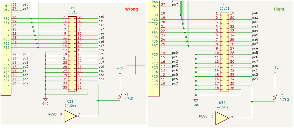
When I checked to see if the 8255 was being selected, I found that it most certainly was not. That line was consistently high! Selection of the 8255 requires a bunch of address lines to go high, which uses a 74LS30, as it did in the original PC-8033 interface. That’s an 8-way NAND gate.
I had it wired up like this:
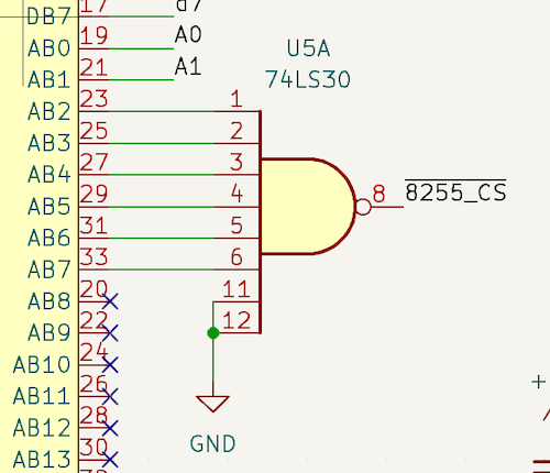
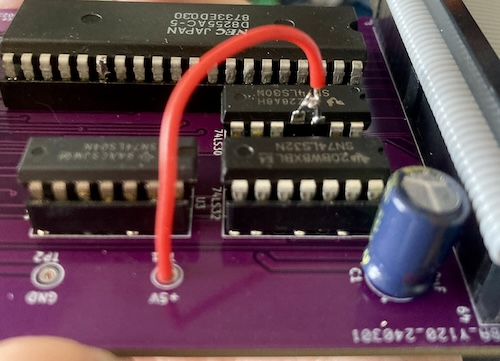
However, the data sheet for the 74LS30 says, uh, this:
Ground is pretty low, yeah. So that explains why it was never being selected, at least. I wish I had caught this earlier on one of the respins, but I was too busy chasing the cool NEC floppy unit hooked up properly. At least it’s an easy bodge…
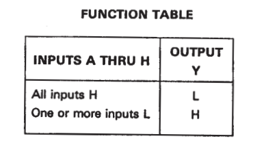
Woof. Don’t look too closely at those solder joints.
To bodge this, I pulled the 74LS30 out of the socket, bent legs 11 and 12 up, and wired them to the nearby five-volt test point.
Now, chip select oscillated during the runtime of the PC-8001, but the floppy drive still didn’t come alive. I scoped the chip select pin to the PC-8033’s 8255, and saw that the “high” voltage coming out of the 74LS30 was about 2.40V. That seemed a little low, especially since the datasheet for the 74LS30 said that VOH was a minimum of 2.4V and typically 3.4V.
At this point, I decided to do something very basic: check the voltages. The +5V and GND test points revealed that the 8033 clone board was only getting about 2.8 volts. That’s not really enough to do anything!
I pulled the extension cable and made sure the female end was mashed tight together. After re-seating it, I now had 4.80 volts, and the PC-8001 seemed to freeze when trying to access the PC-8033/PC-80S31. Pushing reset made it freak out and fill the screen with garbage, almost like it was loading crap code on the wire from a bad connection. The 80S31 still didn’t activate any of its many motors.
I suspected the expansion edge on the PC-8001 was not making great contact due to years of accumulated sludge and corrosion on the fingers, so I took a pencil eraser to it. The pencil eraser came away black from even a light rubbing with the case still closed up, so I decided to dismantle the PC-8001 and remove its motherboard for a deep cleaning of the edge connector. I began to understand why, for the PC-8001mkII, NEC went towards a more traditional female edge connector and male card expansion design.
The biggest challenge here was taking the motherboard out of the case. I had to take the board out because the bottom side of the edge connector is not really accessible when the case is together. There’s only about a 0.75cm gap, which is not enough to stick an eraser through, and I couldn’t see what I was doing even if it had fit.
That motherboard is held into the case with triangle-shaped plastic clips, which have aged and didn’t want to compress far enough to let the board out. I started to worry about damaging the board, so I decided to measure and then clip off the clips with my side cutters in order to remove the board. This was probably a mistake, but at the time it felt good. Screw you, old clips!
Scrubbing each finger with a pencil eraser made it obvious just how oxidized the expansion edge really was. I saw lots of dirty shavings coming off the eraser, and I could actually watch the metal brighten up with just a few passes. I would not have guessed these were as bad as they were, especially considering I gave it a thorough scrub with some alcohol when I first got it. This is a good lesson for the future.
I finished this manual labour off with a couple doses of Deoxit to help clean, lubricate, and, if you believe the marketing, add a layer of mystery goop to protect the expansion edge fingers.
Once that was done, and once I built a set of sketchy new mounts for the board out of T-nuts, some nylon spacers, and M3 screws, I was able to fire up the PC-8001 and give it another brave try. The disk drive still refused to move, but checking on the scope showed that the line was now a strong, confident +5V with excellent rise time.
I did notice at this point that the drive 0’s access light flickered to full brightness a little bit when I hit the reset button on the PC-8001, so the reset signal was making it to the 80S31’s motherboard and something was going on from there.
I also went back and re-read Enri’s excellent PC-80S31 writeup. It included the helpful info that the dimly-lit access lights were normal – the lights light up 100% when accessed but don’t return to full darkness.
access lamp
Lights up at 20% brightness when in standby mode Lights up at 100% brightness when the drive is being accessed.
Going from some 2003-era message board rumblings, I swapped the 8255 inside the disk unit for a newer one from my hoard, and deoxited the socket, but it made no difference at all. Replacing parts with no evidence whatsoever that the parts are bad tends to do that, but I had a stack of 8255s and apparently too much free time.
Drive The Drive Yourself
I knew now from reading Enri’s documentation and the various message-board rumblings that, on startup, $91 had to be written to the “control word” of the 8255 on the PC-8033 side, which is to say the port the PC-8001 knows as $FF . This sets the port in/out directions on the 8255 and prepares the adapter to send commands to the 8255 inside the disk drive. I assumed that it would then send the “initialize” command, $000 .
After reading a bit more on the 80S31, I had some good candidates for signals to probe. The ATN signal originates from PC7 on the PC-8033’s 8255, and is a one-way signal that tells the 80S31 if the next instruction is a command (H) or data (L.) I decided to probe that signal and see if it was cycling. It seemed to be consistently high after reset, which seemed a little strange to me, as I would have expected some data to be sent.
I wrote some quick BASIC code to set the PC-8033 interface’s 8255 ports using the OUT keyword, and in output mode I was able to control every single bit of all three ports, making them pop high and low on the scope as I commanded. That, to me, showed that the decoded connection on my clone board from the PC-8001 to the 8255 was working, and the 8255 was working too.
Buoyed by my success, I wrote a more complicated program to issue the “drive status” command ($007 ) to the drive. This was a fairly involved program, mostly because of all the bit arithmetic and manual toggling of the handshaking ports that was required.
Nothing happened; the flag for “command acknowledged” was never raised by the disk drive.
I realized that I had another computer I could use to test with: the PC-6001mkII also contains a similar “intelligent floppy interface,” and all I’d have to do is make a 36-pin Centronics-to-Centronics cable for it. After doing so, I plugged in the PC-6001mkII to see if that would be able to boot the floppy drive, but the same behaviour persisted.
That said, I was not confident if I needed to enter a specific mode of Extended BASIC or hold a key at startup to boot off floppy7, and the keyboard on this mkII was (as typical) not working properly. Not a great test, but it was making me more confident that it was not necessarily my adapter board’s fault.
Blame Someone Else
With a sinking feeling, I realized that the last component left to blame had to be 80s31’s motherboard. It was the only part I didn’t have at least one kind of double of on hand.
I decided to work backwards from the floppy drive and verify the function of the ICs on the 80S31’s motherboard. Unable to find another, I pulled a µPD765 floppy disk controller IC out of the same parts motherboard - a battery-rotted Hitachi B16EX-II. This was my first time using hot air on the topside to melt any difficult/plugged through holes, and it worked really well. The last stuck pin came out of the board with only a little bit of swearing and jiggling.
After swapping in the “new” 1987 FDC IC, I noticed absolutely no difference. Parts swapping is not really scientific diagnosis, but imagine how much fun it would have been if it had worked. I also accidentally took the opportunity to find out if the drive unit magically started working with the second drive disconnected (nope.)
With the board already out, I decided to dump the TMS2516 UV EPROM that contained the drive unit’s firmware. I doubted that it was corrupt, but it was socketed, and it can’t hurt to have a backup on hand of an ancient UV-erasable ROM.
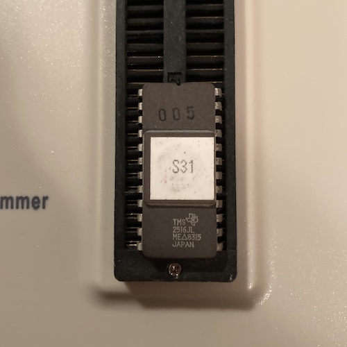
To dump this ROM, I had to turn to a new friend: my GQ-4x4 ROM programmer. I would usually use the trusty ol’ TL866 for this kind of thing, but the TL866 software doesn’t support it, not even for reading. This is probably because the device needs 25 volts to program.
I did two dumps, because I have grown accustomed to doing this sort of thing. And it’s a good thing I did, because those dumps were different:
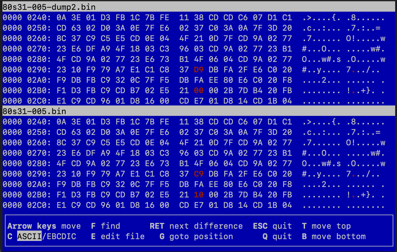
I had heard that the quasi88 disk.rom was the same as the 80S31 BIOS ROM, so I decided to fish out my copy and diff them:
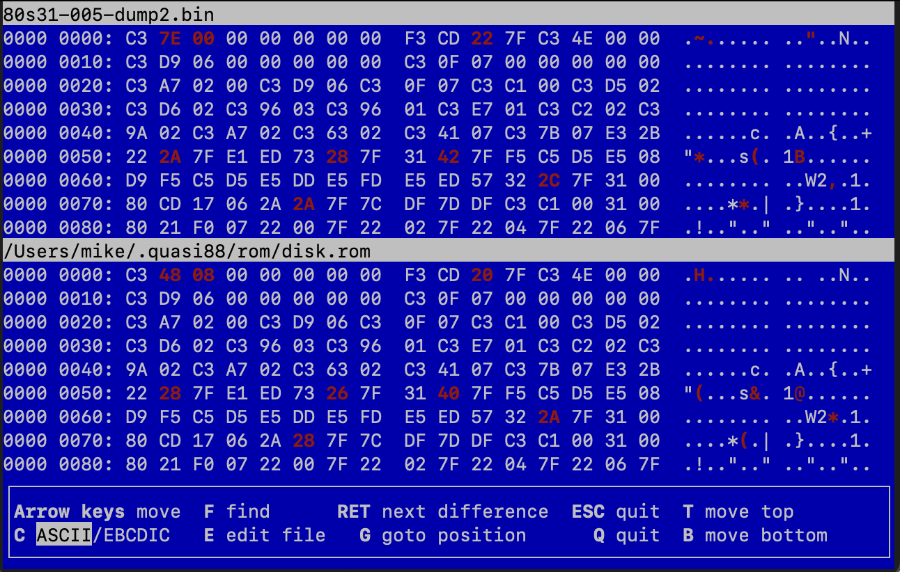
That does not look like the same ROM at all. Or at least, it looks like a similar ROM, but with wildly different addresses in it. Things don’t get any better further into the ROM, which makes me agree that the PC-8801mkII disk ROM is a descendant of the 80S31 ROM but is not necessarily the same one.
For a tiebreaker, I had blog superfriend CDP dump his working PC-80S31 multiple times and diff the ROMs. His dumps are all the same, but they’re not the same as either of mine:
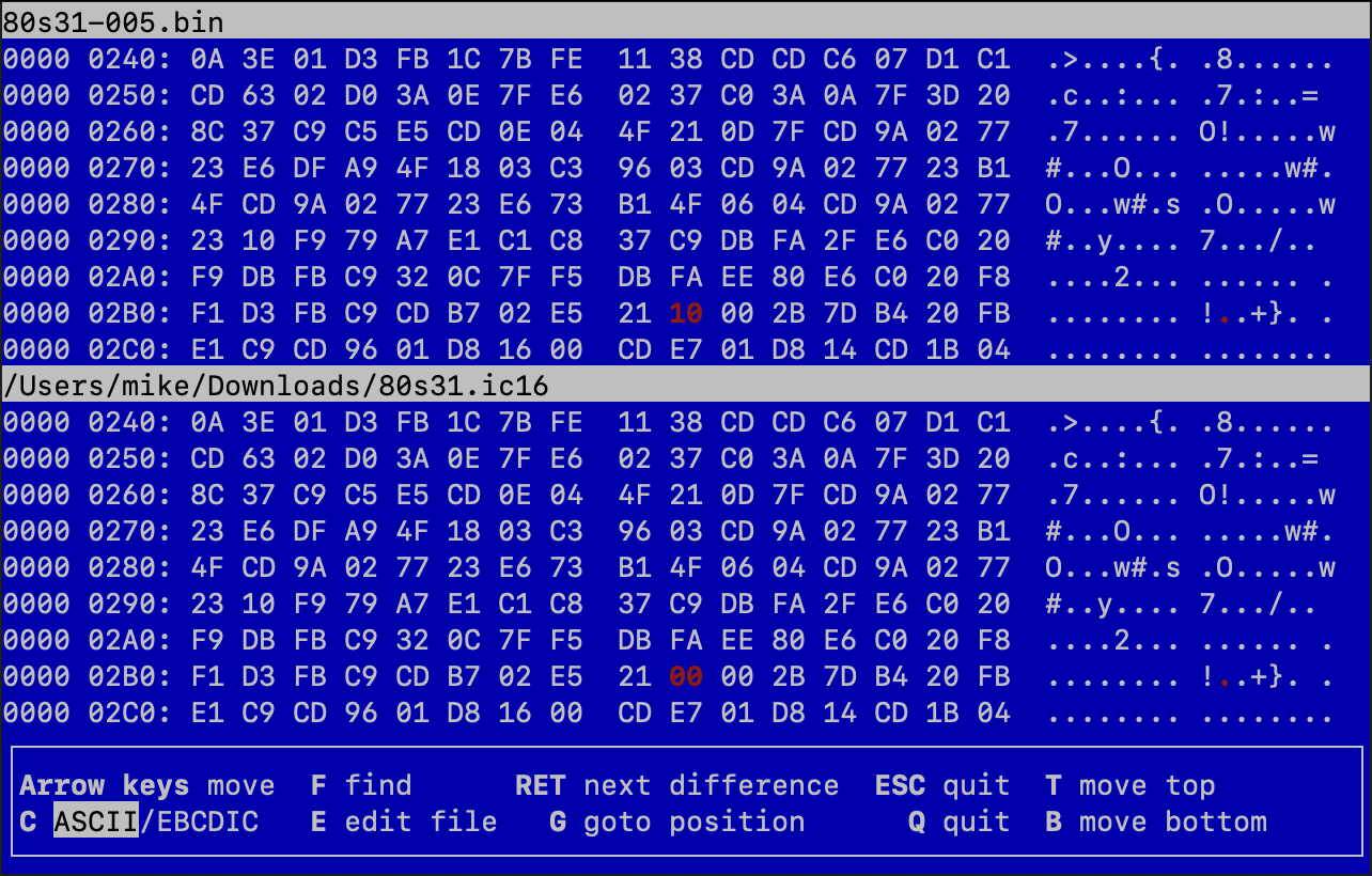
Just one or two bytes being flaky doesn’t really explain a big fault, but it’s possible that more dumps would have fingered more intermittently-correct bytes. And when it’s running inside the drive, that ROM needs to be pretty consistent. I’m not sure I trust that TMS2516 enough to rewrite its existing ROM; let’s write a new ROM.
I asked around to see if anyone I knew had 2716s on hand, and blog friend Chartreuse politely reminded me that he had already given me an Atmel 28c16. Of course, that 28c16 was meant to build his 6809 kit computer, the Fennec, but I hadn’t, uh, gotten around to it yet. So I used that one, only to find out that it refused to program and verify accurately, except as a CAT28C16A, which worked fine. Such is life in the 2K EEPROM world.
Now, with the not-really-an-Atmel, but most likely way less flaky 28C16 stabbed into the board, I was ready to test again. Unfortunately, there was no observed difference with the working ROM attached, either. This was starting to get frustrating.
Even though the voltages looked fine on a multimeter, I wanted to check the tantalum bypass capacitors on the board to make sure they hadn’t magically failed in the weeks since the last check. I’ve had them short before, but they turned out to all be fine, testing out for about 0.75Ω of ESR out of circuit.
The Lifechanging Magic of Buying Two of Them
I didn’t want to derail this project any further by tearing down the 80S31 and writing diagnostic software for it. For the time being, I decided I would grab another drive. Unfortunately, the PC-80s31s that were on offer the second time around were now more expensive. Almost as if someone had bought the cheap ones already. Even though it meant I’d have to make a new cable, I grabbed a PC-8031-2W.
As you might expect, the older disk drive is absolutely immense. It’s mostly air inside, though, as the control board seems to be just stuck above two very tall belt-driven floppy drives. Did I inspect these before trying to hook anything up? Absolutely not.
It has an edge connector on the back telling me to connect it to a floppy controller, so I quickly made up a 34-pin straight-through ribbon cable for it.
I thought I would be able to simply slip it onto the leftmost pins and not interfere, but the IDC head is wide enough to rub on the “extra” pins of my PC-8033 clone board. I briefly considered clipping those pins off – I had a feeling I’d end up revising my 8033 board at least one more time – but resisted the temptation.
I grabbed a right-angle female 34-pin header to see if that would help, but that header also has a chunk of reinforcement around the edges that kept it from mating. This is probably a deliberate feature of the connector, so that my dumb ass can’t end up one pin off. Bravely, I decided to simply… bend the pins out of the way. Nothing permanent, you see.
When I fired up the 8031, it made no noise at all, but lit its power light. That’s a lot better than instantly bursting into flames. After checking connections, I went to fire up the PC-8001, and heard the very loud sound of dry motor bearings. The 8001 was driving the floppy drive’s motor pins! My adapter works!
Well… sort of. The 8001 would load for awhile, the drive would make a few little seeking sounds, blink the access light, and then make one final solenoid clunk. Then I’d get kicked out to regular old non-disk BASIC. But this was progress.
Don’t Turn It On…
I started to wonder. Is it possible that this forty-plus-year-old floppy drive that had clearly been stored in poor conditions, then shipped across the entire world, that I fired up without inspecting it in any way whatsoever, might be dirty?
I ejected the disk to find a few chunks of dirty lint on it. Japanese lint! Another clue. But what could it mean?
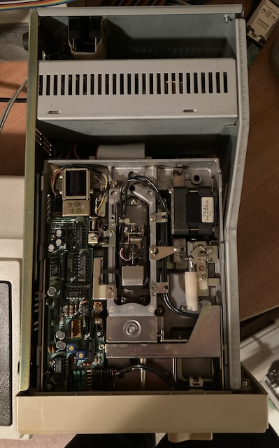
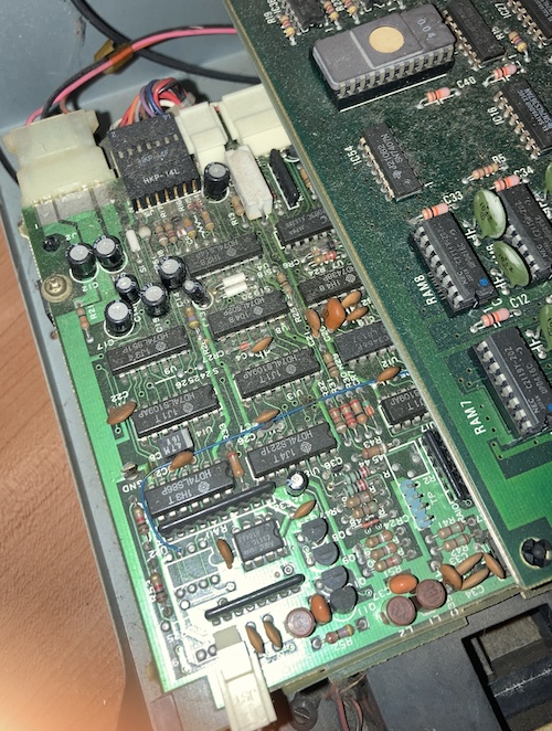
Removing four immaculately-rolled fine-thread screws (this thing must have been expensive8!) I was confronted with the main logic board of the floppy unit. And also like three pounds of cobwebs, mostly around the extremely heavy full-height floppy drives.
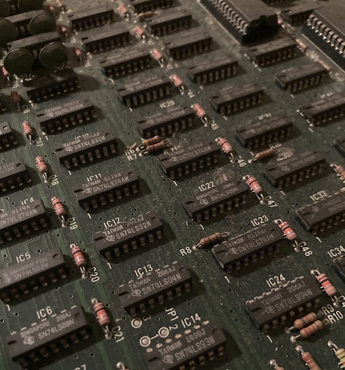
Look at all that beautiful discrete logic. No PLDs here. The µPD416C DRAM is all socketed too, unlike the 80S31, speaking to NEC’s relative lack of confidence in the quality of their yields at this point in time.
Although I couldn’t get a good shot of it without removing the top board, I couldn’t resist grabbing a snap of this weird 14-pin connector on the floppy drives. This harness probably connects the logic board of the floppy drive (also still containing a fair-sized glob of discrete 74 logic!) to the motor control hardware.
The data cables are the regular old 34-pin ribbon cables, each connected separately to a male edge connector on the logic board. I was tempted to just hook up a Gotek at this point, but I didn’t want to reach blindly inside this thing and risk tearing a cable or getting my hands all gucky. So off to visit Mr. Blower and Ms. Driveway they went!
After blowing out a bunch of swarf, but less than I expected, I found that some screws were stripped and others were entirely missing. Great! Someone’s messed with this in the past, that’s what I always like to see.
Removing the drives isn’t too bad, but it’s a little precarious as you’re holding a heavy metal object into a flimsy metal object as you’re unscrewing it. I flipped the whole assembly upside down and put it on a moving blanket to protect the drives when they fell. ESD-safe? No, but a lot safer than the driveway.
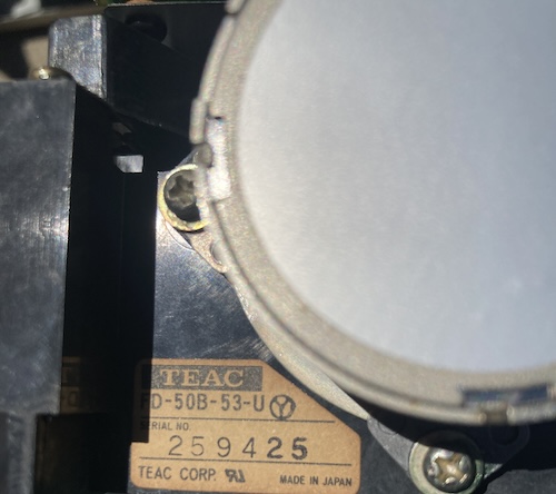
Now that the drives are out, we can see behind the giant head-stepper motor to realize that they are TEAC FD-50B-53-U drives. This filled me with relief: I’m glad they are not some shonky homemade NEC thing, but instead a sturdy, rebuildable TEAC product.
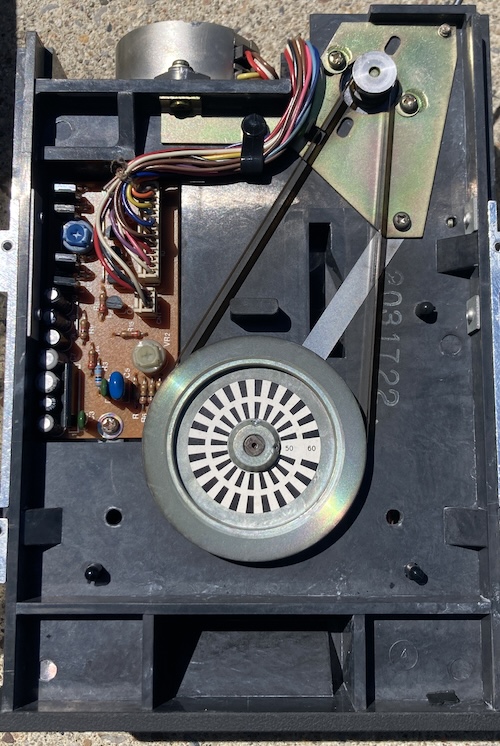
Flipping them over, I realize that both drives have completely intact belts. Not only that, but they have reasonable tension as well. This is nothing short of a miracle. I like the strobe-timing marks on the spindle motor, although I’m not sure where the ignition distributor is on this disk drive in order to plug in my timing light.
The “50” and “60” marks made me start to wonder if this drive is timed differently for 50Hz and 60Hz parts of Japan. That would be super weird, as the drive is powered off of DC9…
I marked the drives and set them aside to be tested on their own. Then I set about plugging in the FD-55Bs from the PC-80S31, which I knew were fine, because I had used them with the Greaseweazle to write and verify the Disk BASIC disk.
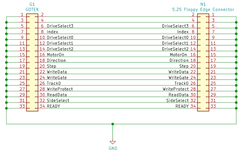
I considered also plugging in a Gotek too, but I didn’t want to make up yet another cable.
When I ran this, I heard the motor start, I heard the head seek (!!!) and then it didn’t load Disk BASIC. Peering into the case and pushing reset, I saw that the head would seek forward to about the middle of the disk (the directory track) and then go back to track zero. That looked like something was very much alive in there, and that a computer was driving things.
I grabbed my second disk, a copy of S-DOS, and popped that in instead. I didn’t know if I wrote the Disk BASIC disk properly, and there’s a good chance I didn’t.
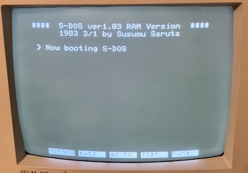
I swore a little bit in surprise when this popped up.
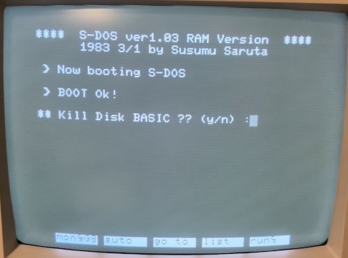
S-DOS loaded after a few seconds, and asked me if I wanted to kill Disk BASIC. I’m not sure why you would want to do this (more free RAM available?) nor do I really know the true purpose of S-DOS, as it came out of the TOSEC PC-8001 archive with no documentation.
Seeing as I am against violence in general, I decided to let Disk BASIC live. My reward was that S-DOS punted me out to something that seemed a whole lot like Disk BASIC, and let me mount the disk for reading.
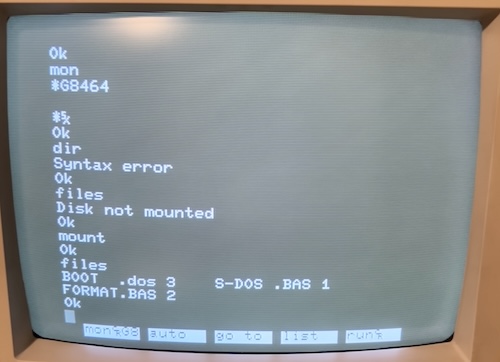
The PC-8001 requires you to use mount to mount disks and remove before changing them. I assume that this is some kind of cache strategy, though the reading I’ve done so far (being mostly “why doesn’t my homemade PC-8033 work??”) is a little shallow.
Conclusion
I’ve pushed my luck (and wallet (and free time (and sanity))) enough for one entry. I think I’ll leave it at that. Let’s review what just happened here, before you go.
I picked up a perfectly-working (but rusty) NEC PC-8001, and figured out how to get colour video to work.
That wasn’t enough for me, so I bought a PC-80S31 5.25” disk drive, and cleaned and tested its drives using a Greaseweazle.
Then, I designed a PC-8033 clone adapter from photographs and pinouts to be able to drive that drive from the PC-8001. I made a ton of mistakes and slowly worked my way through them with more board revisions and bodge wires. After I figured out that the adapter was probably correct, I suspected that the PC-80S31 itself had a fault somewhere on its motherboard.
I built a cable to test the PC-80S31 with my PC-6001 and PC-6001mkIIs, and then finding out that it didn’t work there either, became even more confident that it wasn’t my adapter.
After some further diagnosis, including discovering that the PC-80S31’s BIOS ROM was flaky, I determined it would be faster to buy another disk drive.
I bought an untested PC-8031-2W from Japan, and had it sent here by slow boat. I then built a third cable to use the 34-pin interface on this drive. This proved to not work either, and after some investigative work I determined that the full-height 5.25” drives in it needed to be cleaned up and maintained.
Rather than maintain the drives, I pulled a known-working drive from the PC-80S31, and stuck it into the PC-8031-2W. At this point, it seemed to work, and I was able to boot S-DOS (but not my copy of Disk BASIC.) Hooray!
There is still lots left to do on this machine:
- Fix all the clips that I broke on the case removing the PC-8001’s motherboard for cleaning;
- Figure out what is actually wrong with the PC-80S31’s motherboard;
- Figure out what is actually wrong with the PC-8031-2W’s disk drives;
- Figure out if my adapter actually does work with the PC-80S31;
- Figure out why my copy of Disk BASIC didn’t work, and write one that does;
- Find a videogame or something that I can enjoy on this machine.
Phew! But at least we can rest easy, knowing that a new open-source piece of hardware now exists for the PC-8001, so you don’t have to spend nearly three hundred dollars on a piece of vintage NEC hardware that consists almost entirely of a single 8255. And that’s what this dumb blog is all about. Thank you for joining me.
Here is the link to download the Gerbers and KiCad source files for the NEC PC-8033 clone adapter, which is released under the GPL.
-
This information is from this excellent Kuninet article, where the writer has a truly impressively kitted-out PC-8001. ↩
-
This seemingly silly price shouldn’t be a huge surprise, as the PC-8033 cost ¥17,000 when new, which is more than the ¥13,500 NEC Character Display monitor. NEC later rolled the 8255 and supporting circuitry onto the PC-8001mkII, and exposed an “FDD port.” An orphaned adapter that was only ever used on one model of computer is going to usually be a little expensive in the aftermarket, but it’s the kind of thing I love to make. ↩
-
As you might expect, because the protocol and timing are so abstracted on the 80S31 design, it is easy to make a modern replacement for it. There are several hobbyist projects to do so, most notably the Raspberry Pi PC-80S31 emulator. The build instructions do ask for an “FDD port,” however, so I believe that it still needs a PC-8033 for use with the original PC-8001 model. It probably would not be too hard to modify it to also emulate the 8255, but I haven’t looked at the code at all. ↩
-
The PC-60S31 seems to have a different mainboard entirely, using a µPD8049 (MCS-48) microcontroller instead of a Z80. This shows that NEC at least understood the value of abstracting the protocol away.. ↩
-
Although I haven’t confirmed this myself, there are many references in the Japanese hobbyist material to a shogi game that uses the disk drive’s Z80 as a coprocessor to speed up the computer player’s search tree. The drive’s own memory is also used as a cache buffer by several aftermarket DOSes such as S-DOS. ↩
-
Mostly, I was paranoid that I would rotate or mirror the connector while assembling the board and accidentally end up shorting some logic output on the expansion connector to ground, damaging the PC-8001. The resistor would at least give that logic output a chance, by minimizing the amount of current that would be involved in the fight. That’ll teach me! ↩
-
According to the P6 technical information reference, the original model PC-6001 will not auto-boot floppies, even with an Extended BASIC cartridge installed. ↩
-
According to this price list, the PC-8031-2W originally launched at ¥288,000. This is a good discount off of the original PC-8031 at an eyewatering ¥310,000. That’s nearly as much as the PC-8001 cost. If they had waited to get a PC-80S31, they would have only paid ¥168,000 and saved a bunch of desk room in the process! What a deal. ↩
-
The timing light, of course, would be powered off of AC and strobe at a different rate on 50hz. ↩