You Might Have To Tomy Twice
Tags: computer tomy tomy-pyuuta pickups repair
I always wanted to try out a Tomy Tutor, and so I assumed that the Pyuuta was an identical computer. After all, it looks the same! This was one of those machines that I bought without knowing the details. All I knew is that Mandarake wanted an absolute fortune for any boxed Pyuuta games they had on the shelf, and that a good number of the retro-y Japanese Twitter folks seemed to have fond memories of the purple wedge. Let’s find out why.
Like a lot of my upcoming Japanese-market projects, this TP-1000 is not actually a new purchase. It was actually purchased in January 2021, which means it had been sitting in the Buyee warehouse for over a year. Why? Cheap seamail shipping to Canada from Japan was suspended due to the lack of shipping capacity, so they’ve been graciously storing it for free this whole time, along with a lot of other stuff I’ve won (the shipping snafu reduced the number of competing bidders for a little while.) I ended up paying through the nose to ship this DHL in March 2022, which was probably a mistake.
While I was waiting for the computer to wend its way from Japan, I managed to track down and devour the excellent floodgap.com page on the original Pyuuta. It’s got all the details and history anyone could want on this little 16-bit computer, and so I’ll be linking to it heavily throughout this post.
16-bit computer?
Yes, 16-bit. It pairs a TI TMS9995 (not even used in the TI99 outside of an extremely fancy third-party expansion card!) with the TMS9918 VDP I’ve already become intimately familiar with from my ColecoVision-compatible clone called Leako. It even has an SN76489 sound chip!
Unfortunately, the BIOS and system design don’t allow the end user to take advantage of a lot of the unique features of this chipset. Not all VDP graphic modes are available, the promised 64K and TI99-converter expansions never happened, and although the CPU has complex 68K-esque features like remappable interrupt/trap tables, hardware-accelerated paging, and DMA, they’re not exposed to the user at all. And just like the TI99, all of the system RAM is stuck behind the VDP, forcing the CPU to use I/O port calls to make anything happen outside of its internal 256-byte scratchpad RAM. Pretty much all the gory hardware details are also available on the floodgap site; Cameron Kaiser has done a tremendous job keeping the shrines maintained for this machine.
If you’ve watched a lot of Disney movies from the early-80s, you might recognize the Pyuuta from this scene in Where The Toys Come From:
Pretty sure that’s authentic TMS9918 computer graphics, too. Doing stop-motion animation with a CRT must have been hard!
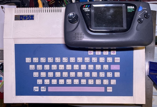
As you can see, the Pyuuta isn’t an extremely large machine. Its size is actually pretty close to perfect (in my mind) for an 80s wedge, with a generous overhang on either side of the keyboard and a nice amount of wrist rest. You’ll soon see that Tomy clearly got a bulk discount on plastic, however, as this case is virtually empty inside.
You’ve got your basic BASIC
Unlike all of my other Japanese computers, this keyboard is Japanese first.
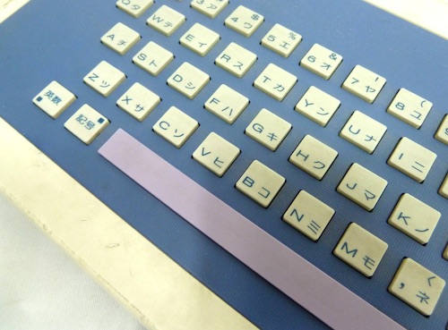
If you don’t hold down the “English SHIFT” key in the lower left, it will type kana by default. This extends to the built-in BASIC – which is also in Japanese, a surprise but not an unpleasant one. Your own appetite for quirk may differ from mine.
The built-in BASIC on this machine is called “G-BASIC” for Graphic BASIC. You could add a weird-looking “BASIC-1” adapter into the I/O expansion slot to add an additional, expanded BASIC. This better BASIC is simply called “BASIC,” and was built into in later models of the US Tomy Tutor and the Pyuuta MkII from the factory. It’s also in English, and said adapter came with an insertable keyboard overlay with the English keywords, Casio PV-7 style. Unfortunately, I don’t have a Pyuuta MkII or a BASIC-1 adapter, so I am stuck with just the very, very limited set of Japanese GBASIC keywords.
Even without the language barrier, though, GBASIC would be missing a lot of features from other 80s computers’ BASIC, shaved off in either the name of reliability, simplicity, or just to speed development. Take POKE, for instance, a BASIC command which writes a user-specified byte to a memory location. Pretty much every other machine of this era lets you directly mess with memory, making it possible to use cool memory-mapped hardware features from BASIC or inject arbitrary code into innocent parts of the computer that don’t know any better. Not so on the Pyuuta GBASIC. Without equivalents to POKE and PEEK, or a machine language monitor, the Pyuuta’s G-BASIC (and regular BASIC, too) can feel very limited indeed.
However, I enjoy the idea of tweaking a forgotten machine like this. Without a vibrant hacker scene, it’s likely that there are all kinds of cool peripherals and facts still waiting to be discovered, and there’s nowhere else in town I can go to try my hand at writing TMS9995 assembly, is there?
Does it work?
Even though the computer came with the grossest AV cables I’ve ever seen, whatever this green slime is (copper corrosion?) didn’t seem to have spread to the actual body of the machine.
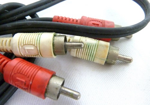
These RCA cables are not the originals (note the “L” and “R” markings when the Pyuuta’s white output is composite video) so they went in the trash. Thank you for your service, gross cables. Your journey has ended here, thousands of miles from home.
As for the body of the computer, this poor thing has been pretty thoroughly beaten up over the years. It has dents in the plastic, cable burn on the bottom, and is just generally very dirty. I decided I would take a look around to make sure nothing had been knocked loose, burned, or had foreign bodies stuck in it, but then I just plugged it in and started it up anyway.
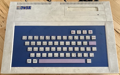
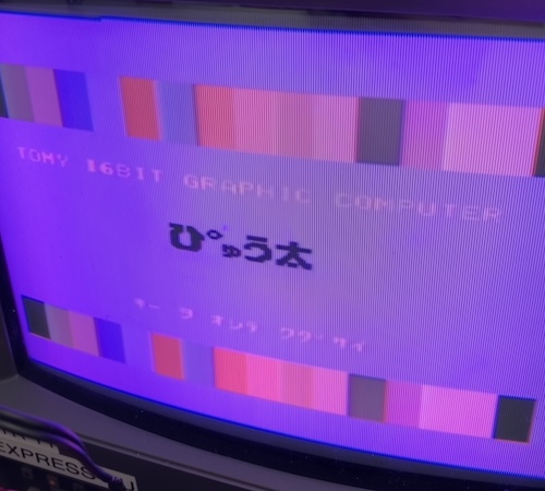
I plugged it in, turned on the power, and I was greeted with the Pyuuta boot screen. Boy, it looks familiar. After this, I tried out G-BASIC, but was unable to remember enough written Japanese to get it to do anything, and so switched off the computer. A successful first run.
It’s annoying that this is yet another machine with a hard-wired Japanese power cord. For now, it will run on my step-down transformer, but there is a lot of potential (and room) here to just power it with USB-C.
Another reason I might want to power it with USB-C is the state of the main power switch. It switches 100V directly, and if you switch it just a hair too slowly, it will make a worrying arcing noise1 and stink up the room a little bit. Clearly, the power switch is past its use-by date. Maybe that happened from being cycled too many times, as the Pyuuta appears to lack a reset switch and so this would seem to be the only way to restart the computer.
Let’s take a look inside to make sure nothing is super dangerous.
Getting inside is very easy - six fine-thread JIS screws. Tomy spent a buck on this thing and used threaded brass inserts rather than just driving the screws directly into plastic. Very reminiscent of the NEC PC-6001, including the creaky plastic that has shrunken since it was first made.
I couldn’t figure out a way to get the keyboard ribbon to come out, and I pulled fairly hard to do so, as well. Eventually, I decided I would just leave it alone and try to access the power switch from the gap between the upper and lower shell of the machine, which bore some fruit.
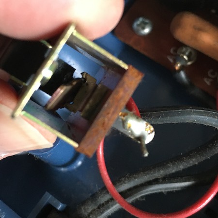
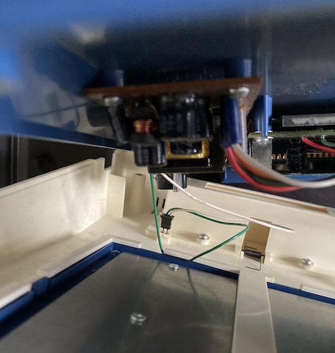
I found that the power switch, as expected, was pretty broken. The little clip that retains the see-sawing contact leaf inside the spring was cracked off from metal fatigue, and so the leaf could go wherever it wanted. While I was turning the around in my hands to inspect it, it fell into this awful diagonal position. No wonder it’s been arcing and making a stink of things.
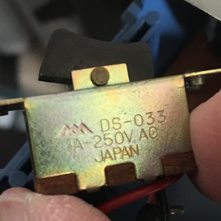
Although the power switch is clearly marked as a Miyama DS-033, I had no luck finding a direct replacement, although I did find this site which has the old datasheets and dimensions.
It would seem that the part is out of stock, although Miyama still exists (most likely because they didn’t spend money on keeping inventory around from 1983.) Their mains-rated switches all have plastic bodies now, which is a thing that makes a lot of sense. Unfortunately, they are all clip-ins, without the 36mm-wide “ears” that the Pyuuta case uses to retain the 22.5mm-wide switch body.
I cleaned the switch out as best I could with alcohol and deoxit, making sure that the contacts were clean, and then reassembled the machine. When I started it up, it still smelled like hot contacts arcing, and the “RT” (return) key now no longer worked after my attempt to remove the ribbon. This is going great.
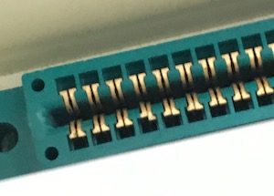
To make myself feel better, I used some tweezers to pop this bent pin on the cartridge slot back into place.
Decapitation
I went back into the machine in order to desolder the power switch so that I could fix it properly on the bench. Like the volume potentiometer on the PC-6001, that power switch is just crimped together, so it felt repairable. Whether it’s a good idea to rebuild a nearly forty-year-old mains power switch that has already failed once is a debate for the ages.
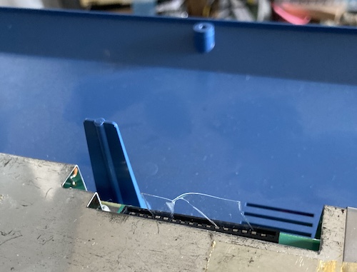
This time, I realized that part of the reason the top case was stuck on was that this wire for the power LED was trapped between the keyboard assembly and the case. I assume this must have been an assembly mistake at the factory, but the wire being trapped here prevented the keyboard from being popped out of the case, and it kept me from removing the top case at all. I ended up cutting this wire and splicing it back together around the section that was trapped in the plastic.
Now that I had some more access, I was able to get a better grip on the keyboard membrane ribbon. Unfortunately, the ribbon’s plastic core shattered in my hands, leaving broken chunks stuck in the motherboard-side connector, along with it some of the traces.
Great job, me.
I now had no working keys on this keyboard, but at least the top case was finally freed, and I could peer inside to learn the Mysteries of the Pyuuta.
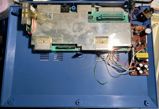
Holy crap, look at how much room there is in this thing. I could put a whole other computer in here. For the Tutor/Pyuuta 2, you’ll notice that there’s a little bit more stuff on the Tutor’s board, but not much more.
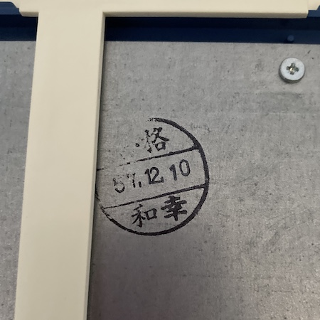
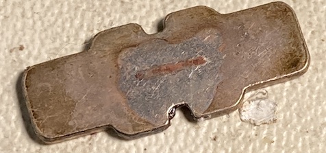
On the backside of the keyboard is this assembly stamp. If you’re used to Western dates, you might be surprised that they made this computer way back in 1957. This keyboard is actually from late Shōwa 57, or 1982.
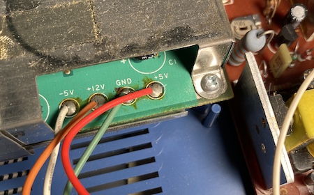
I took a quick peek at the power supply wires before I got started. This thing uses what I would generously call “unconventional” colours for its cable scheme. Luckily, they’re labelled!
Power Switch Fix
The power switch on this computer has been toggled a lot of times. I’m not sure what the history of this Pyuuta is, but someone certainly got their money’s worth out of it. As I shared back when I replaced the power switch on the Bad ADB Mac LC, it took a lot of toggles to wear out a power switch as a kid. A traumatic situation like that is probably what ended up sticking this computer first in storage, and then on the second-hand market that let me take it home.
While the switch does work, the arcing sound, the bad smells, and the intermittent power drops while the computer is running are all clues that this is a dangerous situation. 80s computers don’t really like being browned-out, for one thing, and I’d also prefer this one not to catch fire or produce a lot of stinky smoke.
Although I don’t know for sure, I suspect that this kind of metal-framed construction is no longer kosher for a high-voltage power switch. All of the newer replacement switches on Digi-Key appear to have a plastic exterior, likely to help protect curious fingers and avoid leakage to the frame. Unfortunately, none of them fit the case, so I decided to try my hand at rebuilding the old switch.
After desoldering the switch, I took a quick look at it. The terminals hadn’t come loose from their backing board, which is what I had originally thought happened. It seemed like something else was going wrong inside the housing.
I decided I had nothing to lose by taking apart the power switch. I used pliers to bend the crimps out until the switch fell apart, and kept the entire thing inside a ziploc bag in case a spring flew out and tried to lodge itself into my carpet.
Inside, the switch was covered in black sticky gunk. The switching leaf seemed to come loose with a stray thought, too. Something smelled really bad. Although I’m no expert, I believe that these are all things that a power switch shouldn’t do. A little cleaning-up will at least tell us what we’re working with.
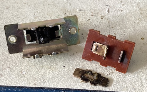
I used a pair of needle-nose pliers and a flathead screwdriver to open up the tabs on the back of the switch so I could work the fibreglass board inside out. It’s nothing very complex in here: just two terminals, with one of them also working as the pivot for the switch’s see-saw action.
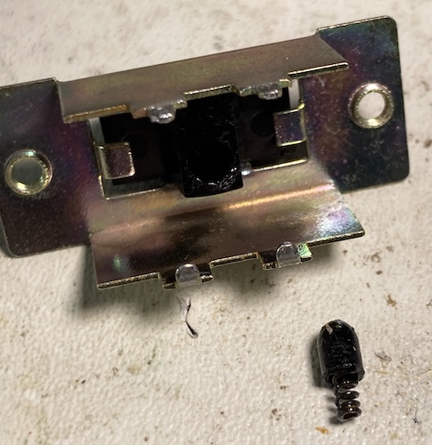
This is where I think the problem was. For lack of a better term, I’m going to call this the “follower.” It is a rubber nub with a spring inside. When the plastic toggle switch on the outside is moved by the person, this spring provides the force that pushes the leaf down on either side to make the connection.
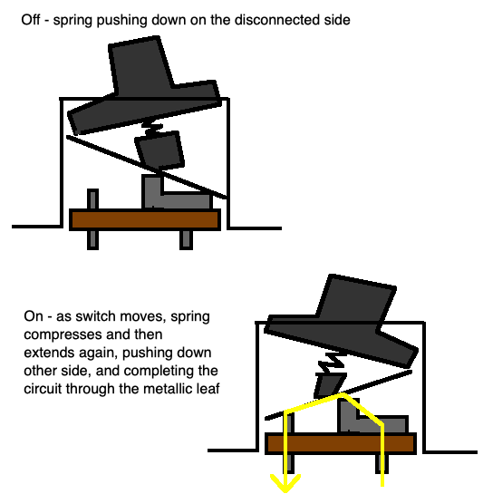
However, if you look very closely at the photo up above, it looked like the spring had some rust in it. If the spring was rusted together, then it wouldn’t fully extend. As a result, the leaf would be just ever so slightly hovering above the terminal.
Arcing and intermittent contact would result, and there was some evidence of charring on both the leaf and the “output” contact. The lack of spring tension also explained why the leaf was crooked when I first opened up the machine.
I cleaned up all the contacts with a grey Garryflex block. Now, they were shiny metal again. Granted, they are now more likely to corrode, but as my climate is a lot less humid than Japan’s, I don’t think it is too much of a risk. Just to be on the safe side, I applied a thin layer of auto-parts-store dielectric grease using an old McDonalds napkin.
As for the rusty follower spring, I chucked it into a little bit of Evaporust and decided to give it a day or two, to see if it would loosen up. And it did, depositing a bunch of nasty-looking orange residue into the bottom of the Evaporust. When removed, I was now able to compress it with my fingers, and it would “spring” back when I let go. Hey, maybe that’s why they call it that. I washed the spring off with alcohol, let it dry for a bit, and then reassembled the switch around it. I used a pair of pliers and some grimacing to pinch the crimps back shut against the board.
Now the switch’s throw action was confident, the multimeter showed 0Ω between the terminals when the switch was closed, there was no arcing as the toggle travelled through its path, and most importantly no bad smell or ominous fear. I would call this fixed, but ultimately I would still like to replace it with a new part, especially if it were going to another person or a particularly litigious museum.
Tiny Maintenance
Despite the fact that the screw posts have PC-6001-style metal inserts in them, the plastic of the screw posts had shrunken over the years and cracked around them. While none of the inserts were loose, I put a few globs of gel super glue around the cracks in the hope that I could shore them up a little bit.
I applied Boeshield T-9, a vicious little lube-and-wax combo that is putatively meant for bicycle chains, to the rusted-up spring holding the cartridge slot door up. A few hours later, it had done a great job of cleaning up that spring, too.
Motherboard Inspection
I popped the RF shield off the motherboard to take a look. It’s held on by screws, tape, and neat little metal clips that remind me of those old tablecloth clips for picnic tables.
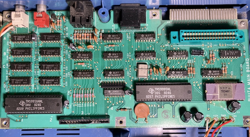
There are not a lot of support ICs on this thing, and they are all 74s. No gate arrays here2 – just a TMS9995 CPU, TMS9918 VDP, some decoding logic, a gob of DRAM for the 9918, and a ROM. I guess the 9995 must really reduce the amount of parts you need for a working computer. This feels very, very cloneable.
Fix the Keyboard
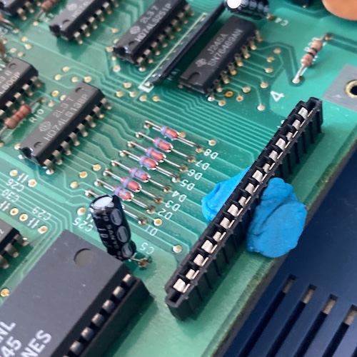
There’s no way that J-2, the keyboard membrane connector, is ever going to let go of its prize without a fight. Even if it did, I’d never trust it again. Its pins looked corroded, and the membrane tail had even been folded under a couple of the pins. After taking some quick measurements, I determined it was a 1x16 0.1” connector, and set about trying to find a replacement. That replacement was found in a TE AMP 6-520415-6 connector, which seems to be basically the same part.
In a perfect world, I would be able to magic up a brand new mechanical keyboard, but I hoped I would not need to do that. The remainder of the keyboard’s tail was still super-long; I figured I could do the same thing that Spectrum owners do, and shorten the tail a little bit to plug it right back in.
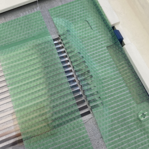
I stuck down the ribbon on the back of the keyboard plate, and then cut it with an art knife. I didn’t get the cable completely flattened out, which meant that the cut wasn’t perfectly straight, even though I used the tape as a fence. Still, what’s done is done.
The contacts are exposed for the whole length of the ribbon, which makes cutting this easy; I was worried that I’d have to peel back some outer layer of plastic first. I did reinforce the tail with some kapton tape, both to keep it from fraying and to give it enough strength to push into the new connector. Since the cable is slightly shorter than before, it was difficult to install it. I had to choose between seeing what I was doing and putting my hands in the right location.
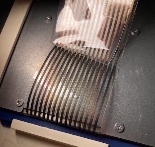
I have a feeling I may be back in here soon anyway to replace the keyboard. Not only is the main plastic housing of the ribbon very crunchy, but the strips of contact material have turned many pretty colours from the heat of the system, and seem to be corroding.
Did the replacement keyboard connector and ribbon butchery return the keyboard to functioning status?
Fix It Again, Tomy
Yes – to a certain extent. Almost all of the keys were now functional, except for the third and fourth column of the keyboard. This is still a massive improvement over how it was before, and now I can at least start software. Hooray?
While I was testing, I also noticed that I must have hooked the power LED back up backward, and as a result it was no longer lit, being a diode and all. Yet another reason to open it up again.
From looking at Enri’s schematics of the TP1000/mk1 Pyuuta, the third and fourth column of the keyboard are driven by pins 9 and 10 of the J2 keyboard connector. Those pins are in the middle, which makes sense to have not made great contact.
After opening and wiggling the cable a little, I now had everything working, except for the column with the “9” key on it. I opened the system a third time, while it was running – a little sketchy, with the mains power supply right there – and wiggled the cable some more. This solved the problem, although I definitely have a couple of false presses and sticky keys from the membrane itself still.
Hooray, a working keyboard! In all this excitement, I forgot to flip the LED connector wire back over so it would work, but I’m not exactly waiting in line to risk messing with that keyboard cable again. It’s good enough for now!
With the keyboard fixed, it was time to enjoy the machine.
Now for a game
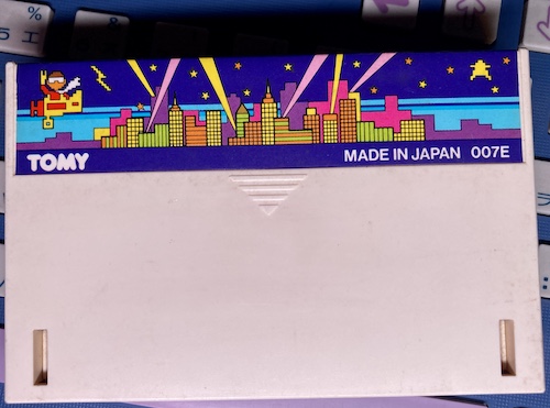
Once I realized the machine’s BASIC was a little limited, I rapidly availed myself of a Japanese-market videogame cartridge. From Mr. Kaiser’s thorough descriptions of Pyuuta/Tutor games and the available stock on Yahoo! Auctions, I decided I would select a game called NightFlight. It’s compared to Qix, and I really like Qix… for a little while, at least.
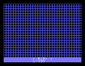
When a cartridge is inserted, the main menu of the system changes from “GRAPHIC/G-BASIC” to “GRAPHIC/G-BASIC/CARTRIDGE.” This is similar to the TI-99, although I note with some disappointment that – at least for NightFlight – the Tomy doesn’t pull the name of the cartridge out of the ROM, and display it in the menu, like the Texan machine did.
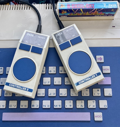
Also similarly to the TI-99, the Pyuuta “joysticks” are two controllers wired into a single DE-9 connector. They have a generally awful feel, and are a little bit too small and lightweight to fit comfortably in the hand.
I tried a round of NightFlight, and immediately ran into an issue. Pushing right on the “player one” controller didn’t make my plane go right.
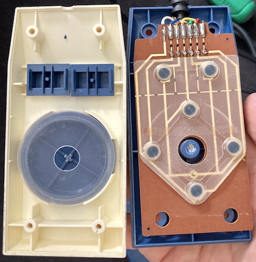
The obvious thing to do was to take a break from NightFlight and dismantle the first controller. Inside, you find a rubber membrane with conductive pads over top of a (gold-plated?!) single-sided PCB. As with the rest of the system, the plastics here are top-notch, with very little distortion or cracking even though they used self-tapping screws. Clearly, Tomy, a company that mostly makes cheap plastic toys, had their plastic design standards down pat.
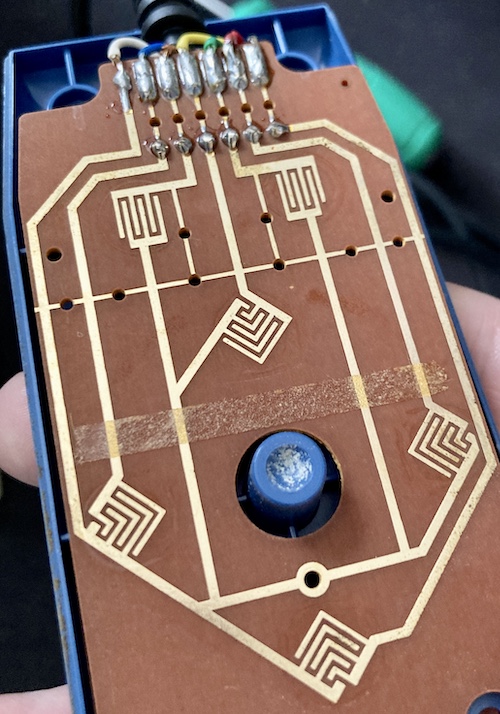
You can see here that a strip of adhesive used to hold the membrane pad onto the PCB, because otherwise it falls out when you turn it upside down to put the two halves together. I took the membrane pad out and scrubbed the conductive pads on a clean piece of new printer paper, until there was no longer any glossy varnish on their surface. I also wiped the gold traces themselves down with some isopropyl alcohol on a q-tip, which picked up a very faint kind of yellow stain. I’m not sure what that was.
Slap it back together, and…
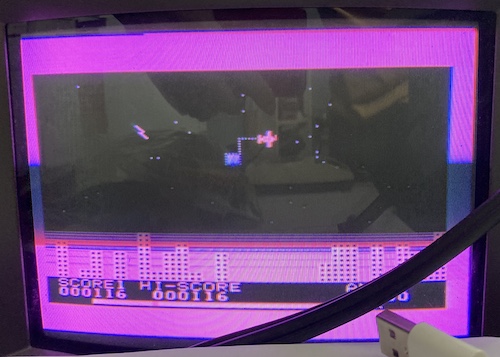
It works – now I can fly in any direction I want! I had no idea how to complete squares, and kept getting killed by enemies and then failing to catch my parachuting pilot. Neither touching the walls, nor crashing into my own wall seemed to do anything to complete the square. I ran off and looked for video on YouTube, where it was revealed that the secret appears to be to complete a loop containing the original square’s vertices. Amusingly, if you close up a huge region, the game says “I am computing now!” while you wait for it to finish figuring out how much of an area it has to flood-fill.
Basic Japanese BASIC lessons
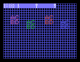
To make sure I did a good job, I took a break from NightFlight to write a quick program to test the joysticks.
Based on Cameron Kaiser’s GBASIC keyword listing page, I determined that I would have to write the following English GBASIC program, which I am grateful to him for providing:
10 PRNT 1,"STICK 1"
20 PRNT 33, "STICK 2"
30 KEY 1 A,B
40 KEY 2 C,D
50 PRNT 8, A
60 PRNT 16, B
70 PRNT 40, C
80 PRNT 48, D
90 GOTO 30
100 END
Of course, that’s English GBASIC, for a Tutor or a Pyuuta mkII. I had a Pyuuta, so I’d have to figure out the Japanese.
In GBASIC, Japanese keywords are entered in katakana, which feels a little weird to use for Japanese words, as usually I see katakana being used for loanwords from English and other foreign languages. No doubt Tomy was running into memory constraints, and decided to go for whatever they could fit into the TMS9918’s limited 256 entries of pattern table memory most efficiently, rather than implement keywords in hiragana (kanji is right out of the question for 8x8 tiles, I suspect.) Don’t forget they were forced to be sharing that video RAM with, well, program RAM!
That involved a visit to an archive of Junya Kubota’s Japanese GBASIC keyword listing, where I figured out what the magic KEY commands were for joysticks.
| English keyword | Japanese keyword | Notes | English keyboard equivalent in MAME |
KEY |
キイ |
In Japanese, the word for a lock key (かぎ) is different from a computer key (キイ) |
G, E |
PRNT |
カケ |
T, " |
|
GOTO |
ニイケ |
This is used in the verb-form – I think – so the line number in Japanese is a prefix | {number}I, E, " |
END |
オワリ |
6, 0, L |
|
GBAS |
GBAS |
Launching GBASIC is the universal language. | English Shift + G, B, A, S |
GRUN |
ジッコウ |
D, graph shift + -, Z, B, 4 |
So, I reasoned, the converted program should look something like this:
10 カケ 1,"STICK 1"
20 カケ 33, "STICK 2"
30 キイ 1 A,B
40 キイ 2 C,D
50 カケ 8, A
60 カケ 16, B
70 カケ 40, C
80 カケ 48, D
90 30ニイケ
99 オワリ
Phew. How do those United Nations interpreters keep up with this kind of workload?
To figure out the workflow, I took a practice run in MAME (with the pyuuta driver), where I couldn’t figure out how to do English-character shift until I remapped the “shift lock” control away from the caps lock key of my Mac.
After finishing the painstaking entry of the program, I was again foiled by trying to figure out how to type ジッコウ (jikkou, or “work,” the apparent equivalent of GRUN) – I couldn’t figure out how to type a diacritical mark, or the small katakana ッ.
Checking the real keyboard filled me in on how to enter a diacritical mark – it’s entered by the other shift key, which otherwise does quote marks, etc. It’s up in the top right, along with the little bubble one that makes ぴ in hiragana. As for the small ッ? Just write a big ツ. Do you think even Tomy, at the height of their powers, could make that baby tsu legible, writing it into an 8x8 tile on an NTSC composite display?
I ended up doing this entirely in the emulator, because the keyboard was getting flakier and flakier despite my attempts. Removing and re-seating the ribbon was visibly flaking off carbon, and even when I got a good connection, it would begin to degrade as the system heats up. This is a pretty disappointing end to the story, but check out my made-in-MAME masterpiece:
This whole experience has made me realize just how English-dominant we expect computers and programming languages to be, even in our modern era of Unicode and Google Translate. It is a big, frustrating, impediment to folks who don’t speak English learning to write software!
Conclusion
So that’s the first-generation Tomy Pyuuta: a true oddball, even among Bubble Era Japanese toy computers. I think after experiencing it for just a little while, I now better understand its appeal, and I definitely get why the mkII/Tutor/Jr made such a departure from the original model to try and save the platform.
Now that I’ve crudely lashed this poor Tomy back to life, and even (temporarily) fixed the parts my impatience broke, what’s next to do?
Obviously, first is to figure out a better repair for the keyboard. I’ll try more heroically to pry it out of the case, although that trapped wire keeps the clips from flexing enough to do so. I would love to keep the original keys, since some of them are very unique to this system, and go to something like a Kailh Choc mechanical switch behind it (like the PC-6001mkII aftermarket keyboard PCBs.) Of course, the fragile acrylic ribbon would have to go, and be replaced by a saner 16-pin pin-header connector on a ribbon cable. This is, however, a very large project that involves lots of measuring… and I’m not up to it right now.
In terms of upgrades: with such a simple computer, there’s lots of options. For one thing, I would like to replace that antiquated mains power supply (and its glitchy power switch) sooner rather than later, since I don’t want it to brown out and damage sensitive RAMs in the future. There’s maybe even enough room inside the case for something based on USB-C Power Delivery.
To make the computer more useful, I’d like to find some information about the guts of the BASIC-1 expansion module, which gave the mk1 Pyuuta the more advanced (and English!) BASIC from the mkII/Tutor. It might just be as simple as a ROM and some decode, and an open-source version could make mk1 Pyuutas all over the world more useful!
And last, if you look at my AliExpress order history, you’ll notice that a TI TMS9995 CPU has made its way to my home recently. After looking at the mk1’s simple motherboard and the rest of my parts pile, it would just be a shame to not make a clone of this one, too.
Repair Summary
| Fault | Remedy | Caveats |
|---|---|---|
| Does not reliably power on, and browns out during normal function. | Clean the rusted spring inside the power switch, and clean burned contacts to make good contact. Lubricate. | Likely to fail again in the future, as metal has been eaten away. A good long-term solution would be to replace the power supply with something modern, and substitute this power switch for a low-voltage, logic-based wake-up one. Also, a reset button would be nice. |
| Power LED cable caught in the keyboard mount in the top panel, preventing the case from being opened. | Snip power LED cable and splice it back together. | Still no idea how to get it out, or remove the keyboard without excessive force with it pinned together like that. |
| Keyboard membrane tail caught in the connector and broke. | Cut back membrane tail, replace connector. | Contacts on tail look oxidized, which threatens an unrepairable membrane failure in the near future, and it’s scratchy when it does work |
| Controller 1 won’t fly right. | Dismantle joysticks, clean conductive pads on membrane using clean sheet of printer paper. |
-
Many high-end power supplies add an anti-arcing cap in parallel to the contacts of the switch, known as a “snubber,” to suppress this phenomenon. It is probably too late for this switch, but I looked into it briefly. Surprisingly, the Cornell Quencharc family of film caps seems quite expensive! There is probably a cheaper solution, as I can’t imagine high-end stereo manufacturers are eating $18 per unit to protect a $1 power switch. Maybe the cheaper solution is what basically everyone is doing, which is to simply make mains-interrupting power switches a thing of the past. ↩
-
The mk2/Tutor adds a little more logic, as it has a significantly more complex memory map. For instance, there’s banking logic to switch the cartridge out of CPU memory space, and substitute it with the enhanced mk2 BASIC ROM on the motherboard. ↩