CoCo1 composite video
Tags: computer tandy coco video mod homemade-hardware
When I got the CoCo, one of the big problems was the super-smeary, snowy video on the RF-out. Even though composite video is generated internally by the video circuitry of the computer, Tandy didn’t end up breaking it out to an actual port. Lots of other 8-bit machines of the era are in the same boat. Luckily, adding a composite video port to the CoCo is very straightforward! So straightforward, in fact, that I did it twice.
Theory
As I said just now, the Motorola 6847 VDG already generates a composite video signal (by way of the MC1372 modulator transforming it from something-like-YCbCr into composite) and sends it to the RF modulator, which encodes it and the sound with the channel frequency. This is accomplished through some kind of fancy radio math that is scary, but thankfully I don’t have to understand it.
This RF signal is transmitted into the antenna input of a television set, and then you can tune into channel 3 or 4 to watch your CoCo work. There’s a great explanation of how RF video encoding works in this now-classic Cathode Ray Dude YouTube video about NES RF, including some inadvertent operation of a pirate TV station.
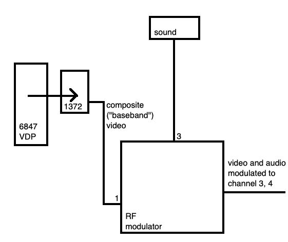
Since I already have composite coming out of the internal chips, I’ll just snipe it from where it comes from and get it to the TV directly. Easy, right?
This project started in 2019, which you may note is not the current year. This is one of those projects that has taken me a really long time to get to this point.
Discovery
My first step was to see if someone else had made a composite mod. Composite is ‘good enough’ for most of my old computers; I have a lot of composite monitors and TVs lying around the place, and it’s probably fairly future-proof. Even new LCD TVs sold at Walmart still have an AV jack in them, and cheap AV-to-HDMI adapters will probably keep existing until I’m in the ground.
There is the amazing CoCoVGA 6847 replacement, but it’s quite a bit of money to spend on a CoCo that doesn’t even have a working keyboard yet. Plus, I know how I work. It would probably end up getting used in one of the PC-6001s anyway.
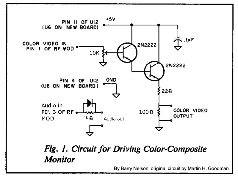
I found this circuit on Hackaday’s community portal, done by Barry Nelson. It’s an enhancement of a circuit from 1983 designed by Martin H. Goodman.
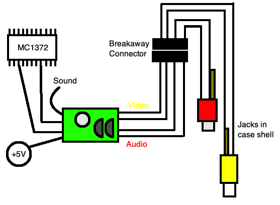
My theory is a little thin, but the two 2n2222 transistors in the middle seem to form a Darlington pair - a common design for an el-cheapo amplifier. From what I can tell, this takes the attenuated composite-video signal from the 6847 (on pin 12) and beefs it up so it can provide enough current to satisfy the demand from the television. Then we take the beefier composite video signal, and put it out on some RCA jacks. Thanks, transistors!
This output-level amplification is one of the services provided by the THS7374 chip used in my rough Famicom composite video mod. I thought about reusing that board – I had plenty left over – but I figured following this design might teach me something.
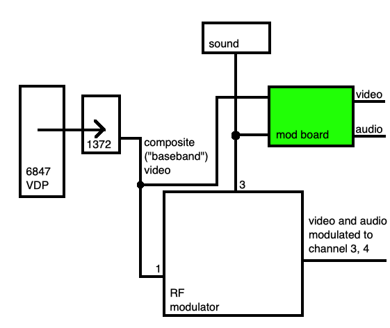
U12 in this diagram is not the 6847. You may recall from an earlier entry on the CoCo that the 6847 has a little friend called the MC1372P video mixer, which takes the raw chroma(e) and luma signals from the 6847 and mixes them into composite video.
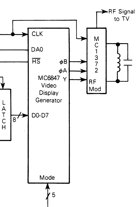
It’s really nice when the datasheets provide me with a diagram. Remember that composite video is really the base signal for what we call “RF-out;” it just hasn’t been put onto an actual channel yet. The RF modulator box on the board still needs to take that signal and mix it into a TV channel (3 or 4) so the TV can understand it.
I started off doing this circuit on a protoboard, but then I wasn’t pleased with how it looked. At the same time, I was already sending off a very large order to JLCPCB, so I tacked it on the order.
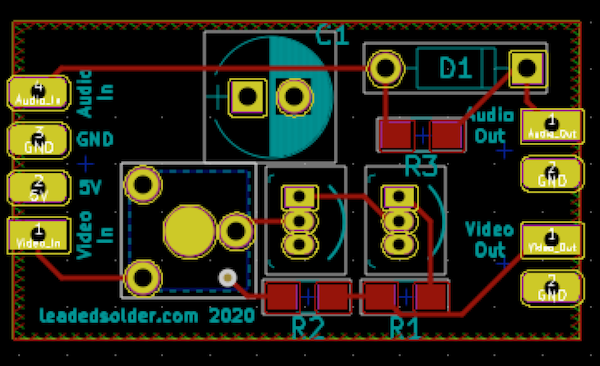
I could definitely have made this board much smaller. The 10k fine-tuning potentiometer and the massive footprint for a measly 0.1µF capacitor are the dominant elements. Even so, the resulting board is still so small that it was easy to panelize a bunch of them and send them out for order.
Dechunked
The panelization was pretty cool! I got back five boards that had been scored, and I could snap them apart into little boards. Each of the five ‘big boards’ carried 12 little boards on them, so I ended up with a total of 60 CoCo composite boards. One or two were damaged in manufacture (scratched) and JLCPCB refunded me for them before shipping them out.
After a few minutes of snapping apart boards on my kitchen table, I had a soup of PCBs and a CoCo composite board to work on.
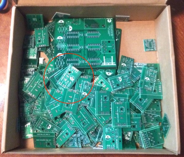
There were actually a lot of different boards tacked onto this order. Don’t peek too closely! You’ll spoil future projects. Err, past projects. Maybe a little of both.
After a few minutes of surface-mount and through-hole soldering, the first test board was assembled. I realized a little late in production that I didn’t have any 0.1µF electrolytic capacitors on hand, so instead it got one of a pile of 0.1µF unpolarized ceramic caps from my hoard. Oh well, it still looks… alright, if a little weird.
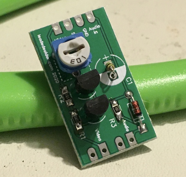
If I had thought ahead, I would probably have remembered that I had a ton of 0.1µF ceramic surface-mount 0805s and could have easily put them in alongside the three resistors. Don’t look too closely at the soldering job on those surface-mount resistors, either. I’ve gotten slightly better at this since then.
Installation is the Reverse of Removal
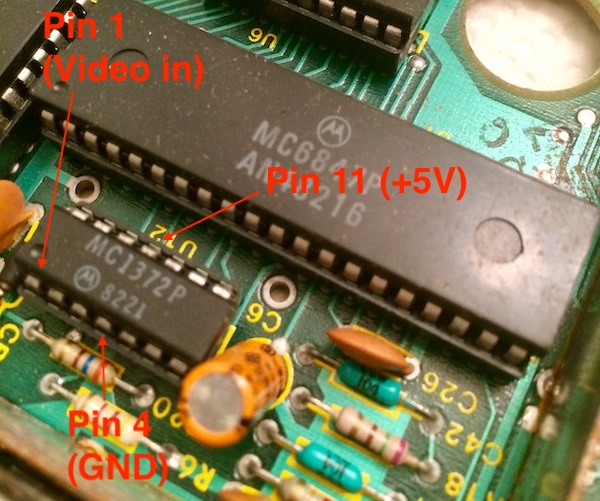
My plan was to solder the new AV-mod board right to the MC1372’s legs. Normally, I wouldn’t do this, but the 1372 is a very common part - replaceable for $2 on eBay - and it’s unlikely that the modification will need to be reversed. Plus, the board is hardly original, between the keyboard mod and the 64K RAM upgrade. If anything, I figured I was only following in the footsteps of the original owner.
The break-away connector was intended to make it easy to remove the top case for future service/mods without having to desolder anything. I left my lines long, in case I wanted to try other video boards later.
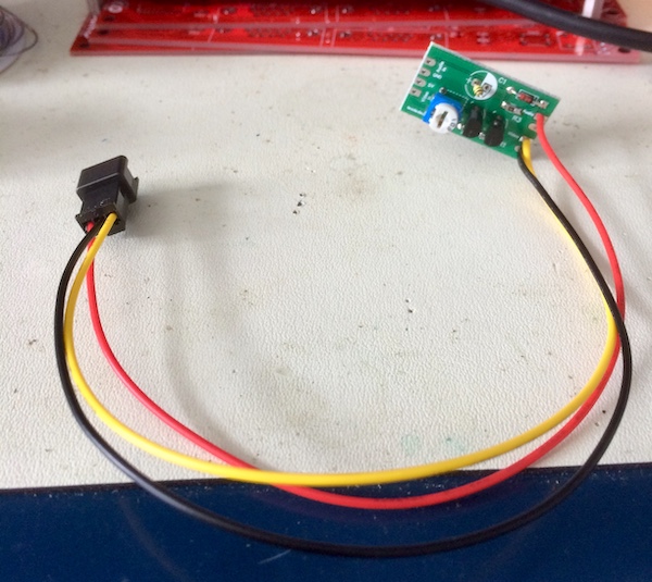
I have had no luck crimping JST-style connectors like this, but then I ponied up the cash for an Engineer PA-09 crimper. This one came with a little manual that actually explained how to properly size and align crimps, and it produces great crimps every time. Definitely worth the money.
Since I only had 3-pin connectors on hand, the audio and the video will have to share a ground. This is likely to cause signal degradation, but I think that I’m already not working with a perfect system:
- Neither the CoCo video or sound hardware are particularly high-fidelity;
- The entire circuit only has one ground back to the CoCo, which is only partially mitigated by the ground plane on the mod board;
- I’m running a bunch of loose wires past an 80s power supply and hoping that the plastic insulation on the wires will do anything at all.
There are a lot of changes I could make here for better signal integrity, but the important thing is making sure it works at all.
Wiring to the Chip
Now things went off the rails. It was time to modify the CoCo itself. First, I’d have to connect the composite mod to the motherboard, which I don’t mind doing, but then I’d have to drill a few holes. My track record on drilling holes is not especially great, and it’s here that I got cold feet.
In order to get my video and audio out of the CoCo1, I’d initially decided to add RCA jacks to the exterior of the machine. I have seen some other mods where they leave cables dangling out through the case, but this looks shabby to me and is likely to get broken in future years as the machine is stored and retrieved.
Here’s the controversial part: in order to add those RCA-style jacks, I will need to drill two holes in the case for them to mount to. Normally, I’m a big fan of preserving the machine as it is, but this computer has already seen a lot of modifications and the case plastic is not in good shape. There is not much purity left to salvage.
The case has worn-off paint, lots of cracks, the original owner’s name scratched into the bottom of it, and a missing chunk of plastic. I talked myself into believing that I wasn’t not doing any further harm to the historical value of the machine by adding my own jacks, as long as I did a good job of it. Whoever modified this machine in the first place started writing the story of this computer, and I’m just adding another chapter. I’m positive the original owner wouldn’t have blinked at doing a similar modification.
My plan for drilling the holes was as follows:
- Make some kind of a drilling template that can be affixed to the case so that the holes are level;
- Drill a pilot hole to align for the big holes;
- Drill real holes;
- Button up the RCA jacks and solder up the female side of the 3-pin connector;
- Figure out how to load Temple of ROM on this thing.
Making the template is a good place to start. I first measured my RCA jacks with a caliper to make sure I didn’t make a hole that was too loose or too tight. From what I can understand, there’s not a lot of consistency between suppliers, so it’s always worth checking out the footprint of parts that you have in hand first.
From there, I produced a little KiCad PCB file with all the measurements, and printed out a few copies of it to use as a drill template.
Change of plans
As I often do, I got cold feet around the time it came to actually drilling a hole in the CoCo. I let it sit for years; adding composite video turned out to actually be a six-year project.
What spurred me on was that I decided to show the CoCo at a local get-together. I wanted to demonstrate the new mechanical keyboard, and the FujiNet adapter. Showing off the CoCo’s fuzzy RF would just take away from the effect, so it was time to finally get off my butt and install that composite video board I’d had lying around on my desk for years.
Or… I could not do that?
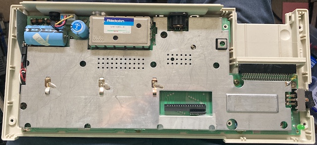
While I was looking over the CoCo’s motherboard, I realized something. That Astec RF modulator, the UM1285-8, seemed very familiar. In fact, it seemed to be the same exact RF modulator as used in the Mattel Aquarius.
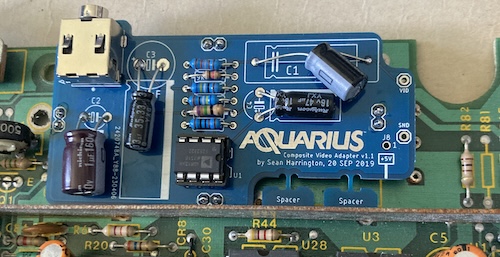
I have four of Sean P. Harrington’s boards left over from when I AV-modded the Aquarius, along with a bunch of spare passives! Score one for hoarding.
Putting together the Aquarius AV board
Not all was fine in hoard town, mostly because I only bought singles of the most expensive parts from the last time around. Analog Devices was nice enough to send me another sample AD812ANZ amplifier.
I certainly did not buy more than one axial 2µF electrolytic last time, as they cost nearly eight dollars. Instead, I rooted through my radial 2.2µF electrolytic supply, and metered them all until I found one that was close to 2.0µF – most of them read much higher!
Of course, I still couldn’t get out of this without placing an order: the TRRS jack is a little special. None of the ones I had on hand fit, or weren’t TRRS, or both. When it arrived, I soldered it down, and then prepared to load the board into the CoCo.
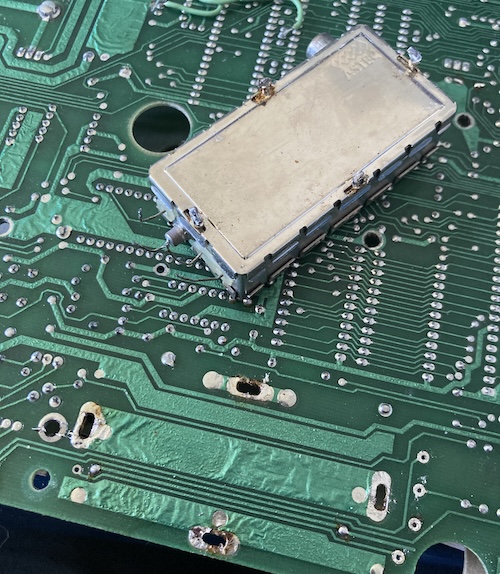
Removing the RF modulator is not super hard. What it is, is annoying. Tandy bent the legs on the RF modulator when putting it in, so you have to not only remove as much solder as possible, but also bend the legs back straight without tearing a pad. I was… mostly successful at this.
Before soldering the new board down, I took a quick look at height. The Aquarius board requires some shims, because it needs to be placed a little closer to the board than usual so that the port is “centered” in the hole on the Aquarius case. This is not a problem on the CoCo, because the hole there is arch-shaped, and there is plenty of room for cable shenanigans. Still, I’m glad that I checked before soldering down the new board.
My next obstacle was that the “vid” and “sound” holes on the motherboard did not line up exactly with the holes on Sean’s Aquarius board, probably because the Aquarius has slightly shorter wires coming out of the RF modulator. I stuck some magnet wire through and made that work, although it was some tight, stinky work burning the insulation off. It was verified with the continuity mode on my multimeter.
For the +5V required for the Aquarius composite board, I rooted around with the very same continuity mode until I found an axial capacitor whose positive side appeared to be connected to +5V. Then I wrapped its positive leg in wire, soldered that wire down, and ran it to the composite board’s +5V input pin. Not clean, not pretty, but a solid connection that won’t come free any time soon.
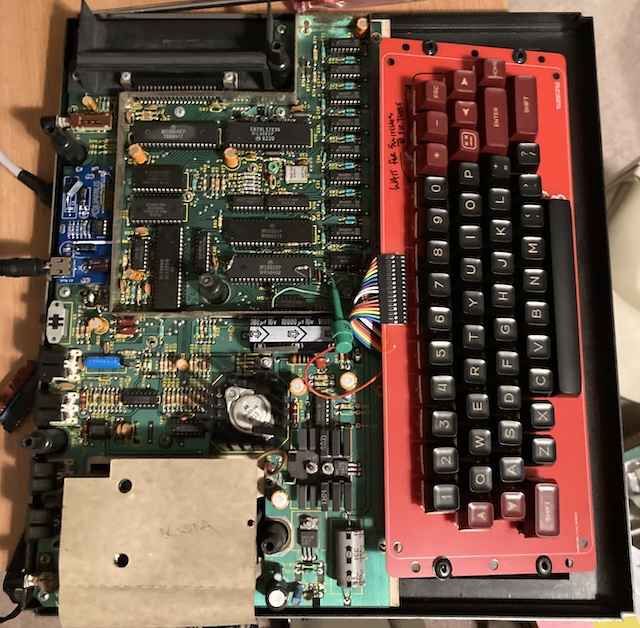
Man. Look at all those new boards and bodge wires in here. This thing has been modified.
Test it
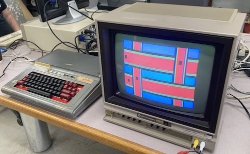
I went to the Aquarius on the shelf, which still had its “Sony-pinout” TRRS AV cable connected, and helped myself to its video cable. After some preliminary re-assembly of the CoCo (that transformer has so many connectors!) I was able to get it roughly on the desk and ready to test with my somewhat un-trusty Samsung 910MP LCD.
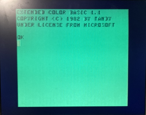
Success! It has reasonable colour and legible letters, and looks a lot better than the snowy RF already. That slightly smeary text doesn’t look pin sharp, but that’s hard to accomplish on the 6847 without S-video. And if I’m going to go to that much effort to add S-video to a 6847 system, it’s going to be one of my beloved PC-6001s.
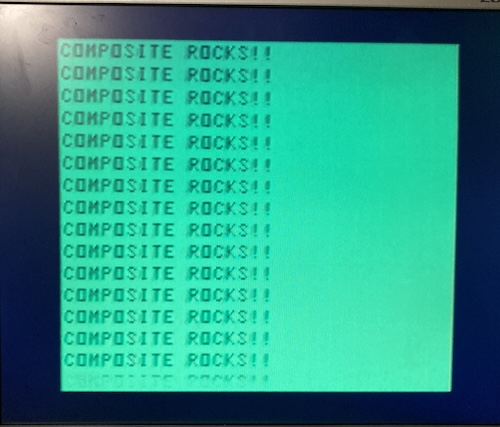
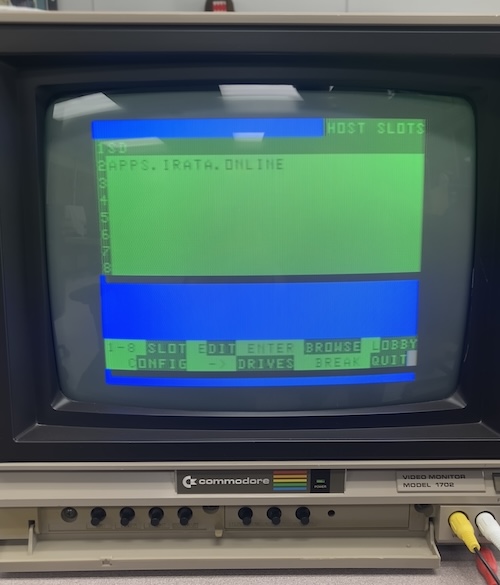
But wait: what if it’s just the fault of the hated enemy, liquid-crystal displays? Could a twenty-cent upscaler IC be lying to me about how good CoCo-originated composite video actually is?
Oh. Yeah, that’s way better. Screw you, LCDs! You make games look weird and you probably cause mad cow disease, too.
Text is pin-sharp, despite what this photo tells you. I bumped the camera while I was taking a long exposure shot. Tripod? What’s that?
Conclusion
While it’s not perfect, I’m really happy that I was able to put this composite mod together in the end. It’s even better that it was built using a board I already had extras of!
So if you’re one of the, oh, six or seven people in the entire planet who has both a Mattel Aquarius and an early Tandy TRS-80 Color Computer, you too can benefit from the research that went into this silly project. For the rest of you, well, maybe try something else. Like buying an NEC PC-6001, which already came from the factory with composite video.