Building my own ArdSCSIno
Tags: computer homemade-hardware apple
A lot of newer computers need what is called “a hard drive,” and as I work on 16- and even 32-bit ones, I’m finding more need for SCSI drives. There’s already lots of great SCSI emulators out there, but how do they work? And more importantly: could I make one cheaper?
Long-time readers will remember I’ve used a lot of BlueSCSIs for various shenanigans around the home. These things are great: they’re inexpensive, open-source, and well supported. While it’s undergone a lot of tweaks and at least one platform port since, the original BlueSCSI firmware is based on the ArdSCSIno, a Japanese open-source hobbyist project.
The ArdSCSIno is what it basically sounds like: using Arduino-compatible microcontrollers (which have gotten extremely fast for extremely cheap thanks to parts like the STM32-based Blue Pill board) to emulate a SCSI hard drive in software. It sort of blows my mind that this is even possible, but a 72MHz ARM (even faster with overclocking) is probably a good integer multiple faster than even the fastest 68k Mac.
Before we begin, primary credit for this project goes to ztto, the designer who made an STM32 Blue Pill version of the original ArdSCSIino setup, which was itself originally developed by Japanese hobbyist h_koma2. I’m using ztto’s pinout, and documentation. The only effective difference from their board is that I am just adding optional termination resistors (more on why in a bit.)
I had a couple Blue Pills lying around the house from previous aborted projects (some of which are keyboard converter projects, naturally) so I already had gotten over the big hump that is figuring out how to program the damn things.
Originally, I thought about building a whole bunch of BlueSCSIs instead – just order 10 copies of the Gerbers and then start stuffing them. But at this time1 (2021,) the BlueSCSI project was brand new and getting the Gerbers was only by request. Aside from the (ultimately unjustified) social anxiety, I figured I would learn more from actually reading the ArdSCSIno schematics and firmware, and getting to know how it all works. I’ll take any excuse to make a board.
Also, I wanted to do some custom PCB layouts for weird computers, but we’ll get to that in a later entry.
Initially, this board was unnamed; the repository was just named ardscsino-fork. After it became obvious just how cheap this thing was to build, I promoted it to “Dirty ArdSCSIno.” I think it has a bit of a ring to it.
Design
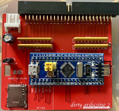
I didn’t see much in the original board to improve on; there are basically no components, and all the magic is inside the software. Like the BlueSCSI-v1, I wanted to add passive termination to the ArdSCSIno base. That’s what those big resistor networks are for. Initially, I had a jumper to disable termination entirely, but I decided that if I ended up with a situation where the ArdSCSIno wasn’t the last device on the bus, I’d just desolder the resistors.
The original ArdSCSIno is powered exclusively through termination power, which is the five-volt rail provided by the computer to serve as the “pull-up” voltage for the termination resistors. However, not all SCSI/SASI computers actually provide termination power (e.g. the early-SCSI Mac Plus, the late-SASI X68000) and the termination power wire on the ribbon cable is very long, very noisy, and very thin.
To fix this problem, I wanted to add an auxiliary header for injecting power directly into the board, which could be done with a standard SCSI-hard-drive-style Molex 8681/AMP 641737-1 connector. However, the “hard drive Molex” is a very large connector, and it dominated the PCB. I ended up going with a Berg connector footprint (TE AMP 171826-4) for the first revision, both because I expected I would be using termination power on my test Macs, and also because I would waste less board space if I didn’t populate the connector.
Last, I also wanted to add some mounting holes. Keeping the PCB tiny is a noble pursuit, but sometimes you just have to add a few cents to the build cost in order to be able to zip-tie your board to the case. Wouldn’t want this bouncing around and touching things it shouldn’t.
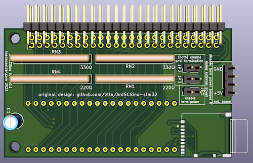
The result is that the new board looks basically the same as ztto’s board, but with some big chunky resistor networks hanging out. I really like the look of resistor networks, as obsolete as they may be…
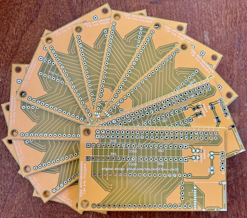
I got 13 boards for the price of 10 (which is really the price of 5 – for boards this small at PCBWay, “10” is a no-cost upgrade); a good deal.
Although prices have gone up across the board, at the time the bill of materials only cost $13.18 Canadian per unit. That’s a pretty cheap board! Too bad prices didn’t stay that way.
Blue Pill Pricing
In the time since I did this original math and when I was able to publish this article, Blue Pill prices have nearly quintupled, which makes this PCB a lot less economical. The STMicro Cortex-M3 at the core of the Blue Pill is a very versatile and inexpensive ARM microcontroller, so it was in huge worldwide demand at a time where production was (and is) very constrained. It might make sense to fork this project further and look into using something like an Artery ARM microcontroller instead of the Blue Pill; the Gotek manufacturers already did.
Some good friends of mine have looked into the GD32-based clone STM32s, but they reported a ton of problems with things as basic as “programming over USB” and “programming the damn things twice.” Hopefully the toolchain and quality issues get worked out over there, or they just got an especially bad batch.
Maybe the thing for me to take away from this whole episode is not to count my chickens before they hatch. This whole thing is why I usually try not to add up the costs of projects at any given time – any pricing will change from month to month, especially in the current environment of random shortages, wacky tariffs, and price hikes. Also, the sheer cost of some of these projects will just depress me.
So, cheaper? Yes. Better? Well, so far it doesn’t work. Let’s see if I can make it work.
Finding Out
One thing that I learned about SCSI as part of doing this project is that it has actual pins that do specific tasks, and a human being can make devices that interact with those pins. I’m not sure why I had such a mental block when it came to understanding SCSI; I think I got intimidated by all of the super fast new stuff that came after 8-bit narrow-mode SCSI. There’s also not too many large fixed disk projects in the community to learn by osmosis from, unlike, say, floppy disk drives.
I waited patiently for the demo boards to arrive. A handful went off to a friend, Chartreuse, who helped me with the Leako project. We hoped that we would be able to build these, get them working, and then explore some freaky new stuff like CD-ROM emulation and replacing the Blue Pill with a higher-clocked Black Pill STM32 board for faster transfer rates. All of that didn’t really happen. In the meantime, the Pico-based BlueSCSI-v2 came out. It’s so significantly faster and more capable that those goals quickly became obsolete.
In fact, I just bought a BlueSCSI every time I needed one, and never actually ended up building one of these yellow menaces.
That’s when I ran into another shortage. My preferred BlueSCSI vendor, Drake over at BlueSCSI of Canada/BleuSCSI du Canada, had trouble sourcing parts to make more BlueSCSI-v2s for me at a time that I needed one. You saw how that worked out in the triumphant (and smoky) recent SPARCstation entry.
After that project was done, I thought some more about this project. I still had a need for more SCSI emulators in the future, and still had a small handful of Blue Pills that I managed to collect when they were slightly cheaper than they are now. So let’s throw together one now.
Lookin’ good.
While waiting for the handful of parts that I had inevitably forgotten or used up in the interim, I asked Eric Helgeson, the developer of the then-new BlueSCSI project, if I could use the BlueSCSI-v1 firmware with my sketchy board. He had no problem whatsoever with it, and even helped with a bunch of my dumb questions as I was setting up the board. Thanks!
I used my STLink-V2 clone and whatever version of the open-source st-flash command line tool was still installed on my Intel MacBook Pro from way back in 2015 to write the BlueSCSI.bin firmware file from the BlueSCSI repository. It was written at address $08000000 , like on the BlueSCSI flashing directions.
Mac Test
Obviously, the easiest thing to test with BlueSCSI would be a Mac. I grabbed an SD card out of my pile, wiped it using the SD Card Formatter utility, formatted it for FAT32, and then dropped on an OpenRetroSCSI System 7.1 disk image.
I plugged it into my sorta-working IIsi, and fired it up on termination power only. I didn’t see any LEDs light up on the Blue Pill, and the Mac was unable to find any boot device.
On my PCB, I had clearly connected termination power (pin 26) to the +5V rail of the Blue Pill, and the multimeter agreed. But with the voltmeter, I was seeing less than a hundredth of a volt on the external power connector.
It turns out that the Mac IIsi was a terrible choice to judge termination power.. because the Mac IIsi doesn’t produce sufficient termination power. I’m a little grumpy that I burned a good hour of shop time on this, but luckily I have many other SCSI-equipped Macs to grab for testing.
The next choice was the Bad ADB Mac LC, which is enjoying a comfortable pseudo-retirement being used as a victim for all kinds of things like this. No, it’s not elder abuse, you’re elder abuse. It loves it.
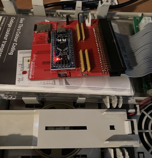
I knew that this doddering old LC had working SCSI termination power, which would make hooking this mess up really easy, so I pulled out the hard drive inside it and jammed the ArdSCSIno in its place.
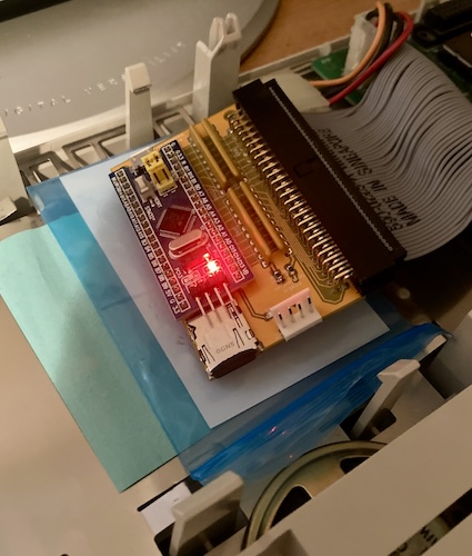
This time, the lights on the ArdSCSIno turned on. They pulsed. Things happened deep inside its silicon maze. But the LC refused to boot, dutifully popping up a question mark disk after many seconds of waiting for the SCSI bus to get its act together.
After all this, I noticed that the ArdSCSIno was repeatedly blinking the green light five times, which is probably the BlueSCSI v1 distress code for “no SD card.” Indeed, there was no log written to the SD card.
Having learned my lesson from the SparcStation 1+ termination power debacle, I suspected the power was simply too weak for the microcontroller and/or SD card to work.
I checked the power on the ArdSCSIno board and noticed it was only 4.14 volts, which is certainly less than five. Maybe I needed external power for this LC after all? Using a phone charger, I powered the Blue Pill off external micro-USB power. This didn’t change anything, though, and the five blinks remained.
Out of desperation, I tried a known-good SD card from my external BlueSCSI v1 build, and nothing changed. It was a bit of a relief to have it ruled out, but SD cards are a lot cheaper than diagnostics.
Paranoia sets in
As you do when you screw up the pinout a lot on new boards, I wondered if I had gotten the pinout right, and checked the BlueSCSI source code to make sure I hadn’t assigned the wrong pins anywhere. All the obvious SCSI pins were correct, but I found it hard to follow what pins the SD card interface was using, so I went on a dive picking through the BlueSCSI-v1 PCB designs.
Checking their schematic showed that I was using the same pins on the microcontroller, and the same pins on the microSD card. Somehow, I had even avoided mixing up MISO and MOSI. SD card detection should be working.
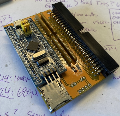
I decided to check if I had bad solder joints. Unfortunately, some idiot designed the board so that the Blue Pill partially covered the solder joints of the SD card module, making them impossible to probe without desoldering the 40-pin microcontroller first.
As a sort of nasty proxy for actually doing that 10 minute job and having a fixed board in the end, I chose to get scientific and first prove that I had bad solder joints. I decided to try and measure the resistance between those GPIO pins on the Blue Pill involved in the SD card, and ground.
My thinking was that with the card inserted, the resistance to ground on pins connected properly to the SD card should change – there’s additional paths to ground introduced through the circuitry of the SD card when it goes into circuit with the rest of the board. Any pins that don’t change in response to the card being inserted and removed would then, in theory, be likely to be indicative of a bad solder joint.
Pins A7 and A6 (MOSI and MISO) changed from 4.6MΩ with the SD card inserted to 5.8MΩ with the card removed. On the other hand, pins A5 and A4 (SD clock and SD select) did not change from 5.8MΩ at all!
It’s hardly a robust test, but it made me feel clever. Also, now I had a good reason to try and desolder the Blue Pill and see if the joints on the SD card module really were bad. Plus, I had a dim memory of soldering that SD card holder being a huge pain in the butt when I put this thing together years ago, so there’s no way it wasn’t bad.
Did I desolder the Blue Pill?
No, of course not. What I actually did was: order a whole second set of boards to try and make assembly easier.
Version two board
I wanted to make a new “version two” board for a couple reasons:
- The old board’s mounting holes were not compatible with anyone else’s mounting sleds. I copied the mounting holes from a few brackets I had lying around, so I wouldn’t also have to design and 3D-print some mounts.
- The power connector had a completely wrong pinout, but it used a Berg connector, so someone could possibly plug in a “regular” one from an ATX supply and fry it. I wanted to correct this as well; I’m a little sensitive to voltage mismatches in SCSI emulators as of late for some reason.
- I made the old board a little bit too small, which made it difficult to get in and out of the SCSI data cable, since I didn’t have enough leverage or a non-pokey place to grab it. Since I’m paying a flat rate for “anything under 100x100mm,” I just beefed it up a little bit.
- It’s too hard to double-check the SD card soldering when the board is assembled, because the Blue Pill gets in the way. I added a whole second set of SD card headers, meant for one of the “Arduino” SD card modules floating around AliExpress. Even if you don’t have one, you can use these pins as test points to do a continuity check. Then you can be sure all the SD card pins are soldered properly on the surface-mount holder.
This revised one hit most of my goals. It made it a lot easier to test the SD card (just using the Arduino breakout footprint as a test probe), although I still globbed up the SD card holder with inappropriate solder globs to the roof. To try and fix this, I made the pads a little longer in the next version, so it was easier to hit them with the iron and ensure a good fillet.
For the new power connector, I tried to use a right-angle Berg connector since one was lying on my desk, but it interfered with the SCSI connector. So I just.. trimmed it. That’s not my smartest move, especially because the cable still didn’t fit afterward. I desoldered it and put in a straight-up Berg.
It was also hard to solder in the Berg connector (pads too small on the Digi-Key footprint,) and an already-legged Blue Pill didn’t fit in the hole because it was super tight and therefore needed thinner legs. I ended up fixing both of these in the next revision of the board.
As for mounting holes… those ziptie holes also interfered with the debug header, and I accidentally deleted the mounting holes from the PCB when I sent the board to fab.
Still, I think it looks really good! I’d be proud to entomb this inside an old computer forever.
Flashing the version two board
Because I didn’t want to desolder the Blue Pill from the yellow board, I grabbed one out of my bin of parts and soldered it down to the board. Before flashing it, of course…
I ran into a problem here. Both BlueSCSI-Updater and QMK Toolbox failed to flash the Blue Pill over USB, claiming a LIBUSB_ERROR_TIMEOUT at 44%. This seemed to screw something up and require me to reflash the bootloader with the STLink every time. After checking with Eric, it turns out that I had a C6T6 STM32, and I needed a C8T6 – not enough flash.
I was pretty sure I checked these when I got them to make sure it had the right amount, but that’s life. I wish I had tried to flash this before soldering it onto the board, but that’s life, too. Digging through my microcontroller bin, I found a C8T6 clone board with USB-C.
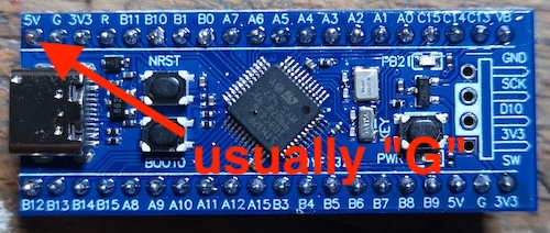
They also annoyingly added a 5V pin in the top-left corner, which on my board is expected to be ground, so I just didn’t populate that pin on the header.
The jumpers are also different, so I had to figure out an alternate technique to persuade the board to become flashable. I held the BOOT0 button while flashing the bootloader, and then pushed the nRST button when the BlueSCSI Updater was looking to flash the firmware over USB. This seems to have worked.
After pulling the old Blue Pill and putting this new, freshly-flashed one on, I fired it up only to find out that the status LED wasn’t blinking. It also didn’t bother writing a bluescsi log to the file, so the firmware seems like it was either not running or very mad at me.
I figured out the LED very quickly – this version of the Blue Pill also put the LED on a different pin, PB2, for some reason instead of the normal PC13 – and globbed an LED and resistor onto the backside so I could figure out what was going on. Five blinks meant “no SD card,” so I was essentially back to where I left off with the previous board.
Having done a lot of work and spent a lot of money to get to this point, I realized I was no longer having fun, and put this project back on the shelf for a bit. And by “a bit,” I mean about fifteen minutes, before I pulled it back off the shelf and started working the problem.
After an afternoon of confusion and logic-probing the board, I managed to determine that PA7 had somehow become severed from the MOSI line. I suspect that this happened when I desoldered the old Blue Pill. Maybe a pad was severed or folded over. No matter how it happened, I should have probably noticed it earlier – a fresh board from the JLCPCB box was just fine. A bodge wire on my now-heavily-reworked board fixed it, and suddenly BlueSCSI was detecting the disk images on the SD card and leaving behind a happy little LOG.TXT. Yes.
Does version two work on a Mac?
Coincidentally2, the Bad ADB Mac LC had just had its hard drive dumped a few weeks prior to all this testing, so I grabbed its disk image off my backup storage and then threw that disk image on the SD card.
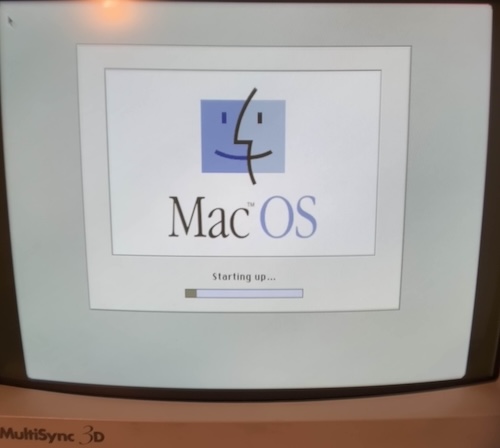
After some cable jiggling inside the LC, the Dirty ArdSCSIno booted the computer off that disk image like nothing had ever happened. It works!
What was the point of cloning it?
You might ask why I bothered to do all this, instead of just running off a few dozen BlueSCSI v1 gerbers, considering the BOM is essentially the same and that I’m running the same firmware on an identical pinout.
That’s a very good question!
To be honest, I’m not sure myself. I’ve spent more money doing it this way than I would have just using the existing design. However, I learned a little bit about SCSI (and a lot about the various mutations of the STM32 Blue Pill) going through this project.
Having an opportunity to look at the original ArdSCSIno code and hardware design was also beneficial. When things get quirky with weird 80s machines3, I’ll be able to understand better what the thing is trying to do.
Another real benefit of this is that, now that I have a working example, I can adapt it to new form factors. I can now build “built-in” ArdSCSIno/BlueSCSIs into the expansion cards for a variety of machines, producing a sort of modern-day hybrid SCSI controller/hard card.
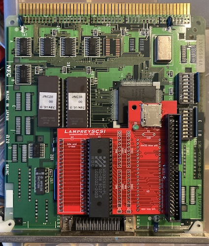
I have a couple machines in mind for this kind of support. Maybe you can figure out why there’s a Blue Pill footprint on this weird daughterboard on this PC-98 SCSI card?
Downloads
| Component | Download link |
|---|---|
| Gerber files | ardscsino-fork GitHub repository release page |
| BlueSCSI v1 firmware | BlueSCSI-Updater repository |
-
This project actually started as a low-cost alternative to SCSI2SD. How things change in just a few years. ↩
-
Projects tend to cluster into themes for me. This month, apparently the theme was “SCSI.” ↩
-
The BlueSCSI v2 firmware is making huge strides to fixing these, especially with SASI-originated machines. We’ll see more about this soon, but for a long time, ArdSCSIno had better compatibility with a number of lesser-known computers than BlueSCSI v1. ↩