Controlling the Wizzard
Tags: console clone vtech dick-smith-creativision-wizzard homemade-hardware derivavision keyboard
Remember back when I cloned the VTech CreatiVision/Dick Smith Wizzard, Australia’s almost-favourite video game system that’s also a computer? That was a fun time. Now for the really fun part of the project: trying to get the controller to work.
Overview
For those of you unfamiliar with the structure of the CreatiVision, which includes virtually everyone reading this, let’s talk about the keyboard.
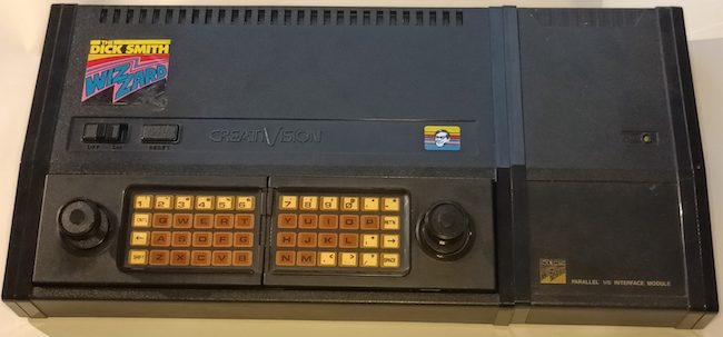
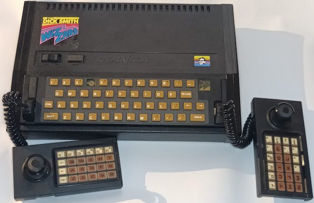
The keyboard on the CreatiVision is implemented by two large membrane matrices on the individual controllers. You can tell right away that it’s a lot denser than the “number pad” on the ColecoVision or Intellivision controllers, and it implements a full-ish 48-key keyboard plus two joysticks and four fire buttons.
By seating both controllers in the console, you can use it as a very unsatisfying keyboard.
Dick Smith (and probably VTech) also sold an aftermarket keyboard that was of generally higher tactility and was “permanently” installed, making it easier to write things that used both the keyboard and paddles.
Previous version
It’s been quite a while since I made any updates on this project, so it’s worth going over what was accomplished in the previous CreatiVision clone article back in 2023.
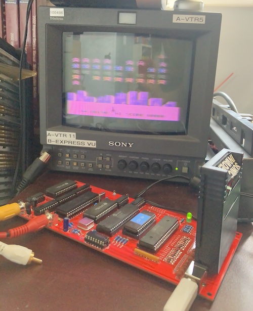
In that project, I used some old VTech schematics to build a single-board computer version of the CreatiVision. Because of the complexity of the keyboard, I decided to… not do it yet. As a result, I ended up with a working CreatiVision that I couldn’t actually play games on. You could only watch (and hear) the attract mode of Sonic Invader.
I called this clone DerivaVision, because it’s a derivative work and not creative at all!
In theory, my board was compatible with real CreatiVision controllers and keyboards, but I didn’t have any. The logical follow-up project would be to build an active converter which would adapt common interfaces, such as more readily-available game controllers and keyboards, to the CreatiVision’s parallel-matrix layout.
Version 1 of the adapter
Since I would need to poll the “new” devices and convert their signals to the CreatiVision’s expectations, I would need a microcontroller of some kind. At the time, I hadn’t worked with the Raspberry Pi Pico much, but I liked how fast it was, and I would need something fast to respond to the CreatiVision’s demands for joystick data in time.
Keyboards are read through the 6821 PIA on the CreatiVision’s motherboard. The specifics of interacting with them are all abstracted away by calls to the BIOS, which surely every well-behaved game will use with no exceptions.
Much like on the ColecoVision, the keyboard consists of multiple “select” lines. When they are asserted, the pins correspond to different signals. It’s essentially a keyboard matrix read, but with a very unconventional matrix.
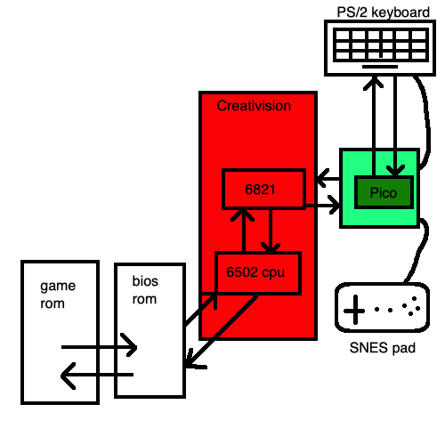
One thing I was worried about was interfacing the 3.3-volt Pico with a 5-volt system. For the sake of protecting the chip from its host machine, I chose a 74LVC245, which is an octal bus buffer that is capable of level translation.
Remarkably, using a 74LVC245 was cheaper than buying all the resistors and resistor networks to form a voltage divider. It even comes in DIP, which helps vibe with the rest of the system.
My plan after version one is complete is to integrate all of this into the main board of the DerivaVision. Maybe I can even get rid of the surprisingly expensive 6821 PIA in the process, along with the R-C snubbers that probably aren’t necessary when the CreatiVision CPU’s just talking to another microcontroller.
The sources
As you can see from the diagram above, I chose a PS/2 keyboard, and SNES controller. This is mostly because I already had the connectors on hand: feel free to mock me for my choices.
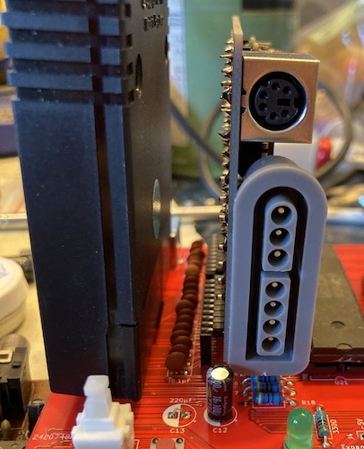
The biggest drawback of the SNES controller is the sheer size of the connector: it takes up a lot of board room, so much so that it’s not really practical to have 2 controllers plugged in. We can fix that later.
The biggest drawback of a PS/2 keyboard is that it is now becoming harder to find PS/2 keyboards in any random thrift store. Still, I just built a new (to me) Ryzen computer, and that fancy new motherboard had a PS/2 port. If it’s good enough for AMD…
The design
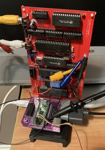
On the original CreatiVision, the controllers connect internally using a 0.1”-spacing pin header. I kept that pin header arrangement and tried to eyeball the positions, so that an original controller could still be used.
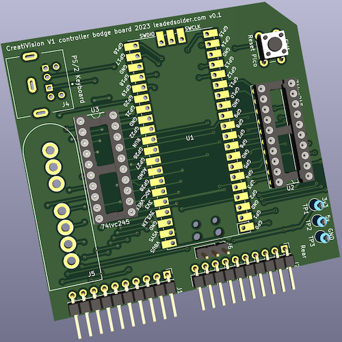
For my adapter, I ended up designing a vertical “card” that plugged into the pin sockets on the board using pin headers. This connector is cheap and easy to source, although it has a lot of drawbacks – it’s really easy to bend a pin, or insert the card one pin off, for instance.
Of course, the Pico needs power, and unfortunately the CreatiVision matrix connector doesn’t provide it (or ground.) To pick up +5V power and ground, I ended up re-using the logic-probe test hooks that were already present on the main board and running a soldered hook from the Pico card to the DerivaVision main board. To help prevent fraying from constant insertion and removal during testing, I globbed a bit of hot glue onto the wires to hold them still.
I’m mostly happy with this layout: it’s got very few parts, and the card is an interesting shape, which adds visual appeal.
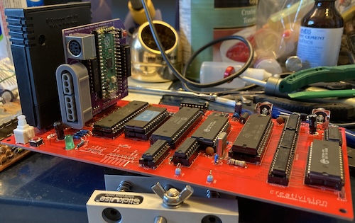
Hardware assembly
Once it arrived, I was able to assemble it using a right-angle pin header and two 10-pin “Arduino shield” stacking connectors from Amazon. A lot of annoying fiddling happened, and the board wobbles around a bit, but I think it looks pretty good for a prototype.
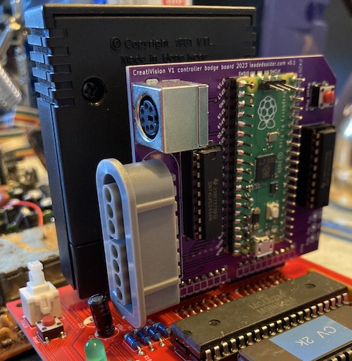
Please ignore all the mess on my desk, 2023 was one hell of a year. Honestly, it hasn’t gotten a lot easier since.
As you can see from this artsy shot, I got lucky and the SNES port just barely clears the capacitor here. Like my grandpa used to say, it’s better to be lucky than good.
It’s a lot of fun to pull this “card” in and out of the board, but I ended up leaving it installed into the DerivaVision, and using the debug pins on the Pico to flash it.
Firmware
The downside of making a microcontroller-based thing is that you have to write software for it. My day job is writing software, and although it’s not embedded software, I much prefer hitting things with a screwdriver or a hot chunk of metal to relax instead of chasing down linker errors.
Starting Out
I’d had a lot of hairballs before on previous Pico projects setting them up. Primarily, I had trouble making a CMake makefile that I was happy with. It seems like the official guidance for Pico projects is to either stick them all under a central root in your filesystem (so you can navigate upward to find the SDK,) or to write some very complicated makefiles.
When I was looking at polpo’s picogus code, I noticed that his CMake makefile had been automatically generated. After a quick search, I found the pico-project-generator repository managed by Raspberry Pi themselves. After installing tkinter1 (through the python-tk package in Homebrew) I was able to create a new project.
Overall, this process was fairly smooth, but I would have preferred that it set up .gitignore for the build directory. The default setup spews a bunch of object files and CMake caches all over the filesystem, which I definitely didn’t want to put into Git.
I had some trouble getting output from stdio to go to the USB port; it turns out that the CMakeFiles I had copied had turned off stdio-over-USB:
pico_enable_stdio_usb(creativision-gamepad-keyboard-v1 0)
Changing that to 1 made it appear in /dev/ and connection was easy:
% screen /dev/tty.usbmodem101 115200
Now I could see the results of my debug puts! That’s almost as good as having a real debugger.
SNES Controller
I had a lot of problems reading in the SNES shift register, which was very surprising as I’d pulled it off many times on other microcontrollers. Hitting “B,” the first button in the register, would set all the other buttons down, but not any of the other buttons.
One thing I forgot to do is actually tell the Pico which pins are outputs. After an hour of so of frustrated poking around, I grabbed the logic probe and discovered that the clock and latch pins were doing absolutely nothing. After some more frustrated poking around, I realized that I forgot to call gpio_init(...) on any of the output pins, which meant that they would just not produce an output when asked to do so.
void loop() {
    pad->update();

    SnesButtonState state = pad->get();

    if(state.buttons[SNES_B]) {
        puts("Button B is down");
    }
    if(state.buttons[SNES_A]) {
        puts("Button A is down");
    }
    // more buttons down here
With that solved, I was now able to read the SNES controller. I did consider implementing a “just-pressed” state, but the CreatiVision doesn’t have a facility to care about that, and will handle the unpressed -> pressed transition in software.
Getting the SNES pad to work was, in my mind, the “minimum viable” version of this project. Before I went too far down a rabbit hole adding PS/2 keyboard support, I wanted to check to see if I could actually output the joystick info all the way to the CreatiVision first.
Plus, I didn’t have any cartridges that used the keyboard…
Sticking Joy to the CreatiVision
This was a bit of a puzzle until I went for a drive and thought about it. Scouter3d from the CreatiVemu forums had posted a great thread about making an Atari 2600 joystick to CreatiVision adapter, and helpfully included the entire decoded matrix. The only problem was that I was confused by the explanation of how the matrix worked.
On the left controller Pin 1 to Pin 8 are connected to Pin 9 or/and Pin 10 when a key is pressed or the joystick moved…
On the left controller, pin 9 of the joystick connector is is PA3 on the 6821. I was initially not sure how to represent the state of “being connected,” but after my drive, it made more sense. Looking at the schematic for the CreatiVision clone, you can see that these lines are pulled up by 10kΩ resistors. If nothing is driving the lines they will forever be high, which the software calling the 6821 will understand as “not pressed.”
So, my theory was that the process went something like this:
- The software running on the CreatiVision asserts PA0..PA3 depending on what part of the keyboard matrix it wants to scan.
- The software checks to see which pins go low when this happens. These are the “pressed” keys. For example, if the CreatiVision is scanning PA3 (pin 9) at the moment, and it sees that pin 6 is also low, it interprets this as a “left joystick, moving right” action.
- The CreatiVision then proceeds to change the matrix by asserting a different combination of PA0..PA3 and repeats the previous steps.
If this was the case, then I needed some way to react really quickly (faster than the 6502 could read it back) to PA0..PA3 being changed, and to bring those pins on the matrix low as appropriate.
For my first draft, I didn’t do anything fancy. Speed was unlikely to be a problem, considering the Pico is a 132MHz future computer shrieking at a 2MHz 6502 through a 6821 peripheral interface.
Interrupts might disrupt the timing on my reading of the joystick or the PS/2 keyboard, and the Pico PIO accelerator, while a slick solution to this exact class of problem, seemed like a lot of extra hassle.
So I just wrote the simplest, dumbest code I could think of. I constantly check the “row select” pins and then remember which row the Creativision is trying to look at.
I store a 4 x 16-bit (unsigned short) “current keyboard matrix” array. Depending on which row I last saw the Creativision asking for, I send the corresponding entry of this array onto the 6821’s inputs using gpio_put_masked2. The pins that are pushed go low on this bitmask, and the CreatiVision looks at this and goes “hmm, yes, the left fire button is pressed.”
That way, I only need to remember which bit masks are set by a given key (in this case the SNES buttons) and then set those bit masks when I find out the button has been pushed or lifted.
My first run didn’t work: I had forgotten to hook the +5V and GND jumper wires to the board, so the Pico was not getting any power. After that was done, it still didn’t work.
How Do You Play Games, Anyway?
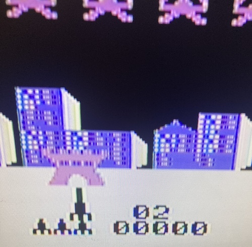
I went to find a manual for Sonic Invader, and realized I had to hit RESET on the system before I could get out of the attract mode and choose which game mode I wanted to play. Ah, old school games. In MAME, pushing the key “Z” started the game, but since I don’t have an overlay, that was momentarily beyond me as to what function that exactly was. That also didn’t work on my controller adapter, but at least now I knew I was in the right place in the game to accept input.
During this period, I was turning the system off, pulling the board out of the system, and flashing it with a USB cable. This was very frustrating, especially since I was debugging the matrix at the same time. Eventually, I realized I was too far ahead of myself, and I needed to build up a base of confidence. I had to go even smaller than emulating a single button!
To make sure I had everything right on the Creativision side, I made up a little test probe that consisted of two wires and a push button. With this, I would be able to emulate pressing a specific keyboard button, and also eliminate all of the complex functionality that was going on in my controller adapter. No sense worrying about my code and bringing out the logic analyzer if it turns out the junkyard 6821 I put in doesn’t work.
I knew from playing with MAME that all four fire buttons (each controller’s “left” and “right” triggers) would advance the “game mode” counter when the game was in the post-reset phase. All I had to do was get one of those four buttons to work. Easy, right?
After poking around with my homemade “button probe” while the system was running, I was able to isolate a pair of signals that sent a fire button: PA3 shorted to “pin 8” on my J1 header. This seemed to roughly correspond to “pin 3 + pin 2,” or “Fire Left (Right Joystick),” on the spreadsheet. It was at this point that I realized the spreadsheet had been counting from the other end of the connector for “pin 1” and would need to be inverted.
I should have built this little test probe in the first place; a lesson for next time.
After that, it was back to the Pico firmware, now that I knew what pair of signals I needed to send exactly. Turns out that I made a lot of really stupid errors with bit math in the firmware, and I had no end of trouble trying to get it to work at all. Turns out that – just like when I was trying to read the SNES joypad a few paragraphs ago – I once again forgot to do gpio_init before trying to feed any GPIO outputs, so nothing was ever coming out of the Pico.
Now that I knew the Pico was sending stuff, it was time to figure out why the system wasn’t receiving it. I put the Pico on the scope and found that… something was driving the Pico’s outputs, even when the Pico wasn’t?
As an aside, probing this thing is really annoying. I ended up laying the whole board on one lengthwise end, and let the cartridge hold the whole thing up like a bicycle kickstand. Precarious debugging? In my Leaded Solder post?
Get Off My Bus
After an evening of struggle trying to figure out why the Pico wasn’t talking to the CreatiVision, I looked at the schematic and had a terrible realization. Those 74LVC245 buffers which I had used for level translation between the 3.3V Pico and the 5V CreatiVision? Turns out I had the DIR pin backward.
When the DIR pin on the 74LVC245 is high, signals are buffered from the “A” side to the “B” side. I had the Pico on the “B” side, and the DIR pin was high, so the 74LVC245 was constantly trying to drive the Pico’s outputs while the Pico was also trying to drive them. Bus fight!! Not great for the Pico, but boy is that little chip tough. I slapped my forehead and quickly bodged it to work.
Remarkably, I actually thought ahead and left a jumper for the DIR signal on the board. Cutting that jumper and bodge-wiring DIR to ground was easy. Now, all of a sudden, it was driving the fire button super aggressively, all the time!
After cleaning up some more of my matrix math (and removing some debugging code I added in a sleep-deprived state) I was able to get the SNES pad to send a “fire button” signal all the way into the CreatiVision. The game mode advanced to “2.”
Success!
More Joy, Less Schtick
I was all ready to do some directional pad work, but first I had to make all four fire buttons work. For some reason, only the ones connected to PA0 and PA1 seemed to be reliably responsive.
Out of an abundance of paranoia, I set the code to flash the LED whenever it was scanning a certain row of the matrix. For PA0, the light was flashing very rapidly. For PA1, the light was flashing slightly less rapidly. By the time I got to PA2… it wasn’t flashing at all.
I began to suspect a timing problem. After putting it on the scope, I could see all four matrix pins were getting asserted at 60Hz. That’s a pretty tight window for the matrix scan. Eventually, I remembered that I had left a debug printf inside the “row changed” code… a debug printf that blocked the CPU while it was getting burped out onto the UART that I wasn’t even using!
Oops. After fixing that, all four fire buttons worked properly, although I was not sure whose fire buttons they really were.
At this point, I was also able to put together a “Z” button press, so I could start Sonic Invader. Unfortunately, the game wasn’t that enjoyable the first time. Things seemed laggy. Sometimes it would smear inputs into the next matrix, or feel like it was “dropping” my inputs, so I rewrote matrix scanning to use falling-edge GPIO interrupts instead of polling, and that seemed to make things better. Probably this is what I should have done in the first place, but sometimes you have to make bad decisions to get to a good place.
Directions were the next challenge, specifically diagonals. The CreatiVision actually has a very unusual (by modern standards) joystick – the membrane that it pushes underneath actually represents a 16-way joystick, whereas the SNES controller is only 8-way. Those of you who are better with math than I am will immediately recognize a problem.
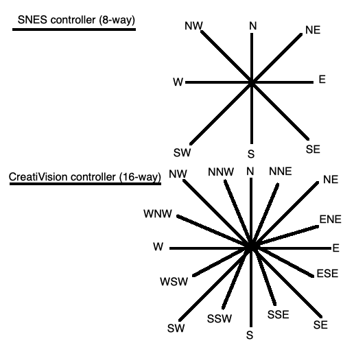
Because the CreatiVision controller is finer grained than the SNES pad, we can immediately see that we can only directly map to eight of those 16 directions. All of the 22.5-degree angles (e.g. NNW) are impossible to make with the SNES’s directional pad. As a result, this is not the most authentic controller adapter, and if any games are dependent on precision directional control, they won’t play as well on this adapter.
I decided that this was probably sufficient. If someone gets really upset about it, they can always make a version that uses a PlayStation analogue controller or some other analogue-stick-having thing.
Some more hacking-up of code got me to a point where the d-pad was working in at least the “left” and “right” directions. Sonic Invader didn’t give me much opportunity to test the others.
Now at long last, we have a working one-player controller adapter for the CreatiVision clone. That has one working fire button, one start button, and two directions. Not exactly the full suite of capabilities, but a lot more than “absolutely no way to input anything,” which is what we had before.
In order to get the keyboard working, though, and help nail down the last few oddities in my direction logic, I’d need to get or write some keyboard test software. With test software, I can make sure that the CreatiVision software is actually reading the key that I think I’m sending. That’s what we’ll do in the next article about the DerivaVision, which hopefully will take less than several years to arrive. Thanks for reading!
-
pico-project-generatorhas many command-line options and it seems to prefer that you use them. However, even if you don’t use the--guioption on launch, it will still crash becausetkinterisn’t installed. Since I had already used the bandwidth and disk space to install it, I decided to go the easy way out and use the GUI this time. Like all tools of this nature, it was annoying enough to get running that it didn’t save me any time. I probably won’t use this generator anymore now that I have a working project; I’ll just copy the repo contents and gut the source code. ↩ -
This is the same way that we write to the data bus on the v1 PC-6001 multi cart. ↩